-
PDF
Feuerhand_Beat_Lantern_Masterplan.pdf
Feuerhand Beat Lantern - Masterplan | Stand 14.09.20Seite 5 Netz Quelle Last / Zweck Leitung BAT_RAW P2160TC nach Pololu 5-V-Regler und Flash- AWG22-24 fuer Hochstrompfade Sicherung/Schalter Treiber 5V_SYS Pololu S13V30F5 XIAO 5V, SN74AHCT125 VCC, AWG24-26 NeoPixel V+ 3V3 XIAO 3V3 INMP441 VDD AWG28-30 GND gemeinsame
in „Auftragsarbeit gesucht: ESP32 / RGBW / Audio-Reactive Feuerhand-Umbau“ · Markt ·
-
Datei
fritzbox_7590_log.txt
tc=2 prio=1 signal=13 [ 0.509166][ T1] avm_yield_setup: YIELD_GPTC_ID : id=0x0005000b: cpu=0 tc=5 prio=3 signal=11 [ 0.519339][ T3] [0][yield_context_init] cpu=0 tc=2 mask=6000 tc_prio=1 [ 0.526486][ T29] [0][yield_context_init] cpu=0 tc=3 mask=1000 tc_prio=2 [ 0.533643][ T29] [0][yield_context_init] cpu=0 tc=4 mask=8000 tc_prio=3 [ 0.540751][ T29] [0][yield_context_init] cpu=0 tc=5 mask=0800 tc_prio=3 [ 0.547758][ T1] avm_yield_setup
in „FritzBox 7590 Boot Loop“ · Mikrocontroller und Digitale Elektronik ·
-
PDF
navico_3g.pdf
Mirrored: MC34717 Dual5A lit dimly Buck U19, U24 TC4427AE Gate Driver Cyclone 5E disabled U11 TPS54240 2.5A Buck U30 AR801 5 Q8,Q9 240 MHztransimpedanc e FDS6912A Amp 30V 6A N MOSFET 128 Mbyte 24MHz sine NAND EEPROM 5.0Vout U1 TPS54240 2.5A Buck lit i.MX6
in „Reparaturbericht: i.MX6 Resetschaltung in Navico Schiffsradar“ · Mikrocontroller und Digitale Elektronik ·
-
PDF
grundig_sonoclock_690.pdf
ADJUST FOR REMARK TP1,2 90MHz Speaker 90MHz L101 Max. o/p Vol. at max. position TP1,2 106MHz „ „ 106MHz TC102 „ „ „ „ 4) 75KHZ CRYSTAL OUTPUT ADJUST ADJUST FOR REMARK TP6,7 CHECK ONLY 75KHz± 10HZ 5) 1.8432MHZ CRYSTAL OUTPUT ADJUST ADJUST FOR REMARK TC201 TC201 1.8432MHz± 10HZ Note : 1. Use the digital meter
in „Radio Grundig sonoclock 690 - schaltet sich aus“ · Haus & Smart Home ·
-
PDF
signetics-1986.pdf
a non-saturating Schottky Number of inputs depends on the gate. clamped transistor technique. The 74SOO GENERAL TTL CIRCUIT family of TIL products are very high parlor, mance, high power devices. The most popu CHARACTERISTICS lar TIL category is the 74LS Low Power All TIL products are derived from a
in „7805 als Pegelwandler?“ · Analoge Elektronik und Schaltungstechnik ·
-
PDF
CSTC.pdf
, 4.19, 4.91, 5.00, 6.00, 8.00, 10.00MHz) *2 At -20 to +80D *3 For 10 years at room temperature *4 TC74HCU04 is used as the standard circuit for the MXJ040 series. *5 If connected with incorrect orientation, the above specification may not be guaranteed. *6 CSTCS series shall be recommended in automotive
in „Bauteilbestimmung Fluke 179“ · Analoge Elektronik und Schaltungstechnik ·
-
PDF
T-3.pdf
P0.7) 602-RP5000-412 4 72 SCREW(TTP CAP M3*8) 602-B600-056 7 73 SCREW (DIA.3*10,PTP) 602-M400-055 2 74 FOOT AND WASHER ASS'Y 701-DJ3000-3172 4 75 P/L OUT PUT PCB ASS'Y 704-3000A-4895 1 9 D.D Motor PCB Ass'y Part List REF NO. DESCRIPTION PART NO. Q'TY REMARK D.D. MOTOR PCB ASS' Y 704-3000-4862 1 CN101
in „Eprom von Denon DJ Laufwerk defekt Winbond 78e52“ · Mikrocontroller und Digitale Elektronik ·
-
PDF
RS-50-spec.pdf
EMISSION Compliance to EN55032 (CISPR32) Class B, EN61000-3-2,-3,GB9254 class B,GB17625.1, EAC TP TC 020 EMC IMMUNITY Compliance to EN61000-4-2,3,4,5,6,8,11; EN61000-6-2 (EN50082-2), heavy industry level, criteriaA, EAC TP TC 020 MTBF 228Khrs min. MIL-HDBK-217F (25℃) OTHERS DIMENSION 99*97*36mm (L*W
in „Willtek Schlumberger Stabilock 4031 4032“ · HF, Funk und Felder ·
-
 Bild
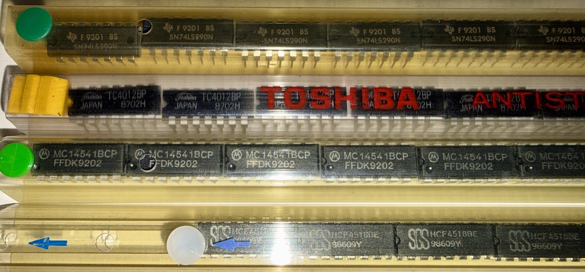
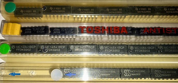
Reihe von integrierten Schaltkreisen in DIP-Gehäusen
F 9201 BS SN74LS290N, TC4012BP JAPAN 8702H, TOSHIBA, MC14541BCP FFDK9202, HCF4518BE 98609Y
in „[VS] Konvolut ICs, THT und SMD“ · Markt · · Fotos
-
 Bild
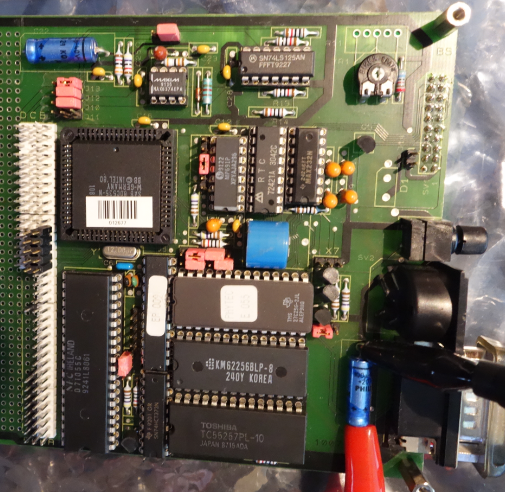
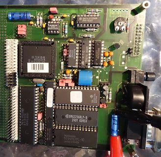
Bestückte Leiterplatte mit verschiedenen integrierten Schaltkreisen
SN74LS125AN, FFT9227, MAXIM, MAX857AEP, RTC, MAX252N, NXP, NXP/PHILIPS, 071051C, 9241L5061, KM62256BLP-8, 240Y KOREA, TOSHIBA, TC55257PL-10, JAPAN 8/15A
in „altes Phytec MCB-51 Monitor/Basic Befehle?“ · Mikrocontroller und Digitale Elektronik · · Platinenfotos
-
 Bild
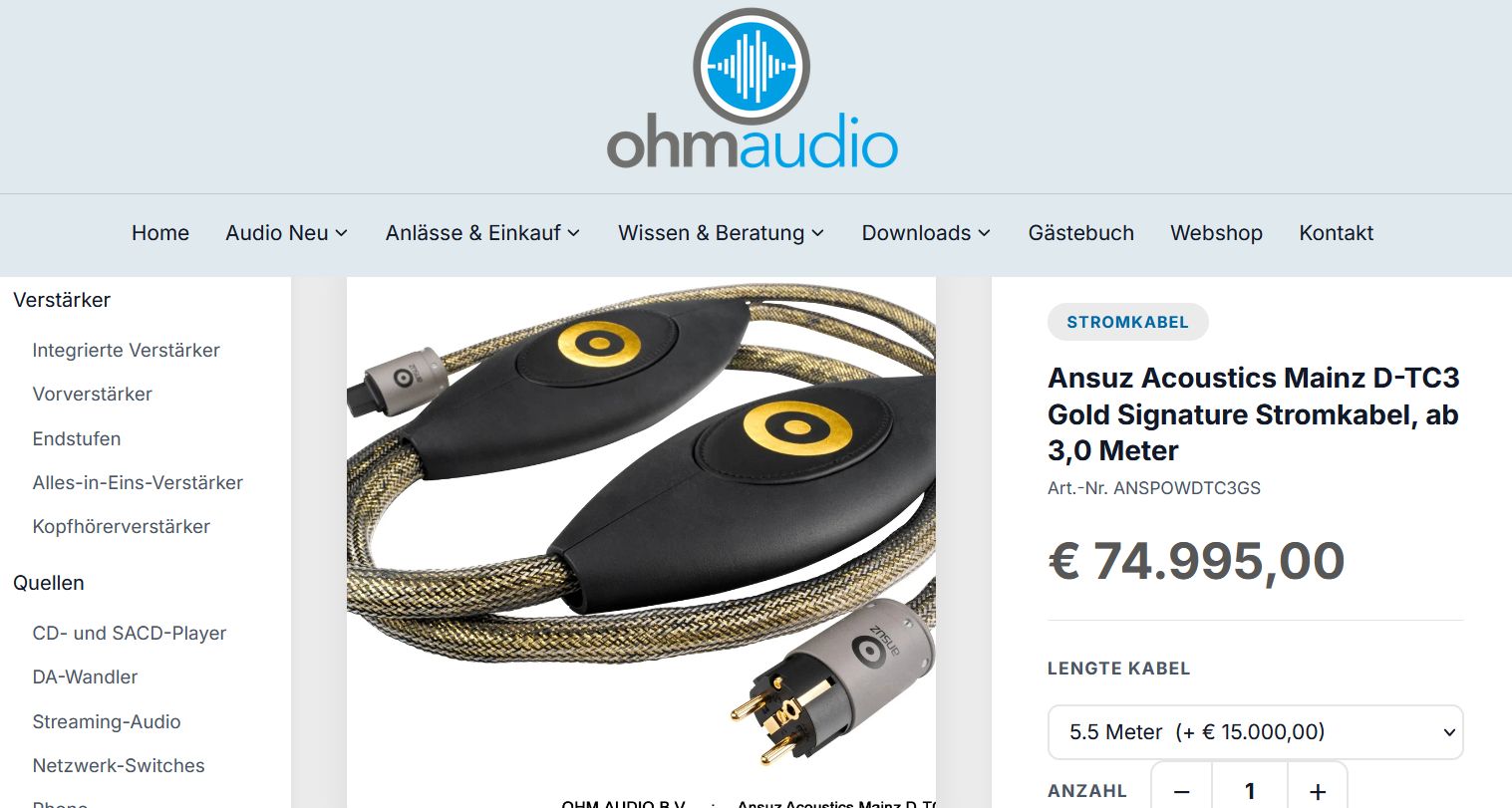
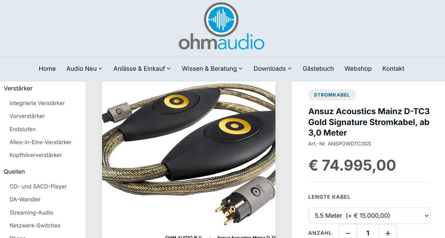
Webseite eines Onlineshops für Audiokabel
CD- und SACD-Player DA-Wandler Streaming-Audio Netzwerk-Switches Stromkabel Ansuz Acoustics Mainz D-TC3 Gold Signature Stromkabel, ab 3,0 Meter Art.-Nr. ANSPOWDTC3GS € 74.995,00 LENGTE KABEL 5.5 Meter (+ 15.000,00) ANZAHL
in „Identifikation Smd Elko“ · Analoge Elektronik und Schaltungstechnik · · Screenshots
-
 Bild
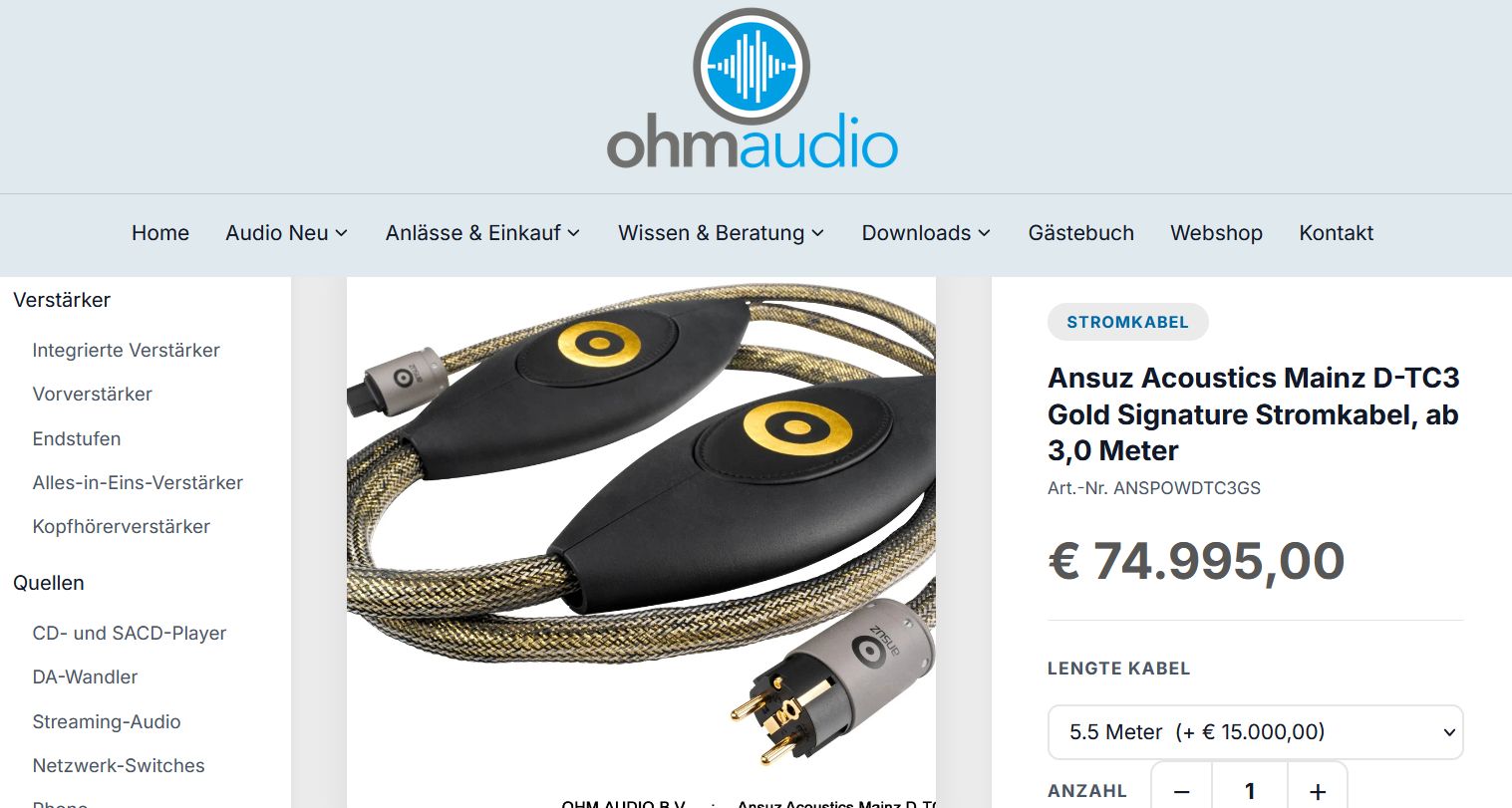
Webseite eines Anbietes für High-End Audio-Kabel
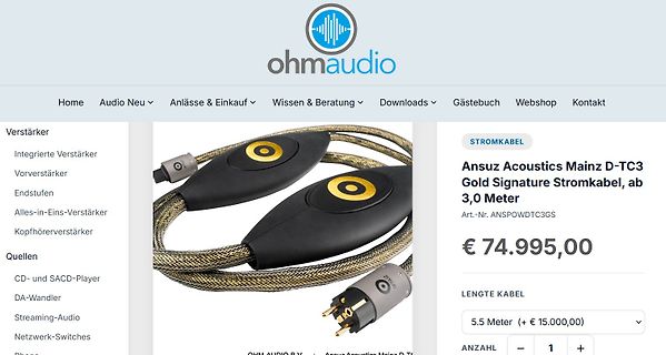
CD- und SACD-Player DA-Wandler Streaming-Audio Netzwerk-Switches Stromkabel Ansuz Acoustics Mainz D-TC3 Gold Signature Stromkabel, ab 3,0 Meter Art.-Nr. ANSPOWDTC3GS € 74.995,00 LENGTE KABEL 5.5 Meter (+ 15.000,00) ANZAHL
in „Identifikation Smd Elko“ · Analoge Elektronik und Schaltungstechnik · · Screenshots
-
 Bild
Webseite eines HiFi-Shops mit Stromkabel
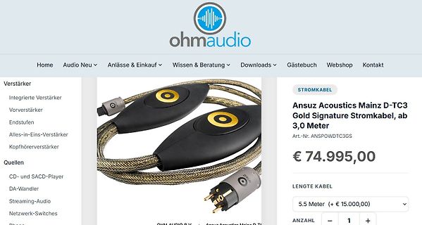
CD- und SACD-Player DA-Wandler Streaming-Audio Netzwerk-Switches Stromkabel Ansuz Acoustics Mainz D-TC3 Gold Signature Stromkabel, ab 3,0 Meter Art.-Nr. ANSPOW DTC3GS € 74.995,00 LENGTE KABEL 5.5 Meter (+ 15.000,00) ANZAHL
in „Ragebait: IsoTek V5 Sigmas - "Audiophiler" Netzfilter“ · Offtopic · · Screenshots
-
Datei
decode_rcf.py
RCoid Remote File", "Tastenfeld"} def extract_utf_strings(data): """Liefert (offset, text) aller Java-TC_STRING-Einträge (0x74 <len2> <bytes>).""" entries = [] pos = 0 n = len(data) while True: j = data.find(b"\x74", pos) if j < 0 or j + 3 > n: break ln = int.from_bytes(data[j + 1:j + 3], "big") s = data
in „Kann man eine Radio-Fernbedienung selber bauen ?“ · Analoge Elektronik und Schaltungstechnik ·
-
PDF
grip1.pdf
»Q ^a*%es*%t GRIP-1 Stückliste Bauteil Typ Funktion Bauteil Typ Funktion R8 68 Ohm Widerstand 216 74LS20 2xNAND, je 4 Eing. Z17 R7 150 Ohm 74LS27 3xNOR, je 3 Eing. R17 180 Ohm Z15 74LS32 4xOR, je 2 Eing. R1.R2.R6 270 Ohm Z35 74LS74 2xD-Flipflop R9 470 Ohm Bestimmt den BAS-Signalpegel Z12 74LS138 Dekoder 8 aus 3 R10-R12 470 Ohm Z13 74LS139 2xDekoder 4 aus 2 R3-R5.R14 Z34 74LS163 ' 2.2 kOhm Zahler 4 Bit R16.R18 2.2 kOhm (. Z36 74LS166 Schieberegister R13.R15 10 kOhm * s Z33 74LS173 Latch 4 Bit Z32 74LS244 Buffer Tristate TR1 2.2 kOhm
in „Conitec PROF-80 Informationsseite“ · Mikrocontroller und Digitale Elektronik ·
-
PDF
REN_icl7106-07-07s_DST_20251218.pdf
, units with a negative TC may cycle between overrange FIGURE 4B. and a non-overrange count as the die alternately heats and cools. All these problems are of course eliminated if an external FIGURE 4. USING AN EXTERNAL REFERENCE
in „Panel-Meter KAIFU FR-4“ · Mikrocontroller und Digitale Elektronik ·
-
PDF
rd70hvf1c.pdf
mobile radio sets. RoHS COMPLIANT RD70HVF1C-501 is a RoHS compliant products. ABSOLUTE MAXIMUM RATINGS (Tc=25 °C UNLESS OTHERWISE NOTED) SYMBOL PARAMETER CONDITIONS RATINGS UNIT V DSS Drain to source voltage Vgs=0V 30 V V GSS Gate to source voltage Vds=0V -5/+10 V Pch Channel dissipation Tc=25 °C 150 W Pin
in „HF Transistoren“ · Analoge Elektronik und Schaltungstechnik ·
-
PDF
Magazin_Bauteile.pdf
14-SOIC Texas Instruments Digikey 296-9173-5-ND 0,950 0,95 4 8 2 1 5 SN74HC595N Schieberegister 16 PDIP Texas Instruments Digikey 296-1600-5-ND 0,410 2,05 3 MC74HCT595ADR2G Schieberegister 16-SOIC ONSEMI Digikey MC74HCT595ADR2GOSCT-ND 0,410 1,23 2 5 SN74LS165AN Schieberegister 16 DIP Texas Instruments Digikey 296-14885-5-ND 0,920 4,60 3 CD74HCT165MT Schieberegister 16-SOIC Texas Instruments Digikey 296-CD74HCT165MTCT-ND 0,920 2,76 X 4 8 3 5 74HC04N Hex Inverter DIP14 NXP Segor 0,500 2,50 5 74HC126N Quad 3-St Bus Buffer DIP14 Texas Instruments
-
PDF
Y1112.pdf
TSM Peak gate current GRM 0.5 A Average gate power P 0.3 W G(av) Operating case temperature range TC -5 to +85 °C Storage temperature range T -10 to +110 °C stg Lead temperature during soldering 1.6 mm from the case for 10 seconds Tlead 230 °C electrical characteristics at 25°C case temperature (unless
in „Leuchtstoffröhren Starter für Effekt nutzen“ · Analoge Elektronik und Schaltungstechnik ·
-
PDF
Orion_Rev_3.0__1_.pdf
6K8 270E 6K8 100nF 100K 22E 1 2 2 R152 EXT CLK GND 51 74HC04 EXT CLK TERMINATION 22E C L33 U26 C 1 2 4 VDD OUT 3 OSC_10MHZ 2 1 MMZ2012R601A 1 GND CONT 10MHZ 3.2X5MM 1 C249 1 C217 +C203 1 C216 100NF 10NF 10UF 100NF 2 2 2 2 D35 Q9 SI2301CDS-T1-GE3 10MHZ_ENABLE
in „Suche Firma die für Privat BGA FPGA reballing macht“ · Markt ·
-
PDF
ADC0801_05.pdf
5 VDC and T MINT AT MAX unless otherwise specified. Symbol Parameter Conditions Min Typ Max Units TC Conversion Time CLK= 640 kHz (Note 6) 103 114 µs TC Conversion Time (Notes 5, 6) 66 73 1/CLK fCLK Clock Frequency VCC= 5V, (Note 5) 100 640 1460 kHz Clock Duty Cycle 40 60 % CR Conversion Rate in Free-Running
in „Verständnisfrage zum ADC080x (VIN-MIN/DC-Offset)“ · Analoge Elektronik und Schaltungstechnik ·
-
PDF
Stenorette_2010_SW.pdf
tissaious'sdFigur zun9.nisse ist ein sauberer Koplspiegel Vorausset- AIs w)eß9eräte uerden empfohlen: Tongenerator TC 40 . lvli-IlivoltmeterIvlV0 0szilLoskop z. B. G0 15 MSI Stromaufnahme Kontokt 6 Die Stromaufnahme beträgt bei ei.ngelegter Cassette am Bandanfang: \ bei Uiedergabe ohne 5igna1, max. 25 mA bei Aufnahme
in „Recht auf Reparatur“ · Offtopic ·
-
PDF
device.pdf
A NONE No Need WBPPGM V5.08 NATIONAL BPROM DM54S573/A/B NONE No Need WBPPGM V5.08 NATIONAL BPROM DM74LS471 NONE No Need WBPPGM V5.08 NATIONAL BPROM DM74S188 NONE No Need WBPPGM V5.08 NATIONAL BPROM DM74S287 NONE No Need WBPPGM V5.08 NATIONAL BPROM DM74S288 NONE No Need WBPPGM V5.08 NATIONAL BPROM DM74S387
-
PDF
infineon-bsb056n10nn3-g-datasheet-en.pdf
GSto 10 V Switching charge Q sw - 20 - nC VDD50 V, I D30 A, V =GSto 10 V Gate charge total Q g - 56 74 nC VDD50 V, I D30 A, V =GSto 10 V Gate plateau voltage Vplateau - 4.2 - V VDD50 V, I D30 A, V =GSto 10 V Output charge Q oss - 73 97 - VDD50 V, V =GSV 1) See ″Gate charge waveforms″ for parameter definition
in „Bauteilsuche Mosfet“ · Analoge Elektronik und Schaltungstechnik ·
-
PDF
Intersil_ICL8052_ICL8068_ICL71C03.pdf
(Continued) SUPPLY A TEST PARAMETER SYMBOL CONDITIONS MIN TYP MAX UNITS o Temperature Coefficient TC - 40 - ppm/ C Supply Voltage (V++ -V-) VSUPPLY ±10 - ±16 V Supply Current Total SUPPLY - 6 14 mA NOTES: o 8. The input bias currents are junction leakage currents which approximately double for every
-
PDF
pm2521ocr.pdf
UAT7I4HC 5322 209 86169 A 302 0 9 0 0 6 1 5322 209 8 5 8 8 5 A 401 090063 5322 209 89989 A 501 UA?741TC 4 8 2 2 2 0 9 8 0 6 1 7 A 502 WUA7I0HC 5322 209 8 6 4 1 4 7 A 601 UAT41TC 4822 209 80617 A 602 000064 5322 209 85887 A 603 oggc6o - 5322 209 85884 & 801 L M 7 8 L O 5 A C Z 5 3 2 2 209 8 0 9 0 3 A 802 UA741TC 4822 209 80617 D 1901 N74LS244N 5322 209 86017 D 1 9 0 2 S N 7 4 L S 1 6 1 A N 5 3 2 2 2 0 9 8 5 9 1 5 : D 1903 H E F 4 0 2 7 B P 5 3 2 2 209 1 4 0 5 5 D 1 9 0 4 P 8 0 3 5 5 3 2 2 2 0 9 8 6 4 7 9 : D
in „Pjilips PM2519“ · Markt ·
-
PDF
grundig32zollLedTV.pdf
74 52 D903 T 71 57 L803 T 17 71 R209 B 82 61 R625 T 43 27 C314 B 127 49 C702 T 168 20 C838 T 29 72 C1000 T 101 31 L804 T 74 73 R210 B 99 73 R626 T 49 21 D904 T 65 106 C315 B 131 58 C703 T 175 24 C839 T
in „Reparaturbericht LED-TV Grundig 32 VLE 5620 BN Ton gut, aber kein Bild“ · Analoge Elektronik und Schaltungstechnik ·
-
PDF
pm2534ocr.pdf
Input unit eee eee eee e e e e e e h h 6-3 6.2.4 Interchanging input unit .......eeeeeeeecereeeeecee O74 6.2.5 Fuses Pe eeeeee ee 6-4 6.3 Trouble shooting e e e e 6-5 7. SAFETY INSPECTION AND TESTS AFTER REPAIR AND MAINTENANCE IN THE PRIMARY CIRCUIT 7-1 7.1 General directives 2.2.02 ceecsccceccesecceseseseens
in „Pjilips PM2519“ · Markt ·
-
PDF
PCF7922ATT.pdf
...................................................................................................74 21.1 Avoid leakage current in POWER-OFF mode ...................................................................................................................74 21.2 LED output configuration.......
-
PDF
SAB80C517A.PDF
ident corrected 65 – Description of t corrected LLIV 65 – Program Memory Read Cycle: t PXAV added 74 – Oscillator circuit drawings: MQFP-100-2 pin numbers added. Page Subjects (changes since last revision 01.94) – Minor changes on several pages 47 – Table 6 corrected Semiconductor Group 2 1994-05-01
in „[V] 3 St. Vintage 8051er - Infineon SAB-C517A-4RM- MQFP100 (10€)“ · Markt ·
-
PDF
AN1543-D.PDF
B MTP8N50E 0.98 (with MC33262based PFC) Of course, the sicannot be zero, but it is small enough to TC= 40°C (steady state, in free air) make this new technology a good choice to design an electronic lamp ballast. The time delays built with R3/Ciss , R4/Ciss and Q1 Q2 Also, the ON voltage is very close
in „Reparatur EVG für T5 Röhre“ · Analoge Elektronik und Schaltungstechnik ·
-
PDF
53131a_53132a_bedienungsanleitung_deutsch_komprimiert.pdf
sal Count r e Gate & ExtArm j ≡ M M MEASURE » ⅛ ⅛ ⅛ z l irι ,3 GATE:TIME RUN j⅞jjkJg 4tW ≡ RUN jGΛT⅛TC> j-⅜ ⅛ ..H... START: fS ii≡ iΠ H i ≡* ¾ a ⅛ ⅝ ι⅛ r⅛ ⅞ﮏa⅝⅛⅛π⅛M s ∞ STOP: s ≈ ----------<__------', w ⅜wΓ" 'jooi------ ¾ B ≡ rτS ∣Gλ⅛r'0⁄G⁄TS'''⅝j ExtArm ?: IOf ⅜ ≡ HP 5315 31A/132A/132A Universa Count
in „[V] HP/Agilent 53131a/53132a Bedienungsanleitung deutsch“ · Markt ·
-
PDF
l9805e.pdf
5.6 Controller area network (CAN) . . . . . . . . . . . . . . . . . . . . . . . . . . . . . . . . . 74 5.6.1 Introduction . . . . . . . . . . . . . . . . . . . . . . . . . . . . . . . . . . . . . . . . . . . . . . 74 5.6.2 Main features . . . . . . . . . . . . . . . . . . . . . . . . . . . . . . . . .
in „ST L9805-E Motortreiber mit H Brücke und ST7UD05 Kern“ · Mikrocontroller und Digitale Elektronik ·
-
PDF
siplace-s27hm.pdf
This measurement should be 74.2 mm for the S-27 HM TIP Move one PCB into the placement area and clamp the PCB in place. Now measure the distance between the top edge of the lifting table (rubber stop) and the bottom edge of the PCB. This height should be exactly 94 mm for the HS-60 and 74 mm for the S-27 HM. NOTE The actuator underthe clampingsensormust bemounted0.2 -0.3 mm lowerto guarantee reliable actuation of the clamping sensor. Æ Push one PCB manually through the entire PCB conveyor
in „Siplace 80 Potentialverteiler“ · Mikrocontroller und Digitale Elektronik ·
-
PDF
PMT_handbook_v4E.pdf
500 1000 1500 2000 I Q E SUPPLY VOLTAGE (V) THBV4_0445EA Figure 4-45: Example of EADCI THBV4_0445EA 74 CHAPTER 4 CHARACTERISTICS OF PHOTOMULTIPLIER TUBES b) AC expression In low-level-light measurements, the DC components of dark current can be subtracted. The lower limit of light detection is determined
in „Suche nach geeignetem OpAmp als Impedanzwandler“ · Analoge Elektronik und Schaltungstechnik ·