-
 Bild
Bild
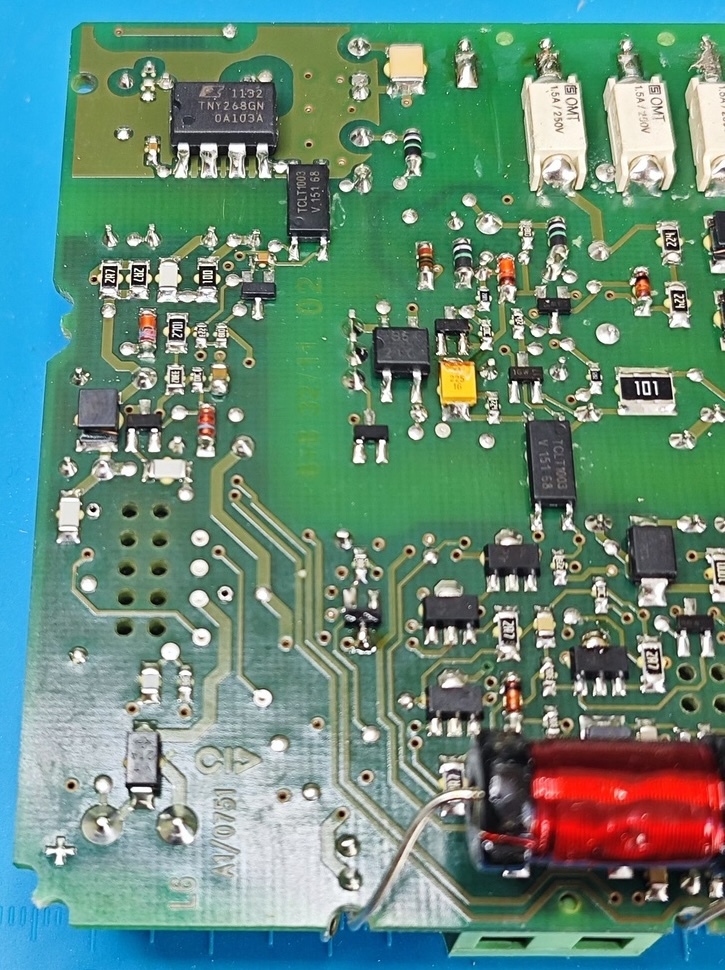
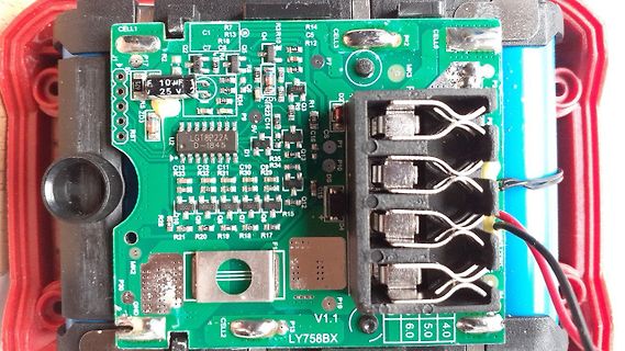
Nahaufnahme einer Leiterplatte mit elektronischen Bauteilen
TNY268GN OA103A 0.5A/250V TCLT003 V 151 68 101 L6 A1/0751
-
 Bild
Bild
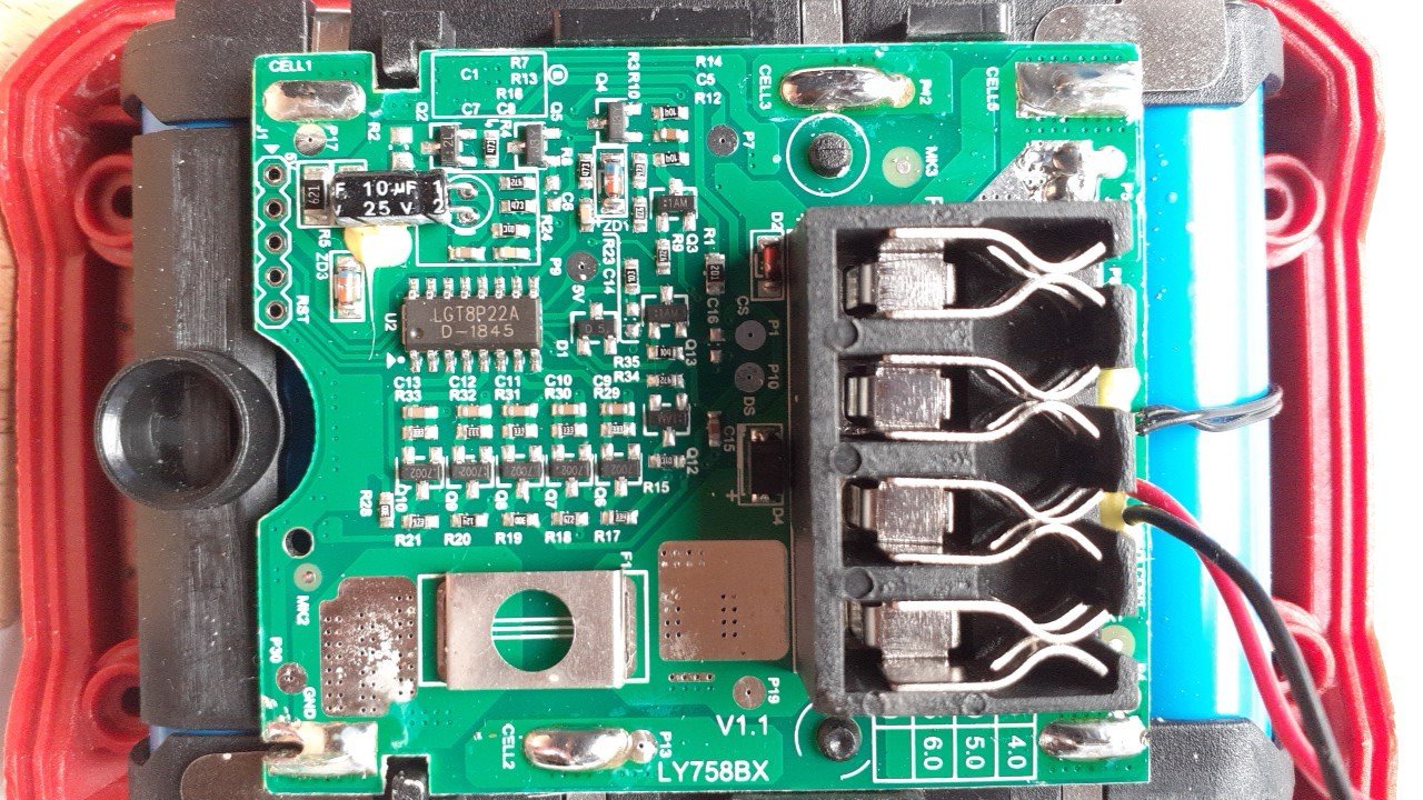
Foto einer Leiterplatte mit Bauteilen und Steckern
R13 R14 R15 R16 R17 R18 R19 R20 R21 R22 R23 R24 R25 R26 R27 R28 R29 R30 R31 R32 R33 R34 R35 LGT8P22A D-184.5 10uF 25V P8 P9 P10 P11 P12 P13 P14 P15 P16 P17 P18 P19 P20 P21 P22 P23 P24 P25 P26 P27 P28 P29 P30 P31 P32 P33 P34 P35 P36 P37 P38 P39 P40 P41 P42 P43 P44 P45 P46 P47 P48 P49 P50 P51 P52 P53
-
Thread
Suche Software / Firmware für Quadra Chek 200
Konfigurationsdaten werden einfach der Reihe nach an die entsprechende Speicheradresse geschrieben. Der FPGA ist u.a. für die Auswertung der Tasten zuständig.
Ein Hitachi SP14Q002-A1 ist als Display verbaut. Grüße
-
 Bild
Bild
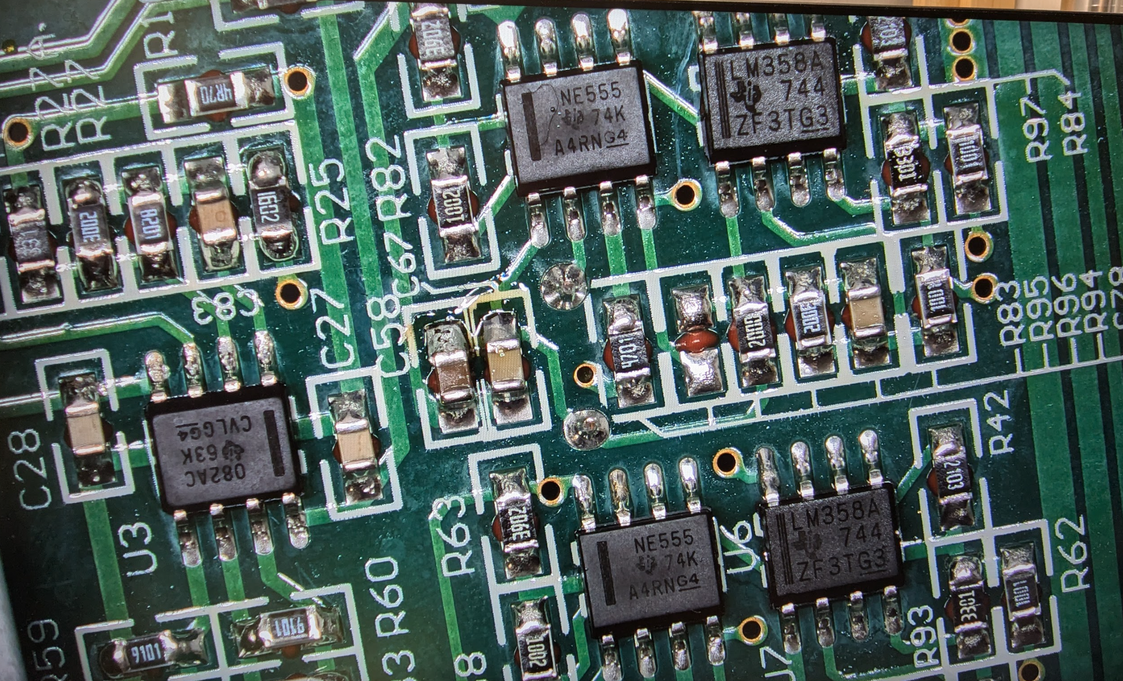
Nahaufnahme einer bestückten Leiterplatte
NE555 74K A4RNG4, LM358A 744 ZF3TG3, C27, R25, R82, C58, C83, C28, U3, CVLG94 63K 082AC, R63, R60, R62, R93, R97, R84, R95, R94, R96, R83, R42, 101, 201, 202, 102, 103, 104, 105, 106

-
Thread
Hilfe benötigt! Pi Compute Module 4 Carrier Board ohne Funktion!
einen Vorwiderstand. Soll das durch den GPIO limitiert werden oder was? Ob der CTR da ausreicht? 50mA LED Strom würde dann 50mA durch den Schalter jagen. Ob das genug ist? Muss man halt im Relay Datensheet überprüfen. Sonst frage ich mich ob da genügend Kondis verbaut worden sind? Ich denke mal,
: USB_OTG_ID Input (3.3V signal) USB OTG Pin. Internally pulled up. When grounded the CM4 becomes a USB host but the correct OS driver also needs to be used. --> Pin 101 USB_OTG_ID ist nicht beschaltet
-
 Bild
Bild
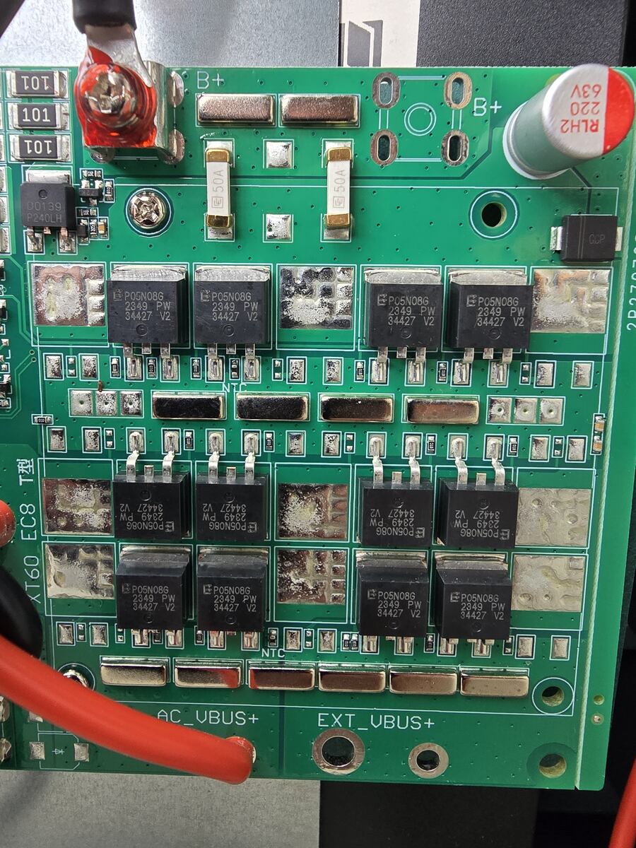
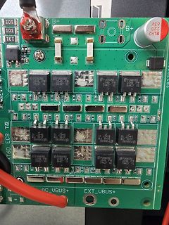
Leiterplatte eines Batteriemanagementsystems oder Ladegeräts
101 B+ 63V 220 RLH2 50A P24DLH P05N086 2349 PW 34427 V2 AT60 EC8 AC_UBUS+ EXT_UBUS+
-
Thread
Hugging Face-Roboter, Ubuntu für DragonWing, neue Methode zur Behebung von Fehlern in PCBs
Bedürfnisse des NVIDIA-Embedded-Ökosystems ausgerichtet ist. ### HuggingFace Standard Open SO-100 & SO-101 - vergleichsweise preiswerter Roboterarm. Arduino experimentierte zum Höhepunkt des Arduino-Bürgerkriegs mit einem als Braccio bezeichneten Robotergriff - da die entwickelnde Seite im Arduino-Bürgerkrieg
news/lower-prices-for-4gb-and-8gb-compute-module-4/ eine Preissenkung an: [c] From now, if you buy a standard operating temperature Compute Module 4 from a Raspberry Pi Approved Reseller, it will cost you $5 less for a 4GB RAM variant, and $10 less for an 8GB RAM variant. [/c] Bei Betrachtung
-
 Bild
Bild
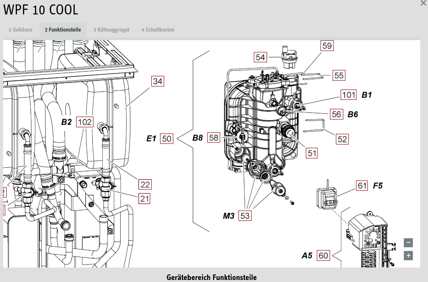
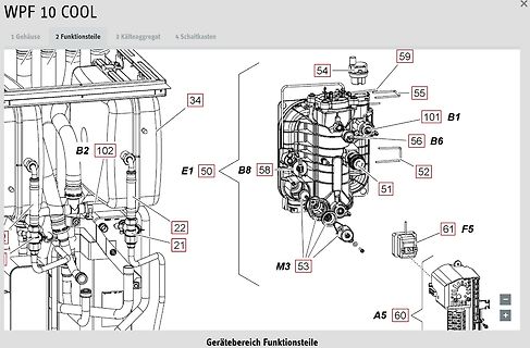
Explosionszeichnung oder technische Zeichnung von Funktionsbauteilen
WPF 10 COOL 1 Gehäuse 2 Funktionsteile 3 Kälteaggregat 4 Schaltkasten B2 102 E1 50 B8 58 54 59 55 101 B1 56 B6 52 51 22 21 53 M3 61 F5 60 A5 Gerätebereich Funktionsteile
-
Thread
LED-Streifen fiepen bei PWM <=100%
wie es bei angelegten 12V per Schalter nichts fiept. Beim gedimmten Kreis 1 ist ein Schaudt LIS101 verbaut. Hier fiept nichts. Schließe ich den Dalcnet Dimmer an den Kreis 1 an, fiept es auch hier. Offensichtliche Lösung: Schaudt LIS101 für Kreis 2 kaufen. Aber gibt es eine einfache Möglichkeit
/info/p34575_Schaudt-Dimmermodul-LIS-101--12V.html P.S. Schaudt heißt scheinbar nun Lippert
-
Thread
Was verändert sich bei falscher Impedanz einer Elektretmikrofonkapsel
Jürgen schrieb im Beitrag #7870011: > Der Strom durch die Kapsel beträgt 0.17 mA bis 0.29 mA, je nach > Multimeter. Du hättest den Kurzschlussstrom messen sollen!
Jürgen schrieb im Beitrag #7870011: > Der Strom durch die Kapsel beträgt 0.17 mA bis 0.29 mA, je nach > Multimeter. > Das Elavi16 misst den höchsten Strom, das Uni-T UT70D den niedrigsten. > Ich vermute mal, das Uni-T hat einen höheren Innenwiderstand auf der mA > Strecke.
-
 Bild
Bild
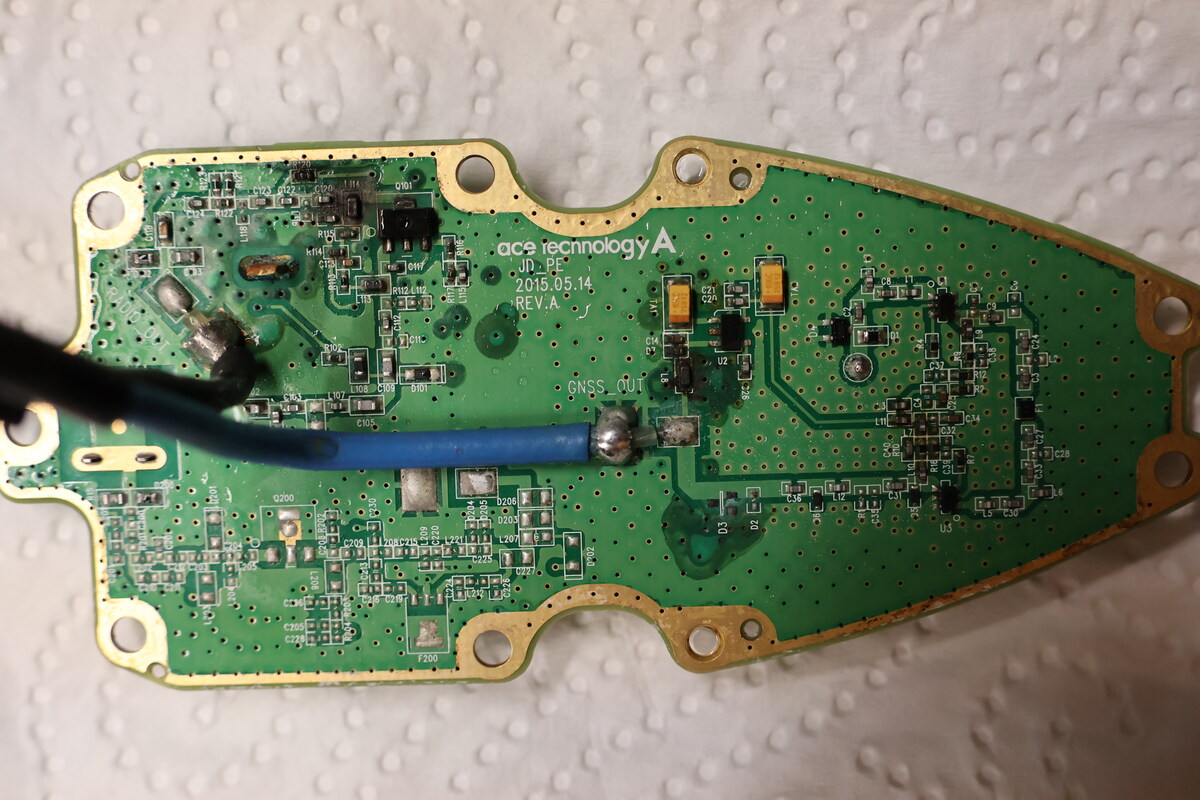
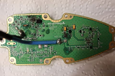
Foto einer Leiterplatte mit Kabelanschluss
ace technology A JD_PF 2015.05.14 REV.A GNSS_OUT C101 C102 C103 C104 C105 C106 C107 C108 C109 C110 C111 C112 C113 C114 C115 C116 C117 C118 C119 C120 C121 C122 C123 C124 C125 C126 C127 C128 C129 C130 C131 C132 C133 C134
-
Thread
Leistungsfaktor aus den beiden Modulen ZMCT103C und ZMPT101B errechnen?
Ist es möglich aus diesen beiden Modulen ZMCT103C und ZMPT101B zusammen den Leistungsfaktor zu errechnen?
Ist das so schwer, Links zu posten? https://nous.technology/product/nous-smart-wi-fi-socket-a1.html https://nous.technology/product/pdf?slug=a1t&alias=de anscheinend ein polnisches Produkt aus Warschau Steht da irgendwo, dass die beiden Trafos eingebaut seien, oder vergleichbare Sensoren
-
 Bild
Bild
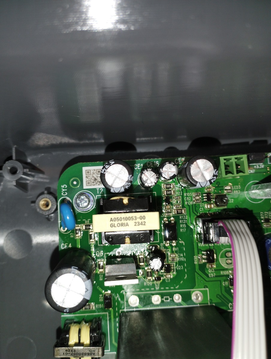
Nahaufnahme einer Leiterplatte mit elektronischen Bauteilen
CY5 CE1 CE16 LED3 CN7 +3.3V A05010053-00 GLORIA 2342 R132 R131 R15 R17 R110 R109 R108 R107 R106 R105 R104 R103 R102 R101 R100 R98 R97 R96 R95 R94 R93 R92 R91 R90 R89 R88 R87 R86 R85 R84 R83 R82 R81 R80 R79 R78 R77 R76 R75 R74 R73
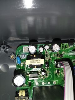
-
 Bild
Bild
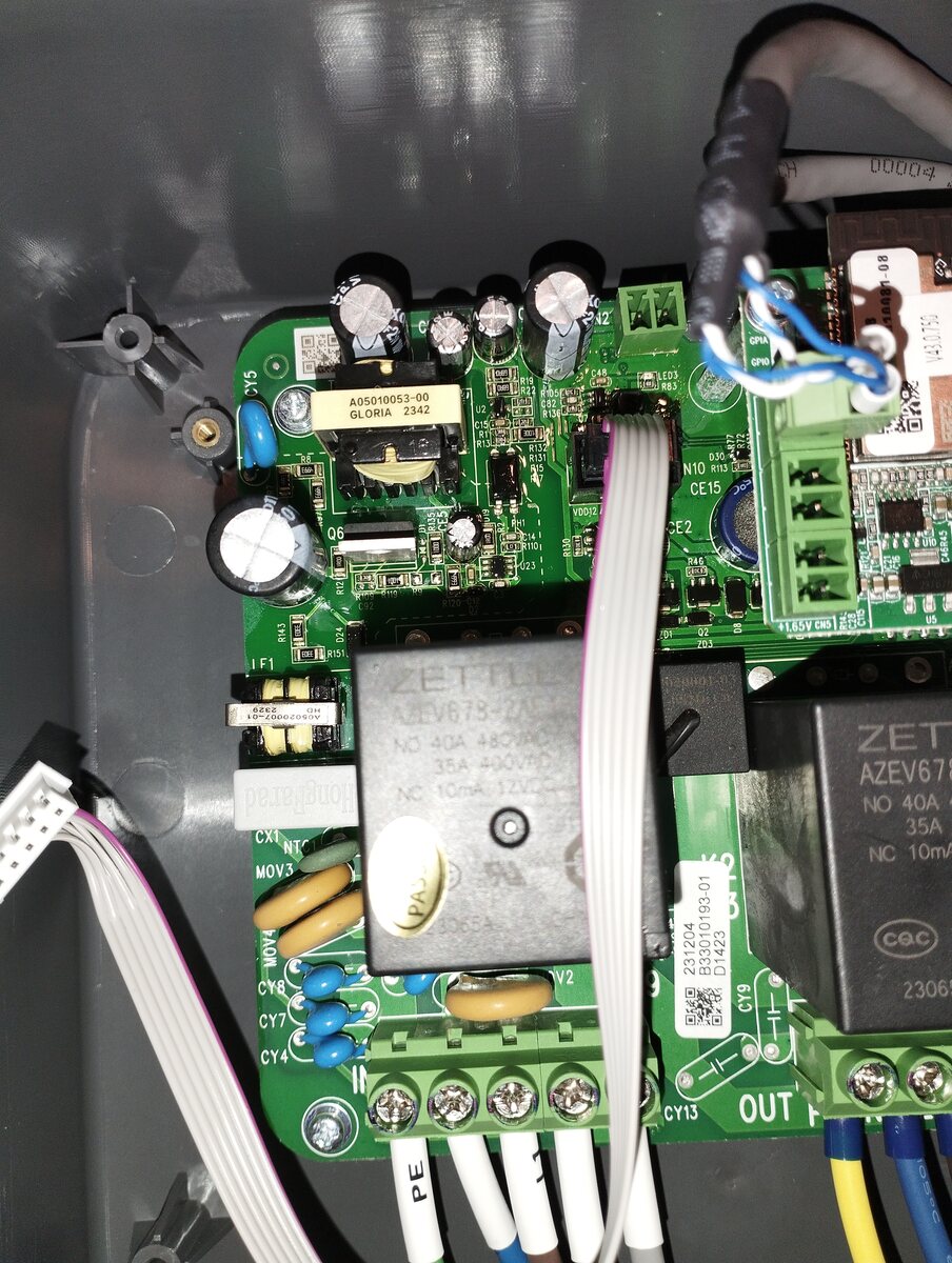
Foto einer bestückten Leiterplatte mit Relais und Kabeln
A05010053-00 GLORIA 2342 CY5 C42 LED1 LED2 LED3 D55 R13 N10 CE15 R13 R14 R15 R16 R17 R18 R19 R20 R21 R22 R23 R24 R25 R26 R27 R28 R29 R30 R31 R32 R33 R34 R35 R36 R37 R38 R39 R40 R41 R42 R43 R44 R45 R46
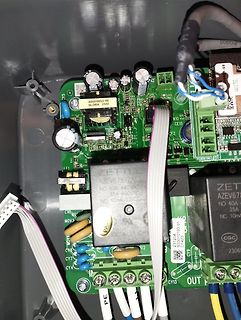
-
Thread
Treppenlicht Ausschaltvorwarnung LED Strombegrenzer etc.
Gesetz berechnet werden: 𝐼 = 𝑉 gesamt 𝑅 gesamt = 230 Volt 2.645 Ω ≈ 0.087 A I= R gesamt V gesamt = 2.645Ω 230Volt ≈0.087A Der Strom, der durch die Reihenschaltung fließt, beträgt also 0,087 Ampere. Berechnung der Leistung: Die Leistung
elektrische Leistung berechnet: 𝑃 gesamt = 𝑉 gesamt × 𝐼 = 230 Volt × 0 , 087 A ≈ 20 Watt P gesamt =V gesamt ×I=230Volt×0,087A≈20Watt Ergebnis: Die beiden 40-Watt-Glühlampen verbrauchen in einer Reihenschaltung an 230 Volt insgesamt ungefähr 20 Watt. Jede
-
Thread
Grüne Farbe sehr schwach in Panasonic Fernseher. Nachstellbar?
Ein Oszi hätte ich, aber "All waveforms have been taken using a standard colour bar pattern." kann ich nicht erfüllen.
umfangreichen Application Note (Application information for I2C-bus controlled TV-processor TDA933XH- AN98073, 101 Seiten) in der u.a. auch die TDA61xx berücksichtigt werde (siehe z.B. BASIC APPLICATION OF THE CCC-LOOP WITH THE TDA61XX).
-
Thread
Sollwertvorgabe: DAC oder PWM über RC-Glied besser?
> gut passenden DAC gefunden. Brauchen würde ich 10 Bit und 0V(GND)..5V > Ausgangsspannung DAC101C081CIMK/NOPB: I2C mit 4 Adressen im SOT-23-6 für 1.50. Und mit ziemlich kräftigem Rail-to-Rail Ausgang, PWM braucht hinter dem Filter einen OP.
geringe Spannungen Sinn ergeben, weiß ich im Moment noch nicht. Kann sein, daß die angestrebten 15A Eingangsstrom dabei nur bei unpraktikabel engem Tastverhältnis erreicht werden und dann funktioniert das nicht. Das ist das gleiche Problem, was der China-Lader meines Kumpels gerade hat. Wenn das von
-
 Bild
Bild
Leiterplatte mit elektronischen Bauteilen
Infineon Q226D, R112, R103, R121, R118, R102, R115, A 3120, 0015/93, V113, T201, HYB201, T201, V213, C214, C116, V138, L101, 1.0A/168UH, C48, PC1, V235, C219, V43
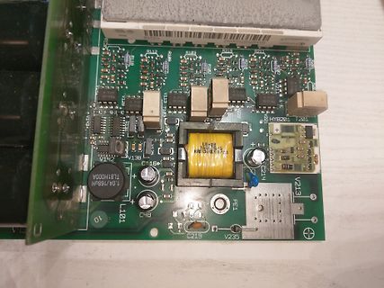
-
 Bild
Bild
Nahaufnahme einer Leiterplatte mit Bauteilen und Markierungen
Q1 D ND1X R2 C1 ELH +5V 0V R1 10J C6 50J R150 R150 F91 101 50J 36A
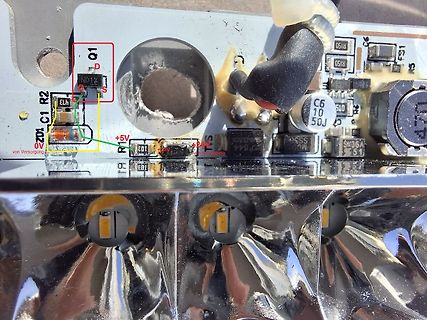
-
 Bild
Bild
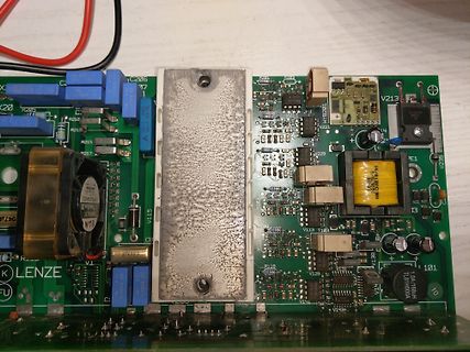
Leiterplatte eines Netzteils mit Lenze-Beschriftung
V217, V115, CB, LENZE, C2, R202, R203, V213, V21, V29, PE1, V235, T103, V113, V128, V14, V15, V16, 10A, TL81H000A, 101
-
Thread
BMS 4s Anschließen
Es muesste so ein Board sein: https://www.electronics.com.bd/battery-charger/lipo-18650-4s-20a-li-ion-battery-charger-protection-board-hx-4s-d20
. schrieb im Beitrag #7861890: > Bei dem oberen roten BMS was ich auch erwecken konnte werden die 101 > gekennzeichneten R's warm auch ohne Last. Die R gehen zu den B1,2,3 > Abzweig des Akku. Tja, vielleicht ist das ja auch nur ein BMS für LiFePO-Akkus ...
-
 Bild
Bild
Foto einer bestückten Leiterplatte in einem Gehäuse
ZQ-C01A-009, 470, 100, 100, 100, 220, 101, 470, 100, 100
-
 Bild
Bild
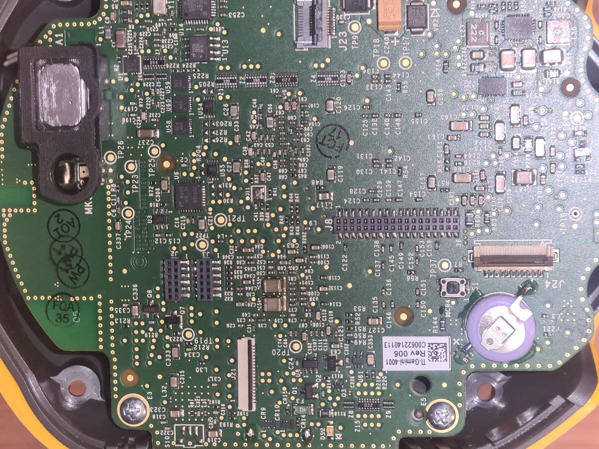
Nahaufnahme einer Leiterplatte mit Bauteilbeschriftungen
A1, U13, C253, J23, TP9, R2, R1, R23, C249, C250, C251, C252, U2, R25, C197, C196, C195, C194, C193, C192, C191, C190, C189, C188, C187, C186, C185, C184, C183, C182, C181, C180, C179, C178, C177, C176
-
Thread
Suche preiswerten Lötkolben
Zum Thema TS101, dazu habe ich zwei gefunden. - MINIWARE Smart Soldering Iron TS101 - TS101PTS200 Ich nehme an, der empfohlene Lötkolben ist der Miniware? Wobei den gibt es in unterschiedlichen Ausführungen. TS101-BC2/-B2/-I???
-
 Bild
Bild
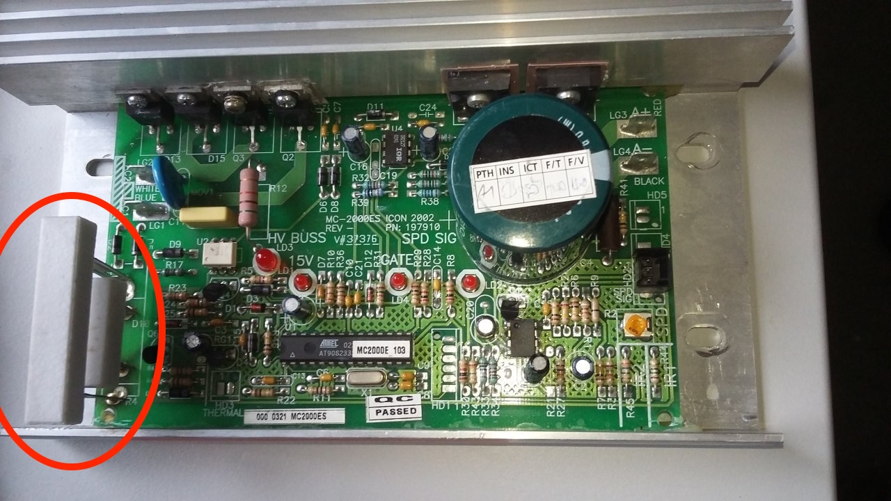
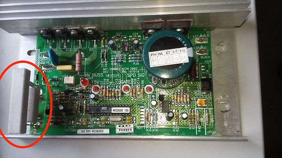
Foto einer Leiterplatte mit elektronischen Bauteilen
LG3 RED WHITE BLUE LG4A BLACK HD5 HD1 LG1 LG2 LG3 D15 D3 Q2 C24 U4 C16 R3 C19 R38 R4 R12 MC-2000ES ICON 2002 PN: 197910 HV BUSS V#239E SPD SIG LD3 15V R5 R6 R7 R8 R9 R10 R11 R12 R13 R14 R15 R16 R17 R18 R19 R20 R21 R22 R23 R24
-
Thread
Kennt jemand eine Transistorzündung
modernen Transistor? https://www.reichelt.de/de/de/shop/produkt/darlington-transistor_npn_400v_15a_135w_to-247-375063
modernen Transistor? > https://www.reichelt.de/de/de/shop/produkt/darlington-transistor_npn_400v_15a_135w_to-247-375063 Modern wäre ein IGBT.
-
 Bild
Bild
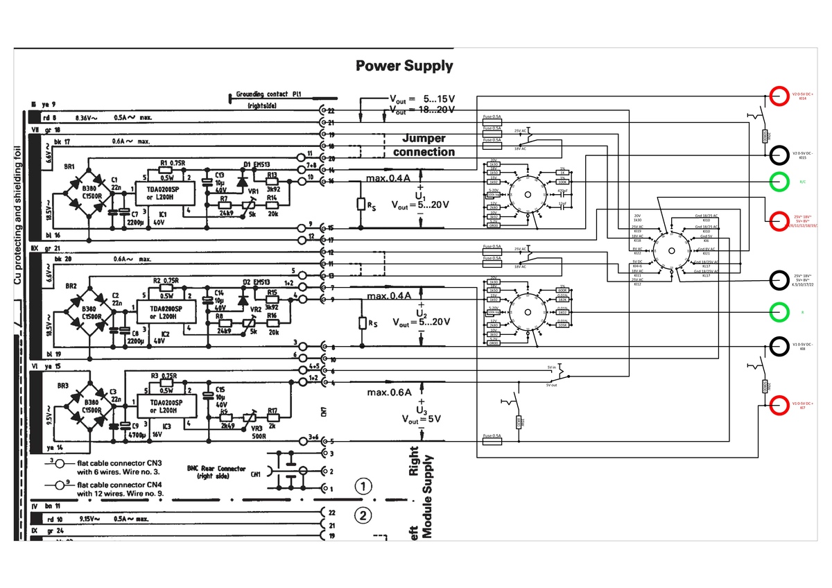
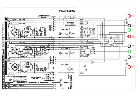
Schaltplan eines mehrstufigen Netzteils
Power Supply Grounding contact Pt1 right/left B ya 9 0.8V~ max. 0.5A~ max. VR 17 0.6A~ max. Cu protecting and shielding foil 18.5V~ BR1 C1000 C1 TD4020SP or L200H K1 bl 16 BX gr 21 0.6A~ max. BR2 C1000 C2 TD4020SP or L200H K2 bl 19 18.5V~ 19 20 21 22 23 24 25 26 27 28
-
Thread
analog Signal 5v ausgeben mit 3v3 µC
deiner Ausgabe von 2001 nicht enthalten. Du brauchst die Ausgabe von 2002: https://web.mit.edu/6.101/www/reference/op_amps_everyone.pdf Das für dich wichtige Kapitel gibt es auch noch mal als gesonderte Version: https://www.ti.com/lit/an/sloa030a/sloa030a.pdf rhf
ist da eine Ausnahme: https://www.ti.com/document-viewer/lit/html/SLOA277B#GUID-EFCC8464-CF16-4EA1-A67C-C24D4BE8C9ED/TITLE-SLOA277ID-D03898E6-395A-414B-FBF6-94D8E9B10C28
-
Thread
neuere BluePill (WeAct) I2C1 will nicht
Schachtel oder ähnliches, stell die neben Deine Platine und leg' Dein Smartphone da drauf, dann ist es a) vernünftig ausgerichtet und b) es verwackelt nicht, weil Du es nicht in der Hand hältst. Und sieh Dir das Bild vor dem Hochladen wenigstens selbst mal an.
durchforstende Errata-Dokument ist dieses: https://www.st.com/resource/en/errata_sheet/es0340-stm32f101xcde-stm32f103xcde-device-errata-stmicroelectronics.pdf ?
-
Thread
Elektronikladen in Ingolstadt in den 80ern
1898. D-1-61-000-121 Datum 19. Juli 2012 https://de.wikipedia.org/wiki/Liste_der_Baudenkm%C3%A4ler_in_Ingolstadt Bis 2010? war da der Raumausstatter Hans Redler (Tapezier- und Dekorationsgeschäft) aktiv.
Kraftfahrt-Bundesamtes bearbeitete Städte: Regensburg, Fürth, Ingolstadt, Landshut, Weiden, Straubing, Rosenheim u.a. (siehe Anzeige im PDF Seite 318->342)