Min SEG pad pitch 47um Min COM pad pitch 40um Bump height Nominal 12um Bump size Pad 1, 106, 124, 256 80um x 50um Pad 2-18, 89-105, 107-123, 257-273 25um x 80um S Pad 19-88 40um x 89um Pad 125-255 31um x 59um S Pad 274-281 (TR pads) 30um x 50um D marknment Position Size + shape (-2973, 0) 75um x 75um
Beispiel eines low cost DC Wattmeters / Leistungsmesser. ATmega8 und 4HSG21010B26-1W. 7...20V max 10A => max 200 Watt. Ohne Potentiometer, die Justierung erfolgt in der Assembler-Software .equ FAKTOR_U=291 .equ FAKTOR_i=263 Menuegeführt: Leistung, Strom, Spannung, ADC Spannung, ADC Strom
= 2 ⋅ N ⋅ (1 + OCRnA)------------------- The N variable represents the prescaler factor (1, 8, 64, 256, or 1024). As for the Normal mode of operation, the TOVn Flag is set in the same timer clock cycle that the counter counts from MAX to 0x0000. 15.8.3 Fast PWM Mode The fast Pulse Width Modulation or
FREQ_148 * sqrt(A_SQ / accel))/100; // Find out after how many steps does the speed hit the max speed limit. // max_s_lim = speed^2 / (2*alpha*accel) max_s_lim = (long)speed*speed/(long)(((long)A_x20000*accel)/100); [/c] Woher kommt z.B. das /100 im step_delay? Sind das Anpassungen
Festpunktberechnungen und -skalierungen, dann wenigstens im Binärsystem mit Faktoren wie 64 oder 128 oder 256, eben "2 hoch irgendwas".
Max M. schrieb im Beitrag #7608882: > Leider wird aber erst noch an einem Schnelltest gearbeitet Vielleicht dann bald beim TÜV, dann ist nach 5 Jahren Feierabend, da eine von 500 Zellen leicht defekt
Gerhard O. schrieb im Beitrag #7610784: > So wie hier? Hahaha! Hat jetzt 256 PS und 435Nm.
Danke an Max und Bergler für die guten konstruktiven Hinweise, im Gegensatz zu anderen hier....
Compilers musst Du Dir dann jedenfalls keine Gedanken mehr machen, das ist alles in CBOR definiert. In 256 Bytes lässt sich mit CBOR so Einiges unterbringen. Gruß, Oliver
deutlich andere Werte: ACS712: max. 13mA Quelle: file:///Users/A287500/Downloads/ACS712-Datasheet.pdf ... dort auf S. 5 PeDa-Oszillator: unter 1mA (ja, mehr ist es nicht!) Arduino Uno: max. 686 mA (natürlich
executable. as well as 4-byte patch entry instructions that overwrite the ROM. Modern Broadcom chips have 256 Patchram slots [46]. The format is very similar to the one defined within WICED Studio Legacy chips are connected via UART, and there is no other 6.2 .hdf files [20]. The configuration data section
und > die Eingänge vertragen maximal zusammen 50µA Woher hast du die 50µA? Waren es nicht eher max 50mA? https://forums.raspberrypi.com/viewtopic.php?t=300735 Leider ist nicht ganz klar, ob die 50mA jetzt für source und sink gelten. Auch könnten es die absolute max. Rating sein. Auf S. 619
datasheet.pdf steht folgendes (also eher die 50mA nicht ausreizen): Maximum Total IOVDD current IIOVDD_MAX 50 mA Sum of all current being sourced by GPIO and QSPI pins Maximum Total VSS current due to IO (IOVSS) IIOVSS_MAX 50 mA Sum of all current being sunk into GPIO and QSPI pins
details of the physical dimensions are: • The 12 tick marks are placed on a circle of radius r*(200/256). • Each tick is a point of radius r*(10/256) • The seconds hand has length r*(200/256) and width r*(3/256) • The minutes hand has length r*(150/256) and width r*(9/256) • The hours hand has length
Feature Pb Free Solder Process Non-Pb Free Solder Process Average Ramp Up Rate (T to T ) 3°C / second Max. 3°C / Second Max. s p Preheat - Temperature Min (T sin.) 100°C 150°C - Temperature Max (T sax.) 150°C 200°C - Time (tsMin to s Max) 60 to 120 seconds 60 to 120 seconds Time Maintained Above Critical
das Teil. Es gibt einige Digitalpotis die 24V abkönnen: AD5291/92/93/AD7376 (30V SPI Analog), MAX5436-39 (30V SPI Maxim), MCP41HVx1 (36V 256steps SPI Microchip, Reichelt)
Michael B. schrieb im Beitrag #7598594: > 256steps kollidiert aber mit Ersi schrieb im Beitrag #7598562: > 0,1V schrtte das kann dann nur 24V /256 = 0.094V Schritte und die auch nur mit fester Schrittweite.
external N-channel MOSFETs to drive a bipolar stepper motor or two brushed DC motors. A – Built-In 1/256-Step microstepping indexer microstepping indexer is integrated, which is capable – Drives external N-Channel MOSFETs of step modes from full step to 1/256-step. – Optional STEP/DIR pins An ultra-smooth
color 0,0 pattern at Mode 15. several minor adjustment may be required. 2) Set External Bright to MAX position and Contrast to Adjustment should be following procedure and after MAX Position. warming up for a minimum of 10 minutes. 3) Select PRESET START → BIAS CAL command and Enter. • Alignment appliances
select-field-programmable-gate-array-fpga-and-complex-programmable-logic-device-cpld-product-families-pcn-117954-01-product-discontinuance-end-of-life-reason-for-revision-removed-max-ii-max-ii-g-max-ii-z-from-the-list-of-impacted-products-and.html MAX II is removed from the list of impacted products after considering customer feedback and current supply uncertainty in the broader
Christoph db1uq K. schrieb im Beitrag #7592471: > > aber: > MAX II products will be reviewed for EOL in 2024 > also nur aufgeschoben Was älteres als MAX 10 sollte man von Intel nicht nehmen!
CCW fähig sein Ich habe dazu diese Bauteile gefunden die passen könnten: Motor - 283856 - EC-max 22 Ø22 mm, bürstenlos, 25 Watt, mit Hall-Sensoren https://www.maxongroup.de/medias/sys_master/root/8839853244446/DE-239.pdf Sensor - 499357 - Encoder ENC 16 EASY, 256 Imp. https://www.maxongroup.de
BLDCs. Wobei, Vorsicht, was ist ein BLDC? Das ist ein "Bürstenloser Gleichstrom-Motor". Der EC max ist _kein_ BLDC, er kann nicht (bzw. nur mit einem externen Controller) mit DC betrieben werden. Ohne Controller ist er eher ein Schrittmotor. Der Controller sagt nur nach jedem ausgeführten Schritt
--------- G = D(169) H = D(170) K = D(171) L = D(172) Gosub Hconv 'Hex to Dez W = W / 1000 W = W * 256 '* 0.0000256 W = W / 10000 A1 = W Print ; " A1 " ; A1 ; " KWh (Bezug)" 'positive (used) G = D(197) H = D(198) K = D(199) L = D(200) Gosub Hconv W = W / 1000 W = W * 256 W = W / 10000 A2 = W Print ;
***************************************************** ; Analoger Eingang RA0, Spannungsmessung bis max. 5,00 V ; Segmente an RD1 bis 7, Dezimalpkt. Dig2: RD0, Katoden an RC4,5,6 ; Taster an RA4, aktiv low ;******************************************************************** List p=16f884 #include <p16f884
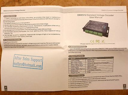
9. Important reminder
Power Source Selection
2. Specifications
24CH Decoder
Input voltage DC5V-24V
Max load current
Max output power 360W@12V/360W(12V)/1720W(24V)
Output Scale level 256 levels
Input signal DMX512/1990
Output DMX Channel 24Ch PWM
Dimension L145xW98xH30(mm)
Weight 500g
3. Basic Features
Easy Module V1.0 6.1.2 Electrical characteristics of PINs PIN PIN Nr Voltage Current Description (max) RX 11 USART 1 - To RS232, RS485 or TX 12 RS422 device driver USER 14 TTL 2 25 mA User sets logic state RES 15 TTL - Hardware reset if logic low EN 16 TTL - Low will disable the reader device LEDr 17
ATI RADEON X1300 PCIe Bus Type PCI Express (x16 lanes) Graphics Card Maximum Vertical Refresh 85 Hz (256 MB) Rate Display Support Integrated 400 MHz RAMDAC Display Max Resolution 2048 x 1536 Board Display Options DVI-I + TV DVI-I supports analog CRT or flat panel or digital flat panel (using DVI-A, DVI-D
ATI RADEON X1300 PCIe Bus Type PCI Express (x16 lanes) Graphics Card Maximum Vertical Refresh 85 Hz (256 MB) Rate Display Support Integrated 400 MHz RAMDAC Display Max Resolution 2048 x 1536 Board Display Options DVI-I + TV DVI-I supports analog CRT or flat panel or digital flat panel (using DVI-A, DVI-D
Methods for returning structure, class and union objects (except intrinsic vectors __m64, __m128, __m256, __m512) segment word size 16 bit 32 bit 64 bit compiler M o W M o W M G M W M L i r l t r l t c u c n c u s n o s n o O e O o , f d m f d m S c S s S t t p D t , max number of integer registe0s 2 2
umskalieren auf echte Messwerte. Meine Schätzung für den Prozessor wäre: Mindestens 128KB RAM, eher 256KB Und mindestens 256KB FLASH, eher 1MB Bei CAN würde ich mir die Option auf FD CAN nicht verbauen (bei Neuentwicklung), daher würde ein Prozessor dieser Reihe empfehlen: STM32G4 STM32H7 Damit
müsste man > wohl alle noch umskalieren auf echte Messwerte. Die Messwerte müssten als Hex-Werte (max. FF FF) multipliziert und in float gewandelt werden. Anschließend wird daraus vermutlich ein Mittelwert und Fehlerwert (z.B. RMSE) gebildet.
grôßeren Netzen. Ich kann bei > 32 Informationen später auch auf 29 Bit (2.0B) erweitern,weiß ich. @Max Schön, daß du auch was konstruktives beigetragen hast...
Ich plane jetzt, diese Informationen ins erste Datenfeld packen. Damit könnte ich dann schon gleich 256 Informationen kodieren.
Der Programmablauf ist also so: 1. 256 Samples einlesen 2. FFT darauf machen und Ergebnis speichern 3. 256 Samples einlesen 4. FFT darauf machen und Ergebnis speichern 5. 256 Samples einlesen 6. FFT darauf machen und Ergebnis speichern 7. 256 Samples einlesen 8. FFT darauf machen und Ergebnis speichern 9. 256 Samples einlesen 10. FFT darauf machen und Ergebnis speichern 11. Mittelwert bilden 12. Mittelwert ausgeben 13. weiter bei 1
. Additional error: +(0.25 % of fuL1-scaLe value + 0.03 %/K) rI External voltage: max. Urr" = L25 V but not exceedin8 U, = 180 V General t- ıigital display: 20-digit fluorescent dispLay (green) 5 x 7 dot matrix, character size 9 x 6.3 m Single-value display: 4 to 5 digits, max. 0 30000 with sign, unit and channel assignment Two-value display: 4 digits, max. 0 9999 ııith sign, unit and channel assignment, measured vaLues freely selectabLe for display Three-value display: 4 digits, max. 0 ... 9999, display of Irrs, Ur* and P (ııith sign) and channel assignment
Max I. schrieb im Beitrag #7582270: > das wird alles irgendwann voll. Kann man ja vielleicht nochmal > gebrauchen ;) Bei mir wird inzwischen lieber neubestellt statt lange gesucht :)
arbeitet, dann versuche VirtualBox mit Windows, KVM und Seamless Mode. Wenn das nicht geht, dann 256er SSD rein und Windows drauf. Keine Zeit auf halbgare Bastellösungen verschwenden. *kann natürlich abweichen, die Vorraussetzungen sind nicht bekannt
V D U C U T V C M M C C C A A R C S O S S P E E / A A A A A O O O 0 K C H A Program/Data JTAG EMU 256 RAM D1 256K Bytes Data 64 32 McASP0 R/W 16 Serializes Program/Data C67x+CPU 32 256 ROM Page1 D2 256K Bytes Memory Data 64 Controller 32 R/W Program/Data u McASP1 B 256 ROM Page2 32 6 Serializes Program 256K Bytes A M I/O INT Fetch D Program/Data P 32 McASP2 S 256 ROM Page3 c 2 Serializes 5 256K Bytes M 32 DIT Only 2 Program CSP 32 32 32 SPI1 Cache 256 u B 32K Bytes PMP DMP n i 32 SPI0 t 32 32 r g f 32
gefälschten Marken, getoppt nur noch von wenigen - z.B. Shimano-Ketten; legendär war das Angebot einer 256GB-"SanDisk"-SD-Karte, während SanDisk selbst nur max. 200GB herstellen konnte; Andreas S. schrieb im Beitrag #7580896: > Ähnlich ist es auch bei sehr vielen anderen Marken, > die für ehemals sehr
PROTRUSION. 16 1 8 8 PL. 5. MAXIMUM MOLD PROTRUSION 0.15 (0.006) PER SIDE. 1 MILLIMETERS INCHES G DIM. MIN. MAX. MIN. MAX. R X 45° A 9.80 10.00 0.386 0.393 C B 3.80 4.00 0.150 0.157 J C 1.35 1.75 0.054 0.068 –T– D 0.35 0.49 0.014 0.019 SEATING F 0.40 1.25 0.016 0.049 D 16 PL. K PLANE M F G 1.27 BSC 0.060 BSC
Max M. schrieb im Beitrag #7579016: > Wenn deine Kiste so verseucht ist, dass der Virus deine Passwörter > verbigen konnte, dann hilft sowiso nur noch plattmachen/neueaufsetzen! Das sehe ich auch so
#7581768: > Was ist von solchen Produkten wie von Sandisk zu halten, die mit "high > endurance" oder "max endurance" werben? Ich würde Abstand halten. Wenn die Firma „gute“ und „nicht so gute“ anbietet, ist das geplante Fehleranfälligkeit.

 Bild
Bild