Offset Error vs Temperature Across Input Ranges 80 1 ------ CH0, -----,C----- CH2 0.75 ----- CH3,--- CH4, ------ CH5 ------ CH6,----- CH7 60 0.5 e ) v m 0.25 e r f o r40 E 0 e e m f-0.25 u O N20 -0.5 -0.75 0 -1 0 0.2 0.4 0.6 0.8 1 1.2 1.4 1.6 1.8 2 2.2 2.4 2.6 2.8 3 ±40 ±7 26 59 92 125 o Offset Drift (ppm
GRUB to systemd-boot should do so by removing the GRUB packages and installing systemd-boot at the same time: # apt install systemd-boot grub-efi-amd64-signed- E: Removing essential system-critical packages is not permitted. This might break the system.[/pre] Das kommt mir vor wie "I'm sorry,
shim-signed shim-signed-common shim-unsigned The following NEW packages will be installed: libip4tc2 libsystemd-shared systemd-boot systemd-boot-efi 0 upgraded, 4 newly installed, 14 to remove and 0 not upgraded. Need to get 1923 kB of archives. After this operation, 955 MB disk space will be
Stefan M. schrieb im Beitrag #8048000: > dann verfällt eventuelles > Restguthaben. Sam schrieb im Beitrag #8048543: > Dass ist genau dass Problem wenn es dann mal einen Anbieter gibt > verfällt das Guthaben nach 4 Wochen Junge... Aktualisiert mal eure Vorurteile. Seit *2006* (Urteil
: Selbst die Telekom hat sowas: > https://iot.telekom.com/tgkp-resource/blob/84974/aec6acef366732e6310eb44558671be4/iot-embedded-connect-data.pdf > ... das gleiche Modul kann man auch in Form eines Eval-Kits "nRF9151-DK" > kaufen, welches dann einen vorinstallierten Tarif von Onomondo hat. >
this topic? • Started to work ~6 months ago at Corellium, virtualizing iPhones (amazing stuff!) • W e have lots of work to focus on,no time to do any research (hopefully again in the near future) • No completed research on iOS currently • I just bought that E-Scooter ,and said "why not?!" TheTarget TheT
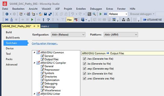
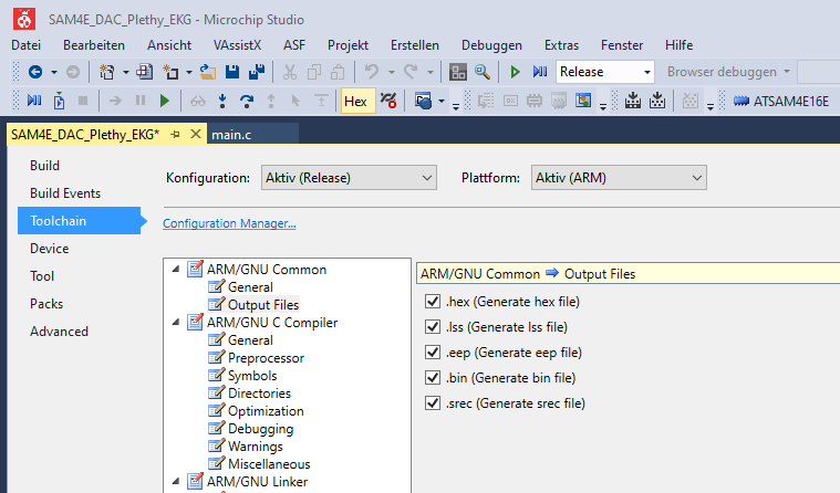
Microchip Studio 7 verwendest könntest du Assembler, bare C oder Arduino-style C++ verwenden für AVR und SAM uC. Assembler scheinst du nicht zu verstehen. Da übliche uC nicht genug Anschlüsse haben um z.B. 6 7-Segment Anzeigen statisch anzusteuern und du keine Schieberegister als Porterweiterung nutzen
Plexiglas steht die immer auf VOLL. Immerhin sind die LM5624-11 doppelt so hell wie eine DDR VQE23E . Klar, passiert dir nicht, wenn du superhelle Displays kaufst sind die blendend hell auch ohne Strom. Nur hast du noch nie irgendwas gekauft oder gebaut wir man an deinen fehlenden Bastelbildern
Hier ist der Beweis, falls du es selber nicht glaubst: https://de.m.wikipedia.org/wiki/Koryph%C3%A4e
27.5=55MBit/sec. Da ist dann noch ein Viterbifehlerschutz drauf, das ist dann bei dem Transponder 3/4 - d.h. fuer 3 Bits kommt jeweils ein 4. Bit zum Fehlerschutz dazu. Das rueckwaerts gerechnet: 55 * 3 / 4 = 41.25MBit/sec nach Viterbi. Dann ist noch ein RS-Code drauf, bei dem werden an jedes 188
Dimensional drawing Weight b s Nominal diameter V Weight RMS mm V g 5 11 … 460 0.3 … 0.7 . h 7 11 … 460 0.4 … 1.1 a 1) m 10 11 … 680 1.0 … 3.0 3 14 11 … 1000 1.4 … 7.6 Bottomview 20 11 … 1000 2.7 … 15.7 a e The weight of varistors in between these voltage classes can be interpolated. ød a e 1) SeatingplanetoIEC60717
DIMENSIONS (inch dimensions are derived from the original mm dimensions) UNIT A A1 A 2 A3 bp c D(1) E(2) e H E L Lp Q v w y Z(1) max. mm 1.75 0.25 1.45 0.25 0.49 0.25 5.0 4.0 1.27 6.2 1.05 1.0 0.7 0.25 0.25 0.1 0.7 0.10 1.25 0.36 0.19 4.8 3.8 5.8 0.4 0.6 0.3 8o 0.010 0.057 0.019 0.0100 0.20 0.16 0.244
entnehmen. tor betriebsbereit. Zur Kontrolle leuchtet die grüne Betriebs-LED unter dem Netzschalter. 4 TOELLNER Electronic Instrumente GmbH Bedienfehler Standardwerte TOE 7704 bis TOE 7711A E. 10 PLL-Frequenzübernahme aus freilaufendem Betriebsart: freilaufender Generator für Geräte ohne Betrieb nur für
Temperature (Noninverting) (Inverting) 65 10 10 ) A VS= ±5V 8 10mV VS= ±15V 8 (60 AV= 1 10mV N 6 6 E 55 1mV R V 4 1mV ( 4 C 50 G G I I 2 I 2 C W W V = ±15V I 45 T 0 T 0 AS = –1 - SINK U P –2 V R 40 T –2 T H SOURCE O –4 O –4 10mV S 35 1mV U –6 –6 T 1mV U 30 –8 –8 O 10mV 25 –10 –10 –50 –25 0 25 50 75
voltage and current measurements in (2) are defined as L ▯ i2pwf Z c(fw ) = FFT (zc(k )) = å z c(k)e L (3) k= 1 = I(fw ) + N c(fw ) L Z (f ) = FFT (z (k )) = z (k)e ▯iLpkw v w v k= 1 v (4) = V ( f ) + N (f ) w v w where Z v (fw) and Z c(fw ) are voltage and current measurement in the frequency domain
terminals are held on “make”. energized in an opposite polarity once again. 5 6 7 5 6 7 – a1 + b1 – + 4 4 3 2 1 3 2 1 5 6 7 5 6 7 a2 b2 4 + – 4 – + 3 2 1 3 2 1 Special use of 2 coil latching 5 6 7 2 coil latching can be used in the same manner as 1 – coil latching by shorting No. 5 and No. 2 or No. 3 4
Energie 1,024 kWh > Preis 300 EUR Ich weiss ja nicht, wo du deine Preise erfragst, aber eine LiFePo4 Zelle mit 314Ah kostet heute gerade mal 90 Euro: https://www.nkon.nl/de/rechargeable/lifepo4/prismatisch/eve-mb31-prismatic-314ah-lifepo4-3-2v-a-grade.html
1,024 kWh >> Preis 300 EUR > > Ich weiss ja nicht, wo du deine Preise erfragst, aber eine LiFePo4 Zelle > mit 314Ah kostet heute gerade mal 90 Euro: > https://www.nkon.nl/de/rechargeable/lifepo4/prismatisch/eve-mb31-prismatic-314ah-lifepo4-3-2v-a-grade.html Danke für den Hinweis auf die zwischenzeitlich
section .exception_vectors_table.text, "ax" /* This is the vector table. MTVEC points here. * * Use 4-byte instructions here. 1 instruction = 1 entry of the table. * The CPU jumps to MTVEC (i.e. the first entry) in case of an exception, * and (MTVEC & 0xfffffffc) + (mcause & 0x7fffffff) * 4, in case
beliebig von 1,1 bis 5,5 Volt gewählt werden. Feste Richtung und Automotive-tauglich. Ich habe TXS0108E im Bastellager, die spielen sowohl am I2C als auch mit SPI (SD-Karte) problemlos. Von dem gibt's auch eine kleinere Version mit 4 Kanälen.
the print will be aborted. Whichever sensor is selected will have its normal functions disabled; i.e. selecting * the Bed sensor (-1) will disable bed heating/monitoring. * * For selecting source/target use: COOLER, PROBE, BOARD, CHAMBER, BED, E0, E1, E2, E3, E4, E5, E6, E7 */ #if TEMP_SENSOR_REDUNDANT
tool -- vendor for this deviation from the standard. -- -- o If you are about to simulate a large RAM e.g. 4M * 32 Bit, representing -- the RAM with a static array variable of 4 * 32 std_logic values uses a large -- amount of memory and may result in an out-of-memory error. A potential remedy -- for this is to use a dynamic data type, allocating memory for small blocks of -- RAM data (e.g. a single word) only if they are actually referenced during a -- simulation run. A version of the SRAM model with dynamic memory allocation -- shall be available at the same WWW-site were you obtained
Bezahlte 4o Version oder die freie 4o-mini Version?
Anfrage an ChatGPT 4o: Der Anfang einer Bilddatei sieht als Hex so aus. Die Bildgröße beträgt 647x421 Pixel. Die Farbtiefe 24 bit. Kannst Du diese Informationen in dem Hexdump finden? 42 4D 2E 7D 0C 00 00 00 00 00 36 00
transducer system. E Earthing connection generator print >> earthing point on bottom plate. HF output T780 – T890 G F E C D Illustration 14.4.2. Detailed view HF output C HF (+) output (plug ocntact 6.3 mm). D Earthing point
ICC 3.0 6.0 £gA Power-Down Current VCC=2.0V IPD 0.1 £gA Overcharge Protection Voltage DW01-P VOCP 4.20 4.25 4.30 V Overcharge Release Voltage VOCR 4.00 4.05 4.10 V Overdischarge Protection Voltage VODP 2.30 2.40 2.50 V Overdischarge Release Voltage VODR 2.90 3.00 3.10 V Overcurrent Protection Voltage
e e v r m B i u D o e D R C k R D D r L y g n e n r a B E c e B R e l CTN o i t e p S / l o S ( ( t C W S R S S I B P S J E S 22PFH4000/88 2-1 4-1 - 4-13&4-14 4-16 4-17 4-15 - 10.1 10.7 10.9 - 11.1 22PFK4000
for this shunt capacitance is: L(s)pF 107 * s+ 1) s(140kQ8pF s +1) 115 Velocity +5 Velocity Figure4.8: OP627-based sense amplifier The phase margin of 4.80is shown in the bode plot of Figure 4.9. Uncompensated Transfer function Gm= 17.567dB (at2.5781e+07 rad/sec), Pm = 4.7637deg (at9.3596e+06 rad/sec
OSCILLATOR -5- ATTLILA I IL'iD TRANSISTOR PROVIDES LOGARITHMR IESPONSE rNrTrA,FrAS ib ts to-''A 2rlol4rr" N= HANU-ES 9 DECADE LOW DRIFT AND NOISE SIGNAL RANGE PERMITS MICROVOLT FROM lpA RESOLUTION TO lmA lsE INPIJT SIGNAL Nine Decade Logarithmic Amplifier Ultra High lmpedance Buffer R- lolon C= lOsF e6. ot *-l.lre5 Ro 3'lo"n PERI\4ITS DAY-LONGTI[4E CONSTANTS .LOW (RC\ TO5SECS) : VALUE RESISTORS SPECIFY GAIN Long Term lntegrator High ImpedanceNoninverting Ampl ifier S O.zrl0a)tr4PRlvls PER ROOT Hz BELOW lHz to-r4AMpB|ASCURRENT :
DIMENSIONS (inch dimensions are derived from the original mm dimensions) UNIT A A1 A 2 A3 bp c D(1) E(2) e H E L Lp Q v w y Z(1) max. mm 1.75 0.25 1.45 0.25 0.49 0.25 5.0 4.0 1.27 6.2 1.05 1.0 0.7 0.25 0.25 0.1 0.7 0.10 1.25 0.36 0.19 4.8 3.8 5.8 0.4 0.6 0.3 8o 0.010 0.057 0.019 0.0100 0.20 0.16 0.244
ideal waveforms in CCM are shown in stays OFF, and the two-switch buck-boost converter then Figure 4. The voltage conversion ratio is the same as that operates in boost mode. Similar to the typical boost con- of a typical buck converter: verter, the output voltage is regulated by controlling Q2. V The
4 b it 2 4 b itth ird 2 4 b it first 2 4 b i2 4 b it th ird 2 4 b it D 1 2 4 b it th ird 2 4 b it 2 4 b it th ird 2 4 b it D 2 th ird 2 4 b it th ird 2 4 b it D 3 D 4 Data transmission method: Note: The
INL 125C INL ) 260 -40C INL 25C INL 85C INL 125C INL 0.15 ) 260 -40C DNL25C DNL 85C DNL 125C DNL 0.4 W -40C DNL 25C DNL 85C DNL 125C DNL R INL ( 220 INL 0.1 ( 220 c DNL ) c DNL 0.2 b n s 0.05 S a s180 S s m80 ( s m 0 ( s h 0 r s o140 o e (o40 -0.05r R ( r r E r 100 RW -0.2 E p 100 RW -0.1 p i i -0.4
must be necessary 1/2Fosc is necessary for executing the next instruction by the falling edge of the 'E' signal after the Busy Flag (DB7) goes to “Low”. 4.3、INITIALIZING When the power is turned on, AIP31068L is initialized automatically by power on reset circuit. During the initialization, the following
be selected at the same time, but this results in a higher voltage which the DC/DC converter actually 1 E.g.: S4 and S5 closed → accumulator cell A4 is selected → L1 is positive, L2 negative. Chapter 4. TECHNICAL CONCEPT 21
used to move back and forth between the LCD panel’s default screen, and main menu screen: N P 6 1 4 0 5 S N : 6 1 4 0 5 1 9 2 . 1 6 8 . 1 2 7 . 2 5 4 H M A I N M E N U S E R V E R S E T T I N G ↓ In addition, you only need to remember to: • Use theSEL button to move up one level (i.e., left to right
Besonders ärgerlich finde ich beim Abspeichern von e-mails automatisch generierte Dateinamen in denen Doppelpunkte ("Betreff:") und Senkrechtstriche (pipes) auftauchen. Damit geht der nächste Sicherungslauf erst mal schief...
Die ganze Sache wird besonders lustig, wenn Du WSL laufen hast und ein EXT4 Volume ins Dateisystem einbindest. Dann bricht für Win die Hölle los.
Design-Entscheidungen, die bei eigenen Entwicklungen hilfreich sein können. ### Würth Elektronik METIS-E - neues Funkmodul für Smart Metering-Anwendungen Der in der Norm EN 13757-4 spezifizierte M-Bus konnte in der Vergangenheit das eine oder andere „Design-Win“ im Bereich der Energieversorgung gewinnen
possibility of compromised images is near 0, it is SUGGESTED to the user to make an INPLACE UPGRADE to the same version to ELIMINATE any possibility of being affected by this. If you run a public, self hosted instance of ASU, please update it immediately. (or apply the following commits [3] [4]) [/c]
CC = 1.65 V) 24 36 V CC= 1.8 V VCC = 2.5 V TA= -40°C ) TA= -40°C ) A18 A 27 ( TA= 25°C ( TA= 25°C E E R U TA= 85°C S T A 85°C S I I t12 t 18 e e r r C C e e r r u o S 6 S 9 0 0 0.0 0.1 0.2 0.3 0.4 0.5 0.6 0.0 0.1 0.2 0.3 0.4 0.5 0.6 V - V (V) V - V (V) CCP OH CCP OH Figure 11. I/O Source Current vs
Uwe E. schrieb im Beitrag #7789818: 1.) > Menus; 2.) > der Klassiker für bedingte Sprünge Zu 1.) Du meinst wohl entweder Menü oder menues Zu 2.) Für Anfänger -- vielleicht. Ansonsten
selbst schreiben. Und ja, es ist möglich Code anzupassen bzw. zu korrigieren. Das ASF für den SAM4E hatte z.B. ein paar Krankheiten im USB Code und bei der SD Karte haben Funktionen gefehlt die die Karte jedoch kann. Dies dauert zwar bis man die Stellen findet, aber immer noch schneller als das
start to blink orange indicating error on reset. When AT89 is selected in the programming dialog and e.g. Read Signature is performed the orange blinking will occur. The same applies to the opposite situation where AT89 is used before an AVR.
schrieb im Beitrag #7788042: [code] set prog="C:\xasm\AVR\STK500\Stk500.exe" %prog% -cUSB -dAT89S52 -e -if%1 -pf -vf pause [/code] Mein Pfad: [code] set prog="D:\Atmel\AVR Studio 4.19\STK500\Stk500.exe" %prog% -cUSB -dAT89S52 -e -if%1 -pf -vf pause [/code] Aber wo ist die Zieldatei? Stelle
is being used. 2) Be bound to the static Diffie-Hellman public/private key pair for Step 2 of the eTLS protocol, described in clause 4.3.2. This public/private key pair shall not be the same as the certificate subject's public/private key pair (defined in clause 4.1.2.7 Subject Public Key Info of IETF
RL=2KΩ V1.5 9 March 2013 PT2257 PACKAGE INFORMATION 8-PIN, DIP, 300MIL Symbol Min. Nom. Max. A - - 4.80 A1 0.50 - - A2 3.10 3.30 3.50 b 0.38 - 0.55 c 0.21 - 0.35 e 2.54 BSC. D 9.10 9.20 9.30 E 7.62 7.87 8.25 E1 6.25 6.35 6.45 L 2.92 3.30 3.81 Notes: 1. Refer to JEDEC MS-001 BA. 2. All dimensions are
defined for label XXX (pin ##).-- A sum term clock and sum term CE cannot be declared for the same label XXX in the GAL6001. E1420: label: Declared as both latched and registered input.-- label is declared to be a latched as well as a registered input. E1421: Pins M-N must be configured to the same
±0.2% +3 counts Other Input Voltage 220 – 240VAC 50/60Hz~ (or on request) Full Load Input Current 4.7A 4.5A 4.5A Efficiency 85% 86% 88% Switching Frequency 65 – 85Khz~ 75 – 95Khz~ 65 – 85Khz~ Tracking Over Voltage Protections O/P 1-5V: set voltage +2V O/P 1-5V: set voltage +2V O/P 1-5V: set voltage
Version 3.10 ... (Continue) - COM transmit and receive. - VT Emulation. - File and directory utilities e.g. mkdir, rmdir, rename, and erase. - Translator from PAL 24-pin to PEEL20CG10 and PEEL22CV10/Z. - Loader for PAL 24-pin and Cyp PALC22V10. - Translator from GAL20V8 to PEEL20CG10 and PEEL22CV10/Z. -
Hi! Ich habe ca. 10 der Tradfri Zigbee Steckdosen im Einsatz, seit ca. 4 Jahren. (Das Modell ist seit ein paar Monaten durch ein neues ersetzt.) Inzwischen sind 2 defekt, mit dem gleichen Fehler: Sie fangen an sehr schnell an und auszuschalten, ca. 2 mal pro Sekunde. Eine

 Bild
Bild