-
 Bild
Bild
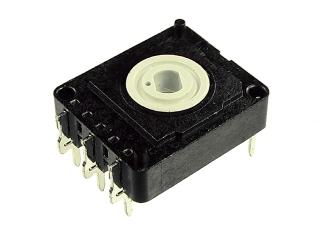
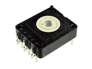
Mechanischer Tastenschalter / Microswitch
large_CRC17-100KA-1-E.JPG
in „Suche Tipp für Encoder“ · Mikrocontroller und Digitale Elektronik · · Fotos
-
PDF
TMC5072_datasheet.pdf
16.3 MICROPLYERSTEPINTERPOLATOR ANDSTAND STILD ETECTION 83 7.1 SENSERESISTORS 48 8 STEALTHCHOP™ 49 17 ABN INCREMENTAL ENCODER INTERFACE 85 8.1 TWO M ODES FORCURRENTREGULATION 49 17.1 ENCODERTIMING 86 8.2 AUTOMATICSCALING 50 17.2 SETTING THENCODER TOM ATCHM OTOR 8.3 FIXEDSCALING 52 RESOLUTION 86 8.4 COMBINING
in „TMC5072 SPI Ansteuerung“ · Mikrocontroller und Digitale Elektronik ·
-
Datei
enc28j60.h
define EDMADSTL (0x14|0x00) #define EDMADSTH (0x15|0x00) #define EDMACSL (0x16|0x00) #define EDMACSH (0x17|0x00) // Bank 1 registers #define EHT0 (0x00|0x20) #define EHT1 (0x01|0x20) #define EHT2 (0x02|0x20) #define EHT3 (0x03|0x20) #define EHT4 (0x04|0x20) #define EHT5 (0x05|0x20) #define EHT6 (0x06|0x20
in „Probleme mit dem myEthernet.kein USART-Signal“ · Mikrocontroller und Digitale Elektronik ·
-
PDF
msp430fr2532.pdf
19FFh–1800h 19FFh–1800h 19FFh–1800h Bootstrap loader (BSL1) Read only 2KB 2KB 2KB 2KB Memory (ROM) 17FFh–1000h 17FFh–1000h 17FFh–1000h 17FFh–1000h Bootstrap loader (BSL2) Read only 1KB 1KB 1KB 1KB Memory (ROM) FFFFFh–FFC00h FFFFFh–FFC00h FFFFFh–FFC00h FFFFFh–FFC00h CapTIvate Libraries and 12KB 12KB 12KB
in „MSP430 Output nur auf zwei von vier Pinnen möglich?“ · Mikrocontroller und Digitale Elektronik ·
-
PDF
emmc.pdf
positive edge and the other bit for the negative edge. For CRC status response output, the CRC status is latched on the positive edge only, and is "Don't Care" on the negative edge. VCC Supply VCC NAND interface (I/F) I/O and NAND Flash power supply. V Supply V
in „Pin-Swap/Cross IC?“ · Mikrocontroller und Digitale Elektronik ·
-
PDF
M16C62_Hardware.pdf
CRC code. The CRC code is a 16-bit code generated for a block of a given data length in multiples of 8 bits. The CRC code is set in a CRC data register each time one byte of data is transferred to a CRC
in „M16C Parallel pinbelegung“ · Mikrocontroller und Digitale Elektronik ·
-
Datei
mci.c
*/ void MCI_CmdProcess( void ) { DWORD MCIStatus; MCIStatus = MCI_STATUS; if ( MCIStatus & MCI_CMD_CRC_FAIL ) { CmdCRCErrCount++; MCI_CLEAR = MCI_CMD_CRC_FAIL; } if ( MCIStatus & MCI_CMD_TIMEOUT ) { CmdTimeoutErrCount++; MCI_CLEAR = MCI_CMD_TIMEOUT; } /* Cmd Resp End or Cmd Sent */ if ( MCIStatus & MCI_CMD_RESP_END
in „LPC2368 SD/MMC interface (not fat, yet)“ · µC & Digital Electronics ·
-
PDF
stm32g030c6.pdf
I 2C-Bus an den Pins PB6/PB7 bzw. PB10/PB11 3.6 Berechnungseinheit für zyklische Redundanzprüfung (CRC) Die CRC-Berechnungseinheit (CRC = Cyclic Redundancy Check) wird verwendet, um einen CRC-Code unter Verwendung eines konfigurierbaren Generatorpolynomwerts und einer konfigurierbaren Größe zu erhalten
in „Muß der STM32G programmiert werden?“ · Mikrocontroller und Digitale Elektronik ·
-
Datei
rfid.c
include <avr/pgmspace.h> #include <avr/eeprom.h> #include <stdlib.h> #include <string.h> #include <util/crc16.h> #include <util/delay.h> #include <avr/boot.h> #include <stdint.h> #include <avr/wdt.h> /*global time/status*/ unsigned char tm[8]; volatile unsigned char failtimeout,tcheck,pulsw,d_bit,d_ready,
in „RFID HTRC110“ · Mikrocontroller und Digitale Elektronik ·
-
PDF
TRW-24G.pdf
PAYLOAD · In Shock-Burst mode payload size is 256 bits minus the following:(Address: 8 to 40 bits. + CRC 8 or 16 bits). · 8 or 16 bits length 4. CRC · The CRC is stripped from the received output data. 14 配置WS2401模組數據時從高位開始。 范例:在ShockBurth的發射模式,以一個通道在2410MHz下以1Mbps Rate傳送。 Bit143 Bit142 Bit141 Bit140 Bit139
-
Datei
iotn814.h
0 /* CRC Source group position. */ #define CRCSCAN_SRC0_bm (1<<0) /* CRC Source bit 0 mask. */ #define CRCSCAN_SRC0_bp 0 /* CRC Source bit 0 position. */ #define CRCSCAN_SRC1_bm (1<<1) /* CRC Source bit 1 mask
in „Attiny417/814/816/817 und avr-gcc, avr-libc“ · Mikrocontroller und Digitale Elektronik ·
-
Datei
final_countdown.asm
RETI RETI RETI RETI RETI RJMP start RETI RETI RETI RETI RETI RETI RETI .def temp1 = r16 .def temp2 = r17 .def temp3 = r18 .def loop1 = r19 .def loop2 = r20 .def ztau = r1 .def taus = r2 .def hund = r3 .def zehn = r4 .def ein = r5 .def konst = r21 .equ temp_lsb = 0x060 .equ temp_msb = 0x061 .equ th_reg =
in „DS1820 convert_t“ · Mikrocontroller und Digitale Elektronik ·
-
Datei
final_countdown.asm
RETI RETI RETI RETI RETI RJMP start RETI RETI RETI RETI RETI RETI RETI .def temp1 = r16 .def temp2 = r17 .def temp3 = r18 .def loop1 = r19 .def loop2 = r20 .def ztau = r1 .def taus = r2 .def hund = r3 .def zehn = r4 .def ein = r5 .def konst = r21 .equ temp_lsb = 0x060 .equ temp_msb = 0x061 .equ th_reg =
in „DS1820 convert_t“ · Mikrocontroller und Digitale Elektronik ·
-
Datei
TEST.asm
10*(Count_Per_C - Count_Remain)) / 16 ; Das Ergebnis liegt dann in Zehntel Grad vor. ; ma1200: lds r17,temp_msb ;Temperaturwert H holen lds r16,temp_lsb ;Temperaturwert L holen ror r17 ror r16 ;LSB abschneiden (Temp_Read) ldi r17,160 ;Wert für höhere Genauigkeit mulsu r16,r17 ;mit 160 multiplizieren movw
in „Vorzeichen Ausgeben“ · Mikrocontroller und Digitale Elektronik ·
-
Datei
LPC407x_8x_177x_8x.h
OTGClkCtrl; }; union { __I uint32_t USBClkSt; __I uint32_t OTGClkSt; }; } LPC_USB_TypeDef; /*------------- CRC Engine (CRC) -----------------------------------------*/ typedef struct { __IO uint32_t MODE; __IO uint32_t SEED; union { __I uint32_t SUM; struct { __O uint32_t DATA; } WR_DATA_DWORD; struct { __O
in „Einstieg LPC4088 QuickStart Board“ · Mikrocontroller und Digitale Elektronik ·
-
Datei
dap_mod_cfg.h
UCHAR aucName [12]; // 12 byte 112=NAME UCHAR ucAttr; // 1 byte 124 UCHAR ucRes; // 1 byte 125 UINT uiCRC; // 2 byte 126=Setup CRC (nicht CRC des Presets !!!) } T_SYN_PRESET; // 128 byte 128=END */ // chorus DAP_MOD_PRESETREMAP ( 97+0, 0x90, PVC_7BIT_UNS, 0x7f) DAP_MOD_PRESETREMAP ( 97+1, 0x91, PVC_7BIT_UNS
in „Konzeptphase für Hobbyprojekt“ · Mikrocontroller und Digitale Elektronik ·
-
Datei
rfm70.h
from IRQ pin, 0 allows //! - 4 : 1 masks MAX_RT (see...) from IRQ pin, 0 allows //! - 3 : 1 enables CRC (forced high when EN_AA != 0) //! - 2 : 0 = 1 byte CRC, 1 = 2 byte CRC //! - 1 : 0 = power down, 1 = power up //! - 0 : 0 = transmit mode, 1 = receive mode #define RFM70_REG_CONFIG 0x00 //! EN_AA :
in „RFM70 Arduino Probleme“ · Mikrocontroller und Digitale Elektronik ·
-
Datei
config.c
während Schlafmodus */ /* 3 nix */ #define en_FLASH (1<<4) /* Flash Interface */ /* 5 nix */ #define en_CRC (0<<6) /* CRC-32 (ethernet) Calculator */ /* 7 nix */ #define en_FSMC (0<<8) /* externer Speichercontroller */ /* 9 nix */ #define en_SDIO (0<<10) /* SD-karten-Interface */ /***** APB1 ************/
in „MINOS - Minos Is No Operating System“ · Projekte & Code ·
-
Datei
config.c
während Schlafmodus */ /* 3 nix */ #define en_FLASH (1<<4) /* Flash Interface */ /* 5 nix */ #define en_CRC (0<<6) /* CRC-32 (ethernet) Calculator */ /* 7 nix */ #define en_FSMC (0<<8) /* externer Speichercontroller */ /* 9 nix */ #define en_SDIO (0<<10) /* SD-karten-Interface */ /***** APB1 ************/
in „Problem mit Clock Configuration beim STM32G031“ · Mikrocontroller und Digitale Elektronik ·
-
Datei
Temperatur_ganz_neu.asm
m8515def.inc" .def count_remain_flash = r13 .def controll = r15 .def temp1 = r16 ;LCD Ausgabe .def temp2 = r17 ;LCD Ausgabe .def temp3 = r18 ;LCD Ausgabe .def delay1 = r19 .def delay2 = r20 .def delay3 = r21 .def kommazahl = r22 ;Kommazahl .def offset = r23 ;ASCII Offset .def buchstabe = r24 ; .def befehl = r25
in „Temperaturauswertung klappt nicht“ · Mikrocontroller und Digitale Elektronik ·
-
PDF
app162__Interfacing_DS1820_in_a_MC_environment_.pdf
shift the bit mask k if(k==0) // if the mask is 0 then go to new ROM { // byte n and reset mask ow_crc(ROM[n]); // accumulate the CRC n++; k++; } } }while(n<8); //loop until through all ROM bytes 0-7 if(m<65||dowcrc) // if search was unsuccessful then lastDiscrep=0; // reset the last discrepancy to 0
in „DS18B20 zu komplizierte Ansteuerung?“ · Mikrocontroller und Digitale Elektronik ·
-
PDF
app162__Interfacing_DS1820_in_a_MC_environment_.pdf
shift the bit mask k if(k==0) // if the mask is 0 then go to new ROM { // byte n and reset mask ow_crc(ROM[n]); // accumulate the CRC n++; k++; } } }while(n<8); //loop until through all ROM bytes 0-7 if(m<65||dowcrc) // if search was unsuccessful then lastDiscrep=0; // reset the last discrepancy to 0
-
Datei
ASLGZ_Logger_OPEN.ino
shift |= 1; reflector >>= 1; i++; } while (i < bits); return shift; } //******************* calculate CRC16-CCITT ****************************** uint16_t crc_one_byte(uint16_t crcR, uint16_t oneByte, uint16_t poly){ oneByte = refUint(oneByte,8); // reflected input oneByte <<= 8; // shift left eight times for(int i=0; i<8; i++){ if((crcR ^ oneByte) & 0x8000) crcR =(crcR << 1)^ poly; else crcR <<= 1; oneByte <<= 1; } return crcR; } //*********************** reset all metervalues ********************** void resetValues(){ FromGrid1=FromGrid2
in „Digitale Stromzähler auslesen und in DB speichern“ · Mikrocontroller und Digitale Elektronik ·
-
PDF
edip240-7.pdf
Y-Pixel, Version, Touchinfo, (V1.3: anz=14; ab V1.4: anz = 21) Nach dem Befehl 'ESC S I' werden interne CRC-ROM, CRC-ROMsoll Informationen vom eDIP gesendet (16-Bit integer Werte LO- HI-Byte) ESC I anz EEP in KB, Version: LO-Byte = Versionsnr. Software; HI-Byte = Hardwarerevisonsbuchstabe (abV1.4) CRC-EEP, CRC-EEPsolTouchinfo: LO-Byte = '-|+' X-Richtung erkannt; HI-Byte = '-|+' Y-Richtung erkannt EEPanz EEPanz: Anzahl benutzter Bytes im EEPROM (3 Byte: LO-, MID- HI-Byte) Antworten ohne Längenangabe (anz)
in „MSP430F149 und EDIP240-7“ · Mikrocontroller und Digitale Elektronik ·
-
Datei
mega128RFA1.h
0x11; sfrb PING=0x12; sfrb DDRG=0x13; sfrb PORTG=0x14; sfrb TIFR0=0x15; sfrb TIFR1=0x16; sfrb TIFR2=0x17; sfrb TIFR3=0x18; sfrb TIFR4=0x19; sfrb TIFR5=0x1a; sfrb PCIFR=0x1b; sfrb EIFR=0x1c; sfrb EIMSK=0x1d; sfrb GPIOR0=0x1e; sfrb EECR=0x1f; sfrb EEDR=0x20; sfrb EEARL=0x21; sfrb EEARH=0x22; sfrw EEAR=0X21
in „ATmega128RFA1“ · Mikrocontroller und Digitale Elektronik ·
-
PDF
349_529-15.pdf
Membran-Kupplungen Metallbalg- Membran- Flach- mit galvanischer Trennung Kupplung kupplung kupplung K 14 K 17/01 K 17/02 K 17/03 18EBN3 K 03 K 18 K 17/06 K 17/04 Nabenbohrungen 6 mm 6 mm 6/10 mm 10 mm 4/4 mm 10 mm 10 mm 6/5 mm 10 mm Kinematischer ± 6” ± 10” ± 40" ± 2” ± 3” Übertragungsfehler* Torsions- Nm Nm
in „Wie entsteht das Sinusförmige Signal eines Drehgebers/ Vermutung“ · Offtopic ·
-
Datei
stm32f103x6.h
CRC_DR_DR_Pos (0U) #define CRC_DR_DR_Msk (0xFFFFFFFFUL << CRC_DR_DR_Pos) /*!< 0xFFFFFFFF */ #define CRC_DR_DR CRC_DR_DR_Msk /*!< Data register bits */ /******************* Bit definition for CRC_IDR register
in „System Workbench für STM32 Anfängerfragen“ · PC Hard- und Software ·
-
Datei
stm32f103xb.h
CRC_DR_DR_Pos (0U) #define CRC_DR_DR_Msk (0xFFFFFFFFUL << CRC_DR_DR_Pos) /*!< 0xFFFFFFFF */ #define CRC_DR_DR CRC_DR_DR_Msk /*!< Data register bits */ /******************* Bit definition for CRC_IDR register
in „System Workbench für STM32 Anfängerfragen“ · PC Hard- und Software ·
-
PDF
STM103.pdf
. . . . . . . . . . . . . . . . . . . . . . . . . . . . . . . . . . . . . . . . . . . . . . . . . 17 2.3.17 Universal synchronous/asynchronous receiver transmitter (USART) . . 17 2.3.18 Serial peripheral interface (SPI) . . . . . . . . . . . . . . . . . . . . . . . . . . . . . . . 17 2.3.19 Controller
in „STM32 2 Versorgungsspannungen?“ · Mikrocontroller und Digitale Elektronik ·
-
PDF
manual_maestro.pdf
CRC-7 polynomial underneath the message so that the LSB of your polynomial is directly below the LSB of your message. 4. If the LSB of your CRC-7 is aligned under a 1, XOR the CRC-7 with the message to
in „Pegelwandler 3.3v -> 5v“ · Mikrocontroller und Digitale Elektronik ·
-
Datei
enc28j60__Problem.txt
Rxstart_init = 0x0000 ' give TX buffer space for one full ethernet frame (~1500 bytes) Rxstop_init = 0x17FE ' receive buffer gets the rest ... Sub Enc28j60init() NextPacketPointer = Rxstart_init 'do bank 0 stuff 'initialize receive buffer '16-bit transfers, must write low byte first 'set receive buffer start
in „ENC28J60 an C-Contro Pro (Atmega128)“ · Mikrocontroller und Digitale Elektronik ·
-
Datei
sdb.txt
------- -------------------- 42 d8 00 3f 98 17 e0 00 00:09:54.777 READ VERIFY SECTOR(S) EXT 42 d8 00 3f 96 17 e0 00 00:09:54.773 READ VERIFY SECTOR(S) EXT 42 d8 00 3f 94 17 e0 00 00:09:54.768 READ VERIFY SECTOR(S) EXT 42 d8 00 3f 92 17 e0 00 00:09
in „Zeigt her eure S.M.A.R.T.-Werte!“ · PC Hard- und Software ·
-
PDF
T83C5121.PDF
FF 03 C0 21 04 00 00 08 07 02 08 02 2D DB (CRC = 2DDBh) FF 03 80 21 02 04 00 0A 03 06 C0 A8 70 01 E3 3D (CRC = E33Dh) FF 03 C0 21 02 01 00 10 02 06 00 00 00 00 05 06 00 00 76 55 49 AC (CRC = 49ACh) The CRC algorithm is the following : **********
in „[V] 1 Stange ältere (ca. 56St) Atmel AT89C5121 mit Interface für Chipkarten/ SIM (9€)“ · Markt ·
-
PDF
T83C5121.PDF
FF 03 C0 21 04 00 00 08 07 02 08 02 2D DB (CRC = 2DDBh) FF 03 80 21 02 04 00 0A 03 06 C0 A8 70 01 E3 3D (CRC = E33Dh) FF 03 C0 21 02 01 00 10 02 06 00 00 00 00 05 06 00 00 76 55 49 AC (CRC = 49ACh) The CRC algorithm is the following : **********
in „[V] noch 1 Stange ältere (60St) Atmel AT89C5121 mit Interface für Chipkarten/ SIM (9€)“ · Markt ·
-
PDF
PWM_Controller_Manual.pdf
Kanal 11 0C PWM Kanal 12 0D PWM Kanal 13 0E PWM Kanal 14 0F PWM Kanal 15 10 PWM Kanal 16 11 PWM Kanal 17 HB 12 PWM Kanal 17 LB 13 PWM Kanal 18 HB 14 PWM Kanal 18 LB 15 Control_Reg 16 PWM_CNTR_ADDR PW18 TWI- Busadressen Register 17 CS_Soft_PWM 18 CS_HW_PWM_16 19 Res_HW_PWM_HB 1A Res_HW_PWM_LB 1B Res_Soft_PWM
in „PWM- Controller 18- Kanal TWI- Bus Proj.“ · Projekte & Code ·
-
Datei
iotn3217.h
0 /* CRC Source group position. */ #define CRCSCAN_SRC0_bm (1<<0) /* CRC Source bit 0 mask. */ #define CRCSCAN_SRC0_bp 0 /* CRC Source bit 0 position. */ #define CRCSCAN_SRC1_bm (1<<1) /* CRC Source bit 1 mask
in „Neue 8-Bit Tinys vorgestellt: 417/814/816/817“ · Mikrocontroller und Digitale Elektronik ·
-
PDF
A500_EA0FP481-43SW-DB.pdf
mit der Breite b und Höhe h (Angaben in Zeichen) 1,1 Display Organisation 480x272: s=1..60; z=1..34/17; 272x480: s=1..34; z=1..60/30 60,17 Formfeed FF (dez:12) ^L Bildschirm wird gelöscht (Hintergrundfarbe) und der Cursor nach Pos.1,1 gesetzt Carriage Return CR (13) ^M Cursor ganz nach links zum Zeilenanfang
in „eDIPTFT43 Ansteuerungsarten“ · Mikrocontroller und Digitale Elektronik ·
-
PDF
msp430fr5729.pdf
0100h 000h–01Fh PMM (see Table 6-15) 0120h 000h–010h FRAM Control (see Table 6-16) 0140h 000h–00Fh CRC16 (see Table 6-17) 0150h 000h–007h Watchdog (see Table 6-18) 015Ch 000h–001h CS (see Table 6-19) 0160h 000h–00Fh SYS (see Table 6-20) 0180h 000h–01Fh Shared Reference (see Table 6-21) 01B0h 000h–001h
in „Implementierung eines ADT7301 an einem MSP430FR5729“ · Mikrocontroller und Digitale Elektronik ·
-
Datei
10.04.MODBUSMasterMAX485_Anemometer.ino
Enable'; High to Transmit, Low to Receive #define Slave_ID 1 #define RX_PIN 16 //RX2 #define TX_PIN 17 //TX2 // instantiate ModbusMaster object ModbusMaster modbus; void preTransmission() { digitalWrite(MAX485_RE_NEG, HIGH); //Switch to transmit data } void postTransmission() { digitalWrite(MAX485_RE_NEG
in „NODEMCU ESP32 Anemometer RS485 MAX485“ · Mikrocontroller und Digitale Elektronik ·
-
Datei
DTU_esp8266_0419_wemos_serial_monitor.txt
(~ 2403 MHz) RF Data Rate = 250 KBPS RF Power Amplifier = PA_MIN RF Low Noise Amplifier = Enabled CRC Length = 16 bits Address Length = 5 bytes Static Payload Length = 32 bytes Auto Retry Delay = 250 microseconds Auto Retry Attempts = 0 maximum Packets lost on current channel = 0 Retry attempts made
in „Wechselrichter Hoymiles HM-xxxx 2,4 GhZ Nordic Protokoll?“ · Mikrocontroller und Digitale Elektronik ·
-
PDF
Atmel-8209-8-bit_AVR_ATmega16M1-32M1-64M1_Datasheet_1_.pdf
20-2. CAN extended frames Dataframe BusIdle 11-bitbaseidentifier 18-bitidentifierextension 4-bitDLC CRC ACK Intermission BusIdle SOF IDT28..18 SRR IDE ID17..0 RTR r1 r0 DLC4..0 0-8bytes 15-bitCRC del.ACK del. 7bits 3bits (Indefinite) Interframe Arbitration Control Data CRC ACK Endof Interframe Space Field
in „Externer Interrupt“ · Mikrocontroller und Digitale Elektronik ·
-
PDF
edip160-7.pdf
...12 BEFEHLE/FUNKTIONENINTABELLENFORM ...................................................... 13 - 17 TOUCHPANEL,TASTENFORMEN......................................................................... 16 - 17 RÜCKANTWORTENDESBEDIENPANELS .................................................................18
in „Bitte um Hilfe bei Befehl an Display eDip160-7“ · Mikrocontroller und Digitale Elektronik ·
-
PDF
edip160-7.pdf
...12 BEFEHLE/FUNKTIONENINTABELLENFORM ...................................................... 13 - 17 TOUCHPANEL,TASTENFORMEN......................................................................... 16 - 17 RÜCKANTWORTENDESBEDIENPANELS .................................................................18
in „String empfangen und auswerten“ · Mikrocontroller und Digitale Elektronik ·
-
Datei
main.cpp
0x10, PHY_SCR = 0x11, MISR1 = 0x12, MISR2 = 0x13, FCSCR = 0x14, RECR = 0x15, BISCR = 0x16, RCSR = 0x17, LEDCR = 0x18, PHY_CR = 0x19, _10BTSCR = 0x1A, BICSR1 = 0x1B, BICSR2 = 0x1C, RESERVED = 0x1D, CDCR = 0x1E, PHY_RCR = 0x1F }; void init_pins() { STM32F107RCT6& stm32 = STM32F107RCT6::get(); GPIO& gpio
in „STM32F107 Ethernet RMII“ · Mikrocontroller und Digitale Elektronik ·
-
PDF
ADE7953.pdf
(LFSR) based generator,startingwith the least significantbit.The 32-bitresult is written tothe CRC register. The CRC is disabled by default andcan beenabled by setting the CRC_ENABLEbit(Bit8) of the CONFIG register Figure 75shows how the LFSR works. The registers shown in (Address 0x102).When thisbitis
in „Leistungsfaktor durch Analog Device neu definiert?“ · Analoge Elektronik und Schaltungstechnik ·
-
PDF
gps-spec-IS_GPS_200J.pdf
17 BITS 15 BITS 16 BITS 16 BITS 21 MSBs DIRECTION OF DATA FLOW FROM SV MSB FIRST 100 BITS 4 SECONDS 201 204 228 249 270 277 c cus-n cuc-n rc-n CRC 24 BITS 21 BITS 21 BITS 7 BITS 24 BITS c - 3 LSBs RESERVED
in „Magisches Auge für GPS-Empfänger“ · Mikrocontroller und Digitale Elektronik ·
-
PDF
_Elmos__981_03.pdf
between end of UART service and start of transmission on EIB bus is variable (faster) bit description CRC: "1": the UART CRC is enabled (not available in analog mode and not at 9.6kBd) "0": the UART CRC is disabled ON1 : ON0 : "-1" or "1-": the UART is switched on "00": the UART is switched off 1) Access
in „Exposed Pad anschließen? (ATSAMD20E18A-MU und ELMOS E981.03)“ · Mikrocontroller und Digitale Elektronik ·
-
Datei
rf22.c
write(0x3c, 'p'); // transmit header 1 rf22_write(0x3d, 'e'); // transmit header 0 rf22_write(0x3e, 17); // packet length rf22_write(0x3f, 'h'); // check header 3 rf22_write(0x40, 'o'); // check header 2 rf22_write(0x41, 'p'); // check header 1 rf22_write(0x42, 'e'); // check header 0 rf22_write(0x43,
-
PDF
78K1PAGE.PDF
memory are retained. Also retained are P 006xh CALLT23 CALLT22 CALLT21 CALLT20 CALLT19 CALLT18 CALLT17 CALLT16 Terminal width : 0.65mm LVI(Low-voltage detector) √ √ the statuses of the output latch and 0 CALLT instruction jump table External interrupt √ √ output buffer of the I/O port. 1 005xh CALLT15
in „Verständnisfrage zu Speicherbelgung in Mikrocontrollern“ · Mikrocontroller und Digitale Elektronik ·
-
PDF
78K1P.PDF
memory are retained. Also retained are P 006xh CALLT23 CALLT22 CALLT21 CALLT20 CALLT19 CALLT18 CALLT17 CALLT16 Terminal width : 0.65mm LVI(Low-voltage detector) √ √ the statuses of the output latch and 0 CALLT instruction jump table External interrupt √ √ output buffer of the I/O port. 1 005xh CALLT15
in „Wie heftet ihr z.B: das Reference Manual von Controllern ab?“ · Offtopic ·