-
PDF
AD538_c.pdf
Real-TimeAnalog a ComputationalUnit(ACU) AD538 FEATURES FUNCTIONAL BLOCK DIAGRAM V m V OUT = V Y Z÷ Transfer Function V X IZ 1 18 A Wide Dynamic Range (Denominator) –1000:1 V 2 25kV RATIO 17 D Simultaneous Multiplication and Division Z Resistor-Programmable Powers and Roots No External Trims Required B 3
in „Wurzeloperation mit Operationsverstärker“ · Analoge Elektronik und Schaltungstechnik ·
-
PDF
AD538_analog_rechnen.pdf
Real-TimeAnalog a ComputationalUnit(ACU) AD538 FEATURES FUNCTIONAL BLOCK DIAGRAM V m V OUT = V Y Z÷ Transfer Function V X IZ 1 18 A Wide Dynamic Range (Denominator) –1000:1 V 2 25kV RATIO 17 D Simultaneous Multiplication and Division Z Resistor-Programmable Powers and Roots No External Trims Required B 3
in „Beschaltung eines analogen Positionssensors“ · Analoge Elektronik und Schaltungstechnik ·
-
PDF
AD538_analog_rechnen.pdf
Real-TimeAnalog a ComputationalUnit(ACU) AD538 FEATURES FUNCTIONAL BLOCK DIAGRAM V m V OUT = V Y Z÷ Transfer Function V X IZ 1 18 A Wide Dynamic Range (Denominator) –1000:1 V 2 25kV RATIO 17 D Simultaneous Multiplication and Division Z Resistor-Programmable Powers and Roots No External Trims Required B 3
in „Zu viel Rauschen bei OPV Schaltung“ · Analoge Elektronik und Schaltungstechnik ·
-
PDF
488.1-1987-NN.pdf
provided for resolving these conflicts. This is accomplished by implementing two types of message transfer over the interface, active transfer and passive transfer. The interface is structured so that in all conflicts between two message values, one of them will be active and the other passive. Messages
in „GPIB Controller“ · Mikrocontroller und Digitale Elektronik ·
-
PDF
24lc32a.pdf
device. 3.0 BUS CHARACTERISTICS 3.5 Acknowledge The following bus protocol has been defined: • Data transfer may be initiated only when the bus is Each receiving device, when addressed, is obliged to not busy. generate an acknowledge signal after the reception of • During data transfer, the data line must
in „Logikanalzyer mit FT232BL“ · Mikrocontroller und Digitale Elektronik ·
-
Datei
VERDRAHT.TXT
low data bus, 3=D7 .. 17=D0. This part of 13,15,17 the bus is used for the command and parameter transfer. It is also used for the low byte in 16-bits data transfers. 4,6,8,10 D8..D15 high data bus, 4=D8 .. 18=D15. This part 12,14,16,18 of the bus is used only for the 16-bits data transfer. 20 - This
in „Retro Fieber: Z80 oder 68000 ?“ · Mikrocontroller und Digitale Elektronik ·
-
PDF
CAN_Bus_Elektor_Optimized.pdf
parts? Layer 7 CAL: CAN DeviceNet SDS Application layeSpecifications Specifications • How are data transfer errors pre- "Application Layer" for industrial vented, recognized, and corrected? Applications • How is the data transfer protocol formed? Layer 3 - 6 Empty !! • How is access to the data transfer
in „CAN mir das einer mal erklären?“ · Mikrocontroller und Digitale Elektronik ·
-
Datei
iic0_-_master_-_c6713b.c
Data Count Register (I2CCNT) */ I2C_I2CCNT_RMK( I2C_I2CCNT_ICDC_DEFAULT//how many data words to transfer 1-65535 ), /* I2C Slave Address Register (I2CSAR) */ I2C_I2CSAR_RMK( I2C_I2CSAR_A_DEFAULT//7 Bit Slave Adress ), /* I2C Mode Register (I2CMDR) */ I2C_I2CMDR_RMK( I2C_I2CMDR_NACKMOD_DEFAULT,//NACK
in „I2C hängt, sendet manchmal nur 7 bit“ · Mikrocontroller und Digitale Elektronik ·
-
PDF
RHP_Compensation.pdf
limitsallowed by the specification,when subjected power stage. The desired result is an open loop transfer to these disturbances. For the diagramn figure1,the transfer function that has high gain and reasonably high bandwidth, and that does not violate Nyquist's stability criterion. Due tounction Gp(s)
in „Tipps Flyback-Regelung?“ · Analoge Elektronik und Schaltungstechnik ·
-
Datei
main.c
word SPI1->DR=data; // send 16 bit word while ( (SPI1->SR & SPI_SR_BSY)); // busy wait for SPI transfer to be finished while ( (SPI2->SR & SPI_SR_BSY)); // busy wait for SPI transfer to be finished WRITE_REG(GPIOB->BSRR,GPIO_BSRR_BS12); // PB12 high ( Chip select for SPI) data++; ITM_SendChar('b');
in „Frage: STM32F103 beide SPI benutzen“ · Mikrocontroller und Digitale Elektronik ·
-
 Bild
Bild
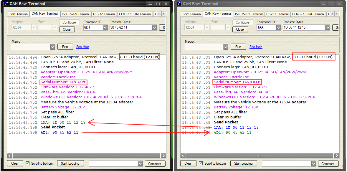
Zwei Screenshots der CAN Raw Terminal Software
CAN Raw Terminal Adapter: J2534 Port: Configure Close Command ID: 6D1 Transmit Bytes: 90 45 62 11 Macro: Run See Help Open J2534 adapter, Protocol: CAN Raw, 83333 baud (12.0µs) CAN ID: 11 and 29 bit, CAN Filter: None ConnectFlags: CAN_ID_BOTH Adapter: OpenPort 2.0 J2534 ISO/CAN/VPW/PWM Vendor: Tactrix Inc. Serial Number: TANIOFr Firmware Version: 1.17.4877 Pass-Thru API Version: 04.04 Windows DLL Version: 1.02.4820 Jul 6 2016 17:20:04 Measure the vehicle voltage at the J2534 adapter Battery voltage: 12.20V Set pass ALL filter Clear Rx buffer 1AA: 1D 00 11 12 13 Send Packet 6D1: 90 45 62 11
in „Neuer CAN Bus Analyzer mit billigen Adaptern“ · Fahrzeugelektronik · · Screenshots

-
 Bild
Bild
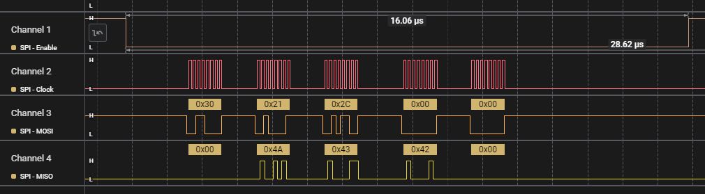
SPI Protokoll Messung am Logikanalysator
Channel 1 SPI - Enable 16.06 µs 28.62 µs L H Channel 2 SPI - Clock L H 0x30 0x21 0x2C 0x00 0x00 Channel 3 SPI - MOSI H L 0x00 0x4A 0x43 0x42 0x00 Channel 4 SPI - MISO H L
in „Arduino Uno R4: Besonderheiten und Abhilfen“ · Mikrocontroller und Digitale Elektronik · · Oszi-Bilder

-
Datei
dma.c
LPC_GPDMACH0->DMACCConfig = 0; if ( DMAMode == M2P ) //memory to peripheral { /* Ch0 set for M2P transfer from memory to DAC. */ LPC_GPDMACH0->DMACCSrcAddr = DMA_SRC; LPC_GPDMACH0->DMACCDestAddr = DMA_DST; /* The burst size is set to 1, source and dest transfer width is 32 bits(word), src addr increment
in „DAC+DMA LPC1769“ · Mikrocontroller und Digitale Elektronik ·
-
Datei
usart2dmactrl.c
------------------- */ void DMA1_Channel6_IRQHandler(void) // USART2_RX { /* Test on DMA Stream Transfer Complete interrupt */ if (DMA_GetITStatus(DMA1_IT_TC6)) { /* Clear DMA Stream Transfer Complete interrupt pending bit */ DMA_ClearITPendingBit( DMA1_IT_TC6); pstUsart2Ctrl->flagRx = 1; // new data
in „STM32F303 USART2 DMA1 funktioniert halblebig ?“ · Mikrocontroller und Digitale Elektronik ·
-
Datei
usart2dmactrl.c
------------------- */ void DMA1_Channel6_IRQHandler(void) // USART2_RX { /* Test on DMA Stream Transfer Complete interrupt */ if (DMA_GetITStatus(DMA1_IT_TC6)) { /* Clear DMA Stream Transfer Complete interrupt pending bit */ DMA_ClearITPendingBit( DMA1_IT_TC6); pstUsart2Ctrl->flagRx = 1; // new data
in „STM32F303 USART2 DMA1 funktioniert halblebig ?“ · Mikrocontroller und Digitale Elektronik ·
-
PDF
SwissArmyKnife.pdf
phase response. The equalizer has a response located at ±f s4 . The fil- is located at 0 Hz (dc). transfer function of H 1,eq(z) = ter’s transfer function is H ac) = (−R + z −1)/(1 − Rz −1 ). 1/(1 − αz −2 ), resulting in two poles Bandpass Filter at f /4 These networks can be used as √ s located at z =
in „The Swiss Army Knife of Digital Networks“ · Digitale Signalverarbeitung / DSP / Machine Learning ·
-
PDF
OTM3225A.pdf
transfer mode for 18-bit GRAM data For 16-bit data bus interface mode: TRI=0: 1 time transfer mode for 16-bit GRAM data. TRI=1: 2 time transfer mode for 18-bit GRAM data ★Note: Set TRI=0, when using neither
in „[V]erkaufe TFT 2.8" und TFT 2.4" mit adapter PCB“ · Markt ·
-
Datei
ioat91sam7se512.h
) Transmitter Transfer Enable AT91C_PDC_TXTDIS EQU (0x1 << 9) ;- (PDC) Transmitter Transfer Disable // - -------- PDC_PTSR : (PDC Offset: 0x24) PDC Transfer Status Register -------- // - ********************************
in „AT91SAM7SE512 Einstieg“ · Mikrocontroller und Digitale Elektronik ·
-
PDF
HD66773.pdf
10 9 8 7 6 5 4 3 2 1 0 Figure 13 8-bit interface/SPI (transfer two times/pixel) First transfer Second transfer DB DB DB DB DB DB DB DB DB DB DB DB DB DB DB DB 17 16 15 14 13 12 11 10 17 16 15 14 13 12 11 10 Instruction bit IB IB IB IB IB IB IB IB IB IB IB IB
in „The Siemens S65 132x176, 65536 color display with AVR“ · Projekte & Code ·
-
PDF
HD66773.pdf
10 9 8 7 6 5 4 3 2 1 0 Figure 13 8-bit interface/SPI (transfer two times/pixel) First transfer Second transfer DB DB DB DB DB DB DB DB DB DB DB DB DB DB DB DB 17 16 15 14 13 12 11 10 17 16 15 14 13 12 11 10 Instruction bit IB IB IB IB IB IB IB IB IB IB IB IB
in „The Siemens S65 132x176, 65536 color display with AVR“ · Projekte & Code ·
-
PDF
pc814.pdf
PC824 2-channel type ) Primarysidemark P 6 PC844 (4-channel type ) 1 2 0.9± 0.2 1 2 4. Current transfer ratio ± 0.3 1.2 CTR : MIN. 20% at I F = ± 1mA, V = 5VCE 5. Recognized by UL, file No. E64380 ±0.5 7.62 ± 0.3 P . 4.58 Applications T ± . . 1. Programmable controllers 0 3 . 0.26± 0.1 2. Telephone
in „Optokoppler Problem“ · Mikrocontroller und Digitale Elektronik ·
-
Datei
0001-WS2812-fix-too-short-reset-pulse.patch
DMA_LEDS_PER_HALFBUFF 1 #define DATA_LEN(n) ((n) * WS2812_BIT_PER_LED) // number of total bytes to transfer data #define PAUSE_LEN (WS2812_PAUSE_LEN) // number of total bytes to transfer pause -#define DMA_BUF_LEN (2 * DMA_LEDS_PER_HALFBUFF * WS2812_BIT_PER_LED) // DMA buffer length: 2 LEDs +#define DMA_BUF_LEN
-
Datei
kk_sd_cmd25_write.h
regVal; abfr_busy(); switch(DMA_STATUS){ case(1): if(DMA_zl_blocks--){ DMA0_from_buffer_to_SSP0_transfer(0,516,0xfc); }else{ // DMA_STATUS=2; // DMA3_transfer_from_SSP0_to_buffer(32); } break; case(2): DMA_STATUS=DMA_STATUS_end; xchg_spi(0xfd); break; }//switch return; } void DMA0_from_buffer_to_SSP0
-
Datei
main.c
define IODIRA 0x00 #define GPIOA 0x12 #define MCP_DDR SPI_DDR #define MCP_PORT SPI_PORT void spi_transfer(uint8_t data) { SPDR = data; while(!(SPSR & (1<<SPIF))); } void mcp_write(uint8_t addr, uint8_t reg, uint8_t data) { MCP_PORT &= ~(1<<SS); spi_transfer(addr); spi_transfer(reg); spi_transfer(data)
in „SPI mit Attiny 841 und MCP23S17“ · Mikrocontroller und Digitale Elektronik ·
-
PDF
vhdl.pdf
synchronous resets Check synthesis results Hardware Design with VHDL VHDL for Synthesis Register Transfer Level Register Transfer Level (RTL) A Module may consist of Pure combinational elements Storage elements Mixture of combinational and storage elements Use RTL for shift registers, counters Finite
-
PDF
AN_165_Establishing_Synchronous_245_FIFO_Communications_using_a_Morph-IC-II.pdf
then read the status lines of the slave and respond by setting the control lines to allow for the transfer of data from the slave to the master. In a similar manner the master device can transfer synchronous 245 data to the other slave device. Here the master is synchronised to clkout of the receiving
-
Datei
i2c.c
} //=============================================================================== // I2C_ReadTransfer - initiate a read transfer on the I2C bus // // Initiates a read transfer on the I2C bus. // If a register address is specified (<addressLength> != 0) a write without a stop // condition will be initiated
in „STM32F4 Discovery mit I2C-Bus EEPROM“ · Mikrocontroller und Digitale Elektronik ·
-
Datei
setup.c
define NULL ((void *)0) #endif #define LOW 0 #define HIGH 1 #define false 0 #define true 1 // SPI transfer 1 byte and return the result uint8_t spi_transfer(uint8_t data) { USIDR = data; USISR = _BV(USIOIF); // clear flag while ( (USISR & _BV(USIOIF)) == 0 ) { USICR = (1<<USIWM0)|(1<<USICS1)|(1<<USICLK
in „Problem Linken von nRF24 Multi Network mit AVR Studio“ · Mikrocontroller und Digitale Elektronik ·
-
Datei
W5500_Register_LoopBackTest.c
FDM1) // BSB = %00000, RW=0(read), OM =%10 uint8_t spi_reg; CS_W5500_LOW; // CS=0, SPI start SPI_Transfer (uint8_t)(addr >> 16); // without CS! SPI_Transfer (uint8_t)(addr >> 8); // without CS! SPI_Transfer ( (uint8_t)addr | (OPMODE_SREAD) ); // without CS! spi_reg = SPI_Transfer (0); /* dummy write *
in „Wiznet W5500 Datenübertragung via Ethernet“ · Mikrocontroller und Digitale Elektronik ·
-
PDF
scc1300_d02_datasheet-extensive-v1.0.4.pdf
...................................................................................12 4.2.1 SPI Transfer.........................................................................................................................12 4.2.2 SPI Transfer Parity Mode...........................................
in „SCC1300 Gyrosensor auslesen“ · Mikrocontroller und Digitale Elektronik ·
-
Datei
USI_SPI_SLAVE.asm
follows from here PCINT: in SREG_SAVE,SREG push r16 sbic USI_SPI_PORT-2,usi_SPI_CS rjmp usi_spi_transfer_end usi_spi_transfer_start: sbi GPIOR0,SPI_ON ; SPI Auswertung einschalten in r16,USI_SPI_PORT-1 sbr r16,(1<<usi_SPI_DO) out USI_SPI_PORT-1,r16 rjmp pcint_end usi_spi_transfer_end: cbi GPIOR0,SPI_ON
in „SPI Kopplung von ATmega8 und ATtiny 2313“ · Projekte & Code ·
-
Datei
USI_SPI_SLAVE.asm
follows from here PCINT: in SREG_SAVE,SREG push r16 sbic USI_SPI_PORT-2,usi_SPI_CS rjmp usi_spi_transfer_end usi_spi_transfer_start: sbi GPIOR0,SPI_ON ; SPI Auswertung einschalten in r16,USI_SPI_PORT-1 sbr r16,(1<<usi_SPI_DO) out USI_SPI_PORT-1,r16 rjmp pcint_end usi_spi_transfer_end: cbi GPIOR0,SPI_ON
in „[ASM] USI tiny SPI Slave im Interrupt Mode“ · Projekte & Code ·
-
Datei
bootloaderV1.a51
code_3B1B: ; add A, #0FEh ; jz EP2InTransfer add A, #0F2h ; jz EP0Setup add A, #02Eh ; jz EP2OutTransfer Xjmp break ;copy the bulkpacket to the cmdbuffer EP2OutTransfer: ; jb U_TOG_OK, code_3B30 ; Xjmp break code_3B30: ; mov rLen, USB_RX_LEN
in „uC für 0,20€ CH552 / CH554 von WCH Billig Micro mit USB Funktion, Chip vorstellung“ · Mikrocontroller und Digitale Elektronik ·
-
PDF
tmp275.pdf
the status of the address pins, but does not reset. If the second byte is 00000110, Start Data Transfer: A change in the state of the SDA line, the TMP275 latches the status of the address pins and from HIGH to LOW, while the SCL line is HIGH, defines a START condition. Each data transfer is initiated
in „Abmessungen Datenblatt“ · Mikrocontroller und Digitale Elektronik ·
-
PDF
pc817.pdf
PC817P TUV (VDE0884 ) approved type is also available as an option. Features Applications 1. Current transfer ratio 1. Computer terminals (CTR: MIN. 50% at I = 5mA F ,V CE=5V) 2. System appliances, measuring instruments 2. High isolation voltage between input and 3. Registers, copiers, automatic vending output
in „Optokoppler schaltet nicht“ · Analoge Elektronik und Schaltungstechnik ·
-
PDF
24C64.pdf
CHARACTERISTICS The following bus protocol has been defined: 2.1 A0, A1, A2 Chip Address Inputs Data transfer may be initiated only when the bus The A0,A1,A2 inputs are used by the 24xx64 for multi- is not busy. ple device operation. The levels on these inputs are During data transfer, the data line must
in „Merkwürdiger 24C64N“ · Mikrocontroller und Digitale Elektronik ·
-
Datei
TFT_ILI9163C.cpp
SPI1.beginTransaction(ILI9163C_SPI); digitalWriteFast(_rs,LOW); digitalWriteFast(_cs,LOW); SPI1.transfer(c); digitalWriteFast(_cs,HIGH); SPI1.endTransaction(); } else { SPI.beginTransaction(ILI9163C_SPI); digitalWriteFast(_rs,LOW); digitalWriteFast(_cs,LOW); SPI.transfer(c); digitalWriteFast(_cs,HIGH
in „Maiskolben Lötstation Display steht Kopf“ · Mikrocontroller und Digitale Elektronik ·
-
PDF
Samsung_Service_Manual_clx4195n.pdf
from www.Manualslib.com manuals search engine 2. Product specification and description 2.2.4.2. Transfer Roller The transfer roller unit is assembled to the rear cover. The transfer roller delivers the toner of the OPC drum to the paper. 2.2.4.3. Drive Unit This machine has the Main Drive Unit and Feed
in „Drucker Samsung CLX-4195FW: Display hängt“ · PC Hard- und Software ·
-
Datei
mtest_main.c
tbldata_requ.u8.d2, tbldata_requ.u8.d3, tbldata_requ.u8.d4, tbldata_requ.u8.d5); dump_tab( ); result = TBL_Transf_Start ( tbldata_requ, &tbldata_resp ); printf("TBL_Transf_Start: result %x\n", result); dump_tab( ); printf("response: %2x %2x %2x %2x \n", tbldata_resp.u8.d2, tbldata_resp.u8.d3, tbldata_resp.u8.d4, tbldata_resp.u8.d5); tbldata_requ.u32 = 0x11223344; result = TBL_Transf_Cont ( tbldata_requ, &tbldata_resp ); printf("TBL_Transf_Cont: result %x\n", result); dump_tab( ); printf("response: %x %x %x %x \n", tbldata_resp.u8.d2, tbldata_resp.u8.d3, tbldata_resp.u8.d4, tbldata_resp.u8
in „Modultests mit scanf“ · Mikrocontroller und Digitale Elektronik ·
-
PDF
155008-da-01-en-8X_DAC_AD7808BRZ_SO24W.pdf
re- Table VIII shows the offset binary transfer function for the Main quired if the complete transfer function needs to be offset DAC. around the V point. Table VII and Figure 23 show the ana- BIAS Table VIII. Offset Binary Code Table for Main
in „DAC AD7808 wie register setzen“ · Mikrocontroller und Digitale Elektronik ·
-
PDF
155008-da-01-en-8X_DAC_AD7808BRZ_SO24W.pdf
re- Table VIII shows the offset binary transfer function for the Main quired if the complete transfer function needs to be offset DAC. around the V point. Table VII and Figure 23 show the ana- BIAS Table VIII. Offset Binary Code Table for Main
in „DAC AD7808 Datenübertragung mit ATMega16 klappt nicht“ · Mikrocontroller und Digitale Elektronik ·
-
PDF
Driver_Library_user_guide.pdf
functions mentioned so far are used only once or infrequently to set up the uDMA channel and transfer. In order to set the transfer addresses, transfer size, and transfer mode, use the function uDMAChannelTransferSet(). This function must be called for each new transfer. Once everything is set up,
in „I2C Display Steuern“ · Mikrocontroller und Digitale Elektronik ·
-
PDF
20120224183241077.pdf
CB CB CB CB CB CB 15 14 13 12 11 10 9 8 7 6 5 4 3 2 1 0 80-system 9-bit interface Figure 6-5 1 Transfer 2 Transfer DB DB DB DB DB DB DB DB DB DB DB DB DB DB DB DB DB DB 17 16 15 14 13 12 11 10 9 17 16 15 14 13 12 11 10 9 Serial interface Data Transfer Format Transfer Start Transfer end CS (input) CB
in „Handydummy (Attrappe)mit richtigem Display - Sony Ericsson Vivaz“ · Mikrocontroller und Digitale Elektronik ·
-
Datei
4094.c
define sr4094_set(pin) SR4094_##pin##_PORT |= (1 << SR4094_##pin##_BIT) static inline void sr4094_transfer_start(void) { sr4094_clear(STROBE); } static inline void sr4094_transfer_end(void) { sr4094_set(STROBE); } static void sr4094_put_byte(uint8_t data) { uint8_t mask = 0x80; do { if (data & mask) sr4094
in „Ansteuerung eines CD4094-Shiftregisters“ · Mikrocontroller und Digitale Elektronik ·
-
Datei
daWandlerDirekt.c
uint16_t Short; uint8_t Byte[2]; } ushort; volatile uint8_t flg = 0; //prototypen unsigned char spi_transfer(unsigned char); void update(); void init(); int main() { init(); while(1){ if (flg == 1){ cli(); update(); flg = 0; sei(); } } return 0; } //Updates den MCP4921 void update() { ushort value; value.Short
in „atmega16 und DA-Wandler MCP4921“ · Mikrocontroller und Digitale Elektronik ·
-
Datei
SMBus0.c
Receiver: Slave address + READ gesendet. NACK empfangen. // Transfer wird wiederholt. case STAT_SLARN: STA = 1; // Restart transfer break; // Master Receiver: Datenbyte empfangen. ACK gesendet. // For a READ: receive each byte from the slave. if this is the last //
in „SMBus0 Kommunikation zwischen zwei 8051 F120 funktioniert nicht“ · Mikrocontroller und Digitale Elektronik ·
-
PDF
gpib_02.pdf
CAN BE CONNECTED ON THE TOP OF ANOTHER. female male In a star connected Consecutively The max. transfer rate 1 Mbyte/sec can be reached only when the total length of the bus cable is no more than 15 m with the average interdevice cable 1 m or less! The maximum data transfer rate, of course, depends
in „HPIB -> Gerät empfängt nichts“ · Mikrocontroller und Digitale Elektronik ·
-
PDF
A500_KB357NT_V6__1_.pdf
Current IR VR=4V - - 10 uA -7 Output Collector dark current ICEO Vce=20V IF=0 - - 10 A Current transfer ratio CTR IF=5mA Vce=5V 50 - 600 % Collector-emitter saturation voltagVCE (sat) I=20mA I C=1mA - - 0.2 V Transfer charact- Rise time tr - 4 18 uS eristics Response Vce=2V I C=2mA time Fall time tr
in „Drehzahlmesser mit Mega8“ · Mikrocontroller und Digitale Elektronik ·
-
Datei
vfifo_signals.vhdl
m_axi_awburst : OUT STD_LOGIC_VECTOR(1 DOWNTO 0); -- Art des Burst; immer gesetzt auf inkrementierte Transfer m_axi_awlock : OUT STD_LOGIC_VECTOR(0 DOWNTO 0); -- Lock Type; immer 0 m_axi_awcache : OUT STD_LOGIC_VECTOR(3 DOWNTO 0); -- Cache Typ; immer 0 m_axi_awprot : OUT STD_LOGIC_VECTOR(2 DOWNTO 0); -- Protection
in „FIFO für Videodaten ohne Prozessor (Spartan 6)“ · FPGA, VHDL & Co. ·
-
PDF
Optokoppler.pdf
Current IR VR=4V - - 10 uA -7 Output Collector dark current ICEO Vce=20V IF=0 - - 10 A Current transfer ratio CTR IF=5mA Vce=5V 50 - 600 % Collector-emitter saturation voltagVCE (sat) I=20mA I C=1mA - - 0.2 V Transfer charact- Rise time tr - 4 18 uS eristics Response Vce=2V I C=2mA time Fall time tr
in „S0 Ausgang wird von Gerät nicht erkannt, falscher OK?“ · Mikrocontroller und Digitale Elektronik ·