-
PDF
83c185.pdf
(PHY) Datasheet Table 2.1 LAN83C185 64-PIN TQFP Pinout PIN NO. PIN NAME PIN NO. PIN NAME 1 GPO0/MII 33 RX_DV 2 GPO1/PHYAD4 34 RX_CLK 3 GPO2 35 RX_ER/RXD4 4 MODE0 36 VSS6 5 MODE1 37 TX_ER/TXD4 6 MODE2 38 TX_CLK 7 VSS1 39 TX_EN
-
Datei
enc28j60.c
_REG_ERXNDH, hi8(ENC28J60_RX_BUFFER_END ), //end hi //rx ptr: //ENC28J60_REG_ERDPTL, lo8(ENC28J60_RX_BUFFER_START+1), //ENC28J60_REG_ERDPTH, hi8(ENC28J60_RX_BUFFER_START+1), //setup bank2: (see microchip datasheet p.36) //1.) clear the MARST bit in MACON2. ENC28J60_REG_MACON2, 0x00, //2.) mac rx enable, activate pause control frame support ENC28J60_REG_MACON1, ((1<<ENC28J60_BIT_MARXEN)|(1<<ENC28J60_BIT_RXPAUS)|(1<<ENC28J60_BIT_TXPAUS)), //3.) setup MACON3
in „ENC28J60 correct value of PHLCON and mirrored registers“ · Mikrocontroller und Digitale Elektronik ·
-
Datei
main.c
PIN 22 // Output Port of the Heartbeat // RFID Reader PIns // Soft uArt #define SOFT_TX LATBbits.LATB2 //RB2//pin 23 TX #define SOFT_RX LATBbits.LATB1 //RB1//pin24 RX /** Function Declarations *************************************/ // MP3 Player UART //Stepp Motor UART void initUART1(int pbClk); // Function
in „PIC32 sendet nur 0x00 über UART (MPLABX)“ · Mikrocontroller und Digitale Elektronik ·
-
PDF
LabVIEW_-_USB-6800_-_1.pdf
anzugeben. Das ist hier aber bei der Angabe der maximalen Differenzspannungen nicht der Fall, Abb.2.3: Fall A: Fall B: AI+ +2,5 V -2,5 V “±5 V“ -2,5 V +2,5 V AI- AI+ und AI- sind die beiden Analog-Eingänge zwischen denen die Differenz- eingangsspannung gemessen werden soll. Abb.2.3: Die differentielle
in „LabVIEW - USB6008 - Ohmmeter, Thermometer (KTY81), Oszilloskop“ · Softwareentwicklung ·
-
PDF
MPPT_charger_20A.pdf
PB3 39 SPI1_SCK 100n S 56k BOOT0 < 0.69 V 13 40 2 Press SW1 < 0.51 s USART2_RX 14 PA3 PB4 41 SPI1_MISO DAC PA4 PB5 SPI1_MOSI USB bootloader: V_REF 15 PA5 PB6 42 I2C1_SCL BOOT0 > 1.61 V B 16 43 GND GND GND GND Press SW1 > 1.47 s B V_BAT PA6 PB7 I2C1_
in „EMV-Test DC/DC - Verbesserungsvorschläge gesucht“ · Analoge Elektronik und Schaltungstechnik ·
-
 Bild
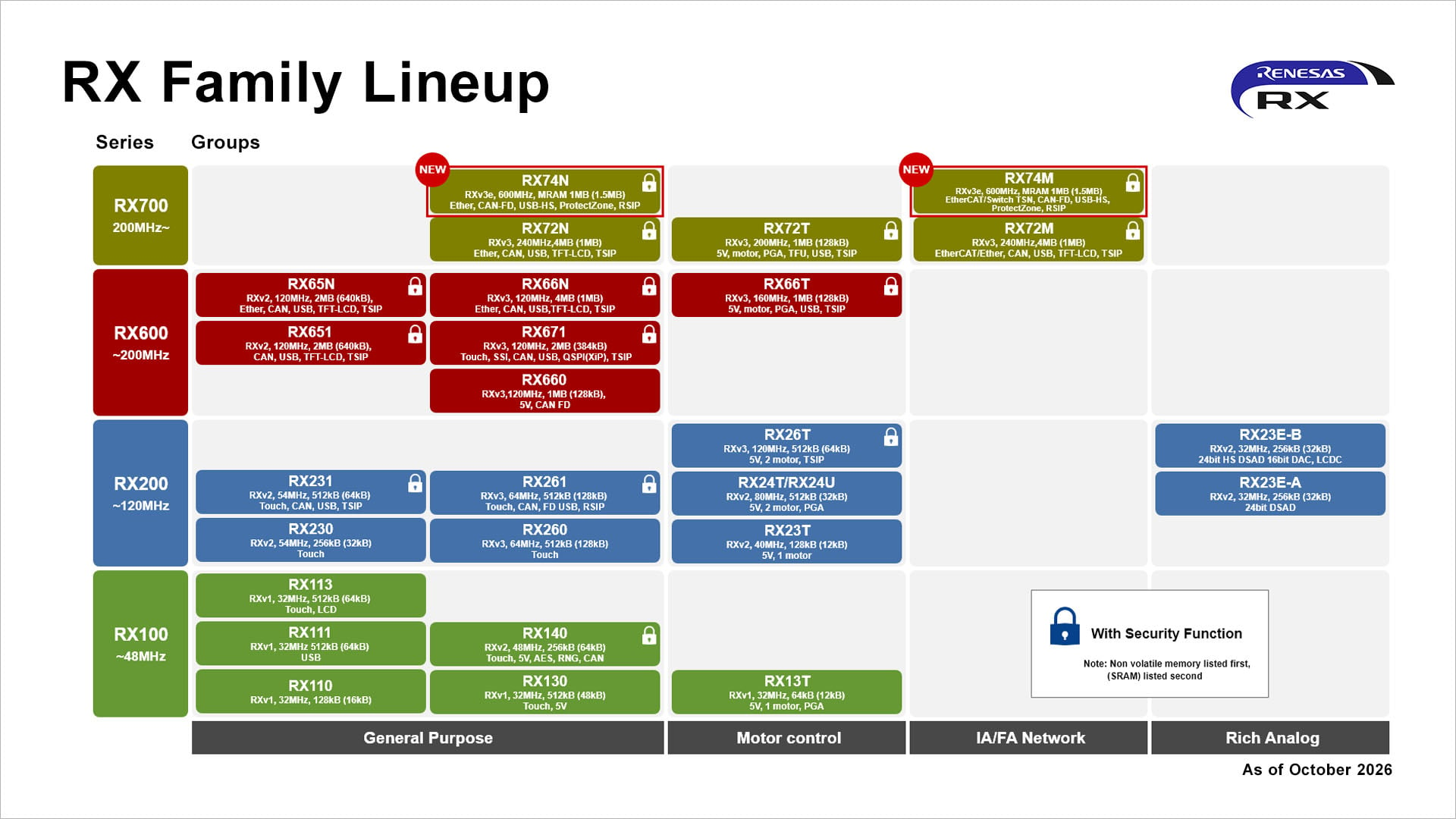
Produktübersicht Renesas RX Family Lineup Mikrocontroller
RX Family Lineup Series Groups RX700 200MHz- RX600 ~200MHz RX200 ~120MHz RX100 ~48MHz NEW RX74N RX30, 600MHz, MRAM 1MB (1.5MB) EBI/CAN, FD, USB, HS, Protections, RSIP RX65N RX2, 120MHz, 64KB (64KB) EBI,
in „Espressif startet Verkauf von Mosaico, Arduino professionalisiert App Lab, Weltraumelektronik uvam“ · Mikrocontroller und Digitale Elektronik · · Diagramme
-
Datei
MD_NMRA_DCC.c
2] & (1<<0) && decoder.dcc.RX[2] & (1<<2)) decoder.dcc.RX[2] &= ~(1<<2); } #endif //if cv1 (addr short) is written, we will reset the cv 29 long adress bit //if cv17/18 (long address) is written, we will
in „FULL NMRA DCC Library, Encoder, Generator, Bremsmodul“ · Projekte & Code ·
-
PDF
CY3272_Schematic.pdf
1 2 3 4 5 6 A A U_3-Filters U_2-PLC10_Interface 3-Filters.SchDoc 2-PLC10_Interface.SchDoc J7 RX RX L 1 F1 TX TX LINE TXDISABLE TXDISABLE B 2.0A NEUTRAL B N 2 1 D1 430V U_4-PowerSupply 4-PowerSupply.SchDoc
in „Power Line bzw. Power LAN im Selbstbau“ · Haus & Smart Home ·
-
PDF
BTT_SKR_V1.4-SCH.pdf
CLS 0 0 . S S I T N . L 1 O S E0CS R12 22R RV7 120R E0-RX MOT_SCK 8 7 M1 G E1-DIR R13 1K Y- +5V X X c 1 1 0 C C C 1 1 1 S c K S S C SI O E1CS R15 22R RV8 120R E1-RX E1-RX 6 5 M2 2B 2B 6 E1-STP 1 +5V R16 10K DC3.3V R T U P E E Z Y X E E E O D U 3 C I - - - -
in „Induktiven Sensor (6-36V) an Microcontroller/Mainboard anschließen“ · Mikrocontroller und Digitale Elektronik ·
-
PDF
BTT_SKR_V1.4SCH.pdf
CLS 0 0 . S S I T N . L 1 O S E0CS R12 22R RV7 120R E0-RX MOT_SCK 8 7 M1 G E1-DIR R13 1K Y- +5V X X c 1 1 0 C C C 1 1 1 S c K S S C SI O E1CS R15 22R RV8 120R E1-RX E1-RX 6 5 M2 2B 2B 6 E1-STP 1 +5V R16 10K DC3.3V R T U P E E Z Y X E E E O D U 3 C I - - - -
in „3D-Drucker, Mainboard-Lüfteranschluss erweitern“ · Mikrocontroller und Digitale Elektronik ·
-
Datei
rfm70.h
receive addresses of data pipes 2 .. 5. #define RFM70_REG_RX_ADDR_P1 0x0B //! RX_ADDR_P2 : receive address for data pipe 2, 1 byte // //! This is the LSB of the receive address for data pipe 2. //! The higher bytes are copied from the
in „RFM70 Arduino Probleme“ · Mikrocontroller und Digitale Elektronik ·
-
PDF
5_-_STM32F_Connectivity_Line.pdf
and the 512-byte SRAM memory. c C Master Control Master Status v N e • CAN 2: Slave bxCAN start filter bank number n[27:1] is Tx Status RxFIFO0 Status C . configurable by SW. Interrupt Enable RxFIFO1 Status o B e Bit Timing Error Status S T M 3 2S e m in a rN o v e m b e r2 0
in „STM32: Timer funktioniert nicht“ · Mikrocontroller und Digitale Elektronik ·
-
Datei
Master.cpp
i < DAQ_PIPE_TX_BUFFERSIZE; i++) tx_frame[i] = 0; // Set CS DAQ_SET_CS(); // Set DMA Rx stream DMA2_Stream2->NDTR = (uint16_t)3; DMA2_Stream2->M0AR = (uint32_t)&rx_frame; // Enable DMA Rx DMA2_Stream2->CR |= (uint32_t)DMA_SxCR_EN; // Enable SPI Rx SPI1->CR2 |= (uint16_t)SPI_I2S_DMAReq_Rx
in „2 STM32F4 SPI Master/Slave FullDuplex“ · Mikrocontroller und Digitale Elektronik ·
-
PDF
Schematic_PCB.pdf
11 9_PWM_OUT1C 16_A2_RX4_SCL1 38 12 10_PWM_CS_MQSR 15_PWM_A1_RX3_SPDIF< 37 LED1 13 36 B T676RGLED 14 11_PWM_MOSI_CTX114_PWM_A0_TX3_SPDIF> 35 B 15 12_PWM_MISO_MQSL 13_PWM_SCK_CRX1_LED 34 R1 3V3 GND GND GND 220 16 24_PWM_A10_TX6_SCL2 41_A1_MIS01 33 17 25_PWM_A11_RX6_SDA2 40_A16_CS1 32 220 GND 18 26_A12_MOSI1 39_DAT2_TX5 31 R2 19 30 20 27_A13_SCK1 38_DAT3_RX5 29 21 28_PWM_RX7 37_PWM_CMD_SCK2 28 29_PWM_TX7 36_PWM_CLK_CS2 22 30_CRX3
in „RJ45 Magnetics Teensy 4.1“ · Analoge Elektronik und Schaltungstechnik ·
-
Datei
CAN.c
OneShotMode.disabled, ClkOut.enabled, ClkPre = 8 (3MHz), Abat = 0 write_MCP(CNF1, 0x05); // BRP = (0,5µs * 24MHz / 2) - 1 = 5 write_MCP(CNF2, 0xB8); // PrSeg = 1tQ, PhSeg1 = 8 tQ, PhSeg2BTL = 1 write_MCP(CNF3, 0x05); // PhSeg2 = 6tQ // Masken und Filter setzen write_MCP(CANCTRL, 0x47); // Mode.Loopback, sonst gleiche
in „*CAN Baudrate Berechnung*“ · Mikrocontroller und Digitale Elektronik ·
-
Datei
CAN.c
OneShotMode.disabled, ClkOut.enabled, ClkPre = 8 (3MHz), Abat = 0 write_MCP(CNF1, 0x05); // BRP = (0,5µs * 24MHz / 2) - 1 = 5 write_MCP(CNF2, 0xB8); // PrSeg = 1tQ, PhSeg1 = 8 tQ, PhSeg2BTL = 1 write_MCP(CNF3, 0x05); // PhSeg2 = 6tQ // Masken und Filter setzen write_MCP(CANCTRL, 0x47); // Mode.Loopback, sonst gleiche
in „CAN-Bus am Atmega 8“ · Mikrocontroller und Digitale Elektronik ·
-
PDF
nRF24L01_.pdf
T40X:00,40,16,AE,FD,AE,94,89,8E,A4,39,74,F3,D7,B0,74,D0,22,EB,ED,09,46,62,E4,9A T40X:00,40,02,FF,0A RX:00,FF,12,FE,0A,D7,D5,85,52,2C,FF,B0,8E,34,F5,66,A6,38,02,CA,C8 Key,55,E5,8E,D0,F9,C4,BF,1C,B0,05,2F,08,BE,5E,E8,91 Autsch! Wie gut das der Serialmanager
in „Repeating und Routing Netzwerk mit Arduino und nRF24L01+“ · Projekte & Code ·
-
Datei
usart.c
include <avr/io.h> volatile unsigned int buffercounter = 0; volatile uint8_t u8_Uebergabe //char usart_rx_buffer[BUFFER_SIZE]; char *rx_buffer_pointer_in = &usart_rx_buffer[0]; char *rx_buffer_pointer_out = &usart_rx_buffer[0]; //---------------------------------------------------------------------------
in „Interrupt Variable übergeben“ · Mikrocontroller und Digitale Elektronik ·
-
PDF
rudi_____RX-V4A_TSR-400.pdf
9 1 4 4 G TC7MBL3257CFK 2-Bit, Dual Supply, Bus Transceiver 0.1/10 P1RX0M 9 100 VSS R37 DGND0 R 1B2 2 V 51A2 D R120 11 C111 100 R40 1 1 A P1RX0P 10 99 PVDD18_1 2B1 1 4 62A1 100 9 10 22/6.3 R44 100 1 N 3 AUP_SDO VCCA VCCB AVDD09RX1
in „Test in der Schaltung STR3A400“ · Analoge Elektronik und Schaltungstechnik ·
-
Datei
mscomm_Beispiele.txt
Timeout_UART_Empfang Then step = 0 End If If MSComm1.InBufferCount >= 3 Then ' wenn Bufferzähler>=3 Rx_Data(1) = MSComm1.Input 'aus dem Buffer 3 Chars auslesen Rx_Data(2) = MSComm1.Input Rx_Data(3) = MSComm1.Input step = 2 Select Case Byte_Array(4) Case 8 To 23: Nachricht_Länge_erwartet = 45 Case 24:
in „excel vba com port auslesen problem“ · Softwareentwicklung ·
-
Datei
w5500.h
RXBUF_BLOCK(N) (3+4*N) // Socket N Rx buffer address block #define OM_VDM 0x00 // Variable Data Length Mode #define OM_FDM1 0x01 // Fixed Data Length Mode - 1 Byte #define OM_FDM2 0x02 // Fixed Data Length Mode - 2 Bytes #define OM_FDM4
in „Wiznet W5500 Datenübertragung via Ethernet“ · Mikrocontroller und Digitale Elektronik ·
-
Datei
ds1307.c
--- // Funktionen void SysInit(void){ int i = 0; kiss_init(); DDRD |= (1<<6)|(1<<7); DDRB = 0xFF; i2c_init(); rs232_init(19200,8000000); //RS232 Initialisieren TCCR1A |= (1<<WGM12); //Modus CTC TCCR1B |= (1<<CS12); //Presc. 256 OCR1AH = 0x7A; //alle Sec ein Interrupt OCR1AL = 0x12; for(i=0;i<=9;i++)
in „ATmega32 und ds1307 Problem“ · Mikrocontroller und Digitale Elektronik ·
-
PDF
Schaltplan_DMS_Messverstaerker.pdf
0 1 2 3 4 5 6 7 8 9 10 11 12 13 14 A A Power Management B B 2V7_A U1 TPS73601 C S1 C IN OUT R53 C45 EN NNR/FB G 44.2kΩ 10nF 5V_USB C44 C46 Switch-2 100nF 2.2µF R54 D D 34.8kΩ R17 100kΩ 1 2 D1 2V7_D E E Q11
in „Analog- und Digital-Teil bestmöglich trennen“ · Platinen ·
-
PDF
CM-BF537E_HardwareUserManual_V1.pdf
75 RX‐ I ‐ 49R9 pull up to 2V5 76 ADRY I ‐ 10k pull up 77 B¯¯ O 78 CLK_out O 79 GND PWR 80 A¯¯¯S3 O 81 A¯¯¯E O 82 NMI ത I ‐ 10k pull up 83 D0 I/O 84 D2 I/O 85 D4 I/O 86 D6 I/O 87 D8 I/O 88 D10 I/O 89 D12 I
in „SDHC Karte Einbindung“ · Mikrocontroller und Digitale Elektronik ·
-
Datei
clock.c
== 59 && flags.parity_P1 == rx_buffer->P1 && flags.parity_P2 == rx_buffer->P2 && flags.parity_P3 == rx_buffer->P3) //Alle 59Bits empfangen stellen der Uhr nach DCF77 Buffer { //Berechnung der Minuten BCD to HEX mm = rx_buffer->Min
in „GCC: Erhalte viele "multiple definition of."“ · Mikrocontroller und Digitale Elektronik ·
-
Datei
lcdtext_I2C_an_480x200.asm
1<<OCIE2) ; Compare2 Interrupt: Beginn der Datenausgabe out TIMSK,temp .if (UseTWI==1) rcall TWI_INI .else in RX,PIND lsr RX lsr RX lsr RX lsr RX lsr RX cpi RX,0 brne notb0 ldi XH,high(Bauddiv0) ldi XL,low(Bauddiv0) notb0: cpi RX,1 brne notb1 ldi XH,high(Bauddiv1) ldi XL,low(Bauddiv1) notb1: cpi RX,2 brne notb2 ldi XH,high(Bauddiv2) ldi XL,low(Bauddiv2) notb2: cpi RX,3 brne notb3 ldi XH,high(Bauddiv3) ldi XL,low(Bauddiv3) notb3
in „Pollin Display Optrex F-51154NF-FW-AA“ · Mikrocontroller und Digitale Elektronik ·
-
Datei
lcdtext.asm
temp, (1<<OCIE2) ; Compare2 Interrupt: Beginn der Datenausgabe out TIMSK, temp in RX, PIND lsr RX lsr RX lsr RX lsr RX lsr RX cpi RX, 0 brne notb0 ldi XH, high(Bauddiv0) ldi XL, low(Bauddiv0) notb0: cpi RX, 1 brne notb1 ldi XH, high(Bauddiv1) ldi XL, low(Bauddiv1) notb1: cpi RX, 2 brne notb2 ldi XH, high(Bauddiv2) ldi XL, low(Bauddiv2) notb2: cpi RX, 3 brne notb3 ldi XH, high(Bauddiv3) ldi XL, low(Bauddiv3) notb3: cpi RX, 4 brne notb4 ldi XH, high(Bauddiv4) ldi XL, low(Bauddiv4
in „@ Benedikt K./"Displaybauer" - Homepage?“ · Mikrocontroller und Digitale Elektronik ·
-
Datei
lcdtext_12pxl_RS232_RX.asm
1<<OCIE2) ; Compare2 Interrupt: Beginn der Datenausgabe out TIMSK,temp in RX,PIND lsr RX lsr RX lsr RX lsr RX lsr RX ; cpi RX, 0 ; brne notb0 ;ldi XH, high(Bauddiv0) ;ldi XL, low(Bauddiv0) ;notb0: ; cpi RX, 1
in „Pollin Display Optrex F-51154NF-FW-AA“ · Mikrocontroller und Digitale Elektronik ·
-
Datei
kavr.c
= 0; #endif // Configure UART for $(BAUD),8N1 UBRR0H = UBRRH_VALUE; UBRR0L = UBRRL_VALUE; #if USE_2X UCSR0A = _BV(U2X0); #else UCSR0A = 0; #endif // Enable receiver and transmitter UCSR0B = _BV(RXEN0) | _BV(TXEN0); // 8N1 UCSR0C = _BV(UCSZ01) | _BV(UCSZ00); // Hello world! out_char('B'); out_char('
in „kavr Bootloader“ · Mikrocontroller und Digitale Elektronik ·
-
Datei
CMU200_SW_functions_and_data_types.txt
strings {} \; | grep '^MSG_' | sort -u MSG_ACTIVATE MSG_ARG_CYCLE_COMPLETE MSG_AUXTX_CALLBACK_OFF MSG_B83_CALIBRATION_EXECUTED MSG_B83_CALIBRATION_PREPARED MSG_B83_CALIBRATION_REFRESH MSG_B83_CALIBRATION_TIMEOUT MSG_B83_LH_REBOOTED MSG_C331_ANSWER MSG_C331_ANSWER_RX MSG_C331_ANSWER_TX MSG_C_LOG_MMI_DATA
in „CMU200 Erfahrungen und Modifikationen“ · HF, Funk und Felder ·
-
Datei
wii_classic.bas
) As Byte Dim Buffer2(6) As Byte Dim B As Byte Dim Tmp As Byte Dim Lx As Byte Dim Ly As Byte Dim Rx As Byte Dim Ry As Byte Dim Rl As Byte Dim Rr As Byte Dim D_u As Byte Dim D_d As Byte Dim D_l As Byte Dim D_r As Byte Dim
in „Probleme beim Auslesen des Wii Classic Controllers“ · Mikrocontroller und Digitale Elektronik ·
-
Datei
Prog7.c
<delay.h> #include <stdio.h> #define Data_In_LED 8 #define Listen_On_USART 1 #define Data_OverRun 2 #define Frame_Error 4 #define UDP_Headerlaenge 8 #define IP_HeaderLaenge 20 #define UDP_IP_Headerlaenge 28 #define UDP_IP_MAC_Headerlaenge 42 #define MAC_Zieladr 0x000b6a37fcf8 //Ziel-MAC-Adresse #define
in „Ethernetkontroller sendet aber kein Empfang“ · Mikrocontroller und Digitale Elektronik ·
-
Datei
basic_wifi_application.c
** * @brief converts 2 nibbles into a 16-bit number * @param char1 * @param char2 * @retval number */ uint16_t atoshort(uint8_t b1, uint8_t b2) { uint16_t usRes; usRes = (atoc(b1)) * 16 | atoc(b2); return usRes; } /** * @brief Converts 2 bytes into an ascii character * @param None * @retval None */ uint8_t ascii_to_char(uint8_t b1, uint8_t b2) { unsigned char ucRes; ucRes = (atoc(b1)) << 4 | (atoc(b2)); return ucRes; } /** * @brief Processes
in „Probleme mit CC3000 auf dem MSP-EXP430FG4618“ · Mikrocontroller und Digitale Elektronik ·
-
Datei
STM32F10x.s
TRG_COM_IRQHandler ; TIM1 Trigger and Commutation DCD TIM1_CC_IRQHandler ; TIM1 Capture Compare DCD TIM2_IRQHandler ; TIM2 DCD TIM3_IRQHandler ; TIM3 DCD TIM4_IRQHandler ; TIM4 DCD I2C1_EV_IRQHandler ; I2C1 Event DCD I2C1_ER_IRQHandler ; I2C1 Error DCD I2C2_EV_IRQHandler ; I2C2 Event DCD I2C2_ER_IRQHandler
in „STM32 SysTick“ · Mikrocontroller und Digitale Elektronik ·
-
Datei
Rs485Dev.c
nicht für mich gedacht. { NET_UCSRA |= (1 << MPCM0); return; } } // ab hier geht es weiter mit 8 bit ucRxByte = NET_UDR; if (RxHeader == 1) // Info BYTE { stRxData.InfoByte = ucRxByte; RxHeader++; CalcCRC(ucRxByte); return; } if (RxHeader == 2) // Sender ADR { stRxData.TxAddress = ucRxByte; RxHeader++; CalcCRC
in „RS485 bus mit Fleury Uart“ · Mikrocontroller und Digitale Elektronik ·
-
Datei
CAN.h
SPI_WRITE 0x02 #define SPI_WRITE_TX 0x40 #define SPI_RTS 0x80 #define SPI_READ_STATUS 0xA0 #define SPI_RX_STATUS 0xB0 #define SPI_BIT_MODIFY 0x05 /*@}*/ /** \name Adressen der Register des MCP2515 * * Die Redundanten Adressen von z.B. dem Register CANSTAT * (0x0E, 0x1E, 0x2E, ...) wurden dabei nicht mit
in „Atmega und CAN“ · Mikrocontroller und Digitale Elektronik ·
-
PDF
TransceiverIC.pdf
RX mode high enables TX mode 2 LNAGAIN low enables maximum LNA gain high enables decreased LNA gain (-20dB) 3 DR low enables 9600 bps data rate for data filter high enables 4800 bps data rate for data filter
in „Transceiver IC“ · Mikrocontroller und Digitale Elektronik ·
-
PDF
grundig_chassis_t5_19_22vle2000t_22-2010t_22-2940t_22-2942t_19hd_br_wp_cba_16-2941tc_19-2940t.pdf
HOTPLUGB A A A B B B HDMIB-CLKP C1 B_RXCN HDMIB-RX0N D2 B_RXCP B_RX0N HDMIB-RX0P D1 B_RX0P DDR2_32Bit TCON_EXT0 F3 PCM_PWR_CTL HDMIB-RX1N E2 B_RX1N TESTPIN F7 HDMIB-RX1P E1 B_RX1P DP_P0 A1 USB0_DP HDMIB-RX2N F2 B_RX2N
in „Grundig Fernseher defekt“ · Analoge Elektronik und Schaltungstechnik ·
-
Datei
main_changed.c
; PORTD = 0x00; DDRD = 0x06; //Init usart DMX-BUS //UBRR0 = (F_CPU / (DMX_BAUD * 16L) - 1); //UCSR0B|=(1 << RXEN0 | 1<< RXCIE0); //UCSR0C|=(1<<USBS0); //USBS0 2 Stop bits UCSR0B = 0x00; UCSR0A = 0x00; UCSR0C = 0x0E; UBRR0L = 0x01; UBRR0H = 0x00; UCSR0B = 0x90; sei();//Globale Interrupts Enable //Timer2 Timecounter für DMX Ausfall TCCR2A |= (1<<WGM21); TCCR2B |= (1<<CS22|1<<CS21|1<<CS20); TIMSK2 |= (1<<OCIE2A); OCR2A = F_CPU/1024/1000 - 1; //Tick 1ms //DDRD |= (1<<PD7); //Output //DDRD |= (1<<PD6); //Output //PORTB |= 0x3F; //PORTC
in „DMX steuerbaren RGB LED PAR oder Pinnspot selber bauen“ · Mikrocontroller und Digitale Elektronik ·
-
PDF
RFM12B.pdf
fillenable) should be clearedand set. 8. Synchron Pattern Command Bit 15 14 13 12 11 10 9 8 7 6 5 4 3 2 1 0 POR 1 1 0 0 1 1 1 0 b7 b6 b5 b4 b3 b2 b1 b0 CED4h The Byte0 of the synchron pattern(see FIFO and Reset Mode command) can be reprogrammed by B <b7:b0>. 9. Receiver FIFO Read Command Bit 15 14 13 12
in „Verkaufe Hoperf - 10 rfm12b und 2 rfm12bp 868 MHz“ · Markt ·
-
Datei
stm32_ub_uart.c
:[PA2,PD5] RX:[PA3,PD6] // UART3 : TX:[PB10,PC10,PD8] RX:[PB11,PC11,PD9] // UART4 : TX:[PA0,PC10] RX:[PA1,PC11] // UART5 : TX:[PC12] RX:[PD2] // UART6 : TX:[PC6,PG14] RX:[PC7,PG9] // // Vorsicht : Als Endekennung
in „STM32F4 USART“ · Mikrocontroller und Digitale Elektronik ·
-
PDF
Sp3A-DSP-1800A-Starter-Schematic-Rev1.pdf
0 8,9 ETH_Rx_ER B5 1A3 1B3 B2 GMII_RX_DV 11 IO_L26p_3 DDR2_A9 FPGA_DDR_UDM_0 8,9 ETH_INT# 1A4 1B4 GMII_RX_ER 11 IO_L26n_3 M7 C6 1A5 1B5 C1 GBEINT# 11 IO_L27p_3 M4 DDR2_A12 24R0 ETH_MCLK C5 1A6 1B6 C2 GBE_MCLK 11
in „Schematics von Spartan 3A-DSP 1800 Board“ · FPGA, VHDL & Co. ·
-
Datei
projectMainProg.c
ubrr; // Enable receiver and transmitter and enable receive and transmit complete interrupts UCSR0B = ((1<<RXCIE0)|(1<<TXCIE0)|(1<<RXEN)|(1<<TXEN)); // Set frame format: 8data, 1stop bit UCSR0C = ((0<<USBS)|(3<<UCSZ0)); } /* //usart0 receive complete interrupt ISR (USART0_RX_vect) { char dummy; unsigned
in „Atmega128 USART Interrupt“ · Mikrocontroller und Digitale Elektronik ·
-
Datei
main.c
UH_DDR; VH_DDR; WH_DDR; UL_DDR; VL_DDR; WL_DDR; //PWM for UH, VH and WH (>32KHz) TCCR0A |= (1<<COM0B1|1<<WGM01|1<<WGM00); TCCR0B |= (1<<CS00); TCCR2A |= (1<<COM2A1|1<<COM2B1|1<<WGM21|1<<WGM20); TCCR2B |= (1<<CS20); //TIMER1 for start commutation or Back EMF lost TCCR1B |= (1<<CS11); TIMSK1 |= (1<<TOIE1
in „Probleme mit BLDC Treiber von Ulrich Radig“ · Mikrocontroller und Digitale Elektronik ·
-
PDF
ds_ltn141x7_124.pdf
R0~R5 G0 6 RxIN0+ LVDS Differential Data INPUT Positive 7 GND GROUND 8 RxIN1- LVDS Differential Data INPUT Negative G1~G5 9 RxIN1+ LVDS Differential Data INPUT Positive B0~B1 10 GND GROUND 11 RxIN2- LVDS Differential Data INPUT Negative B2~B5,DE Hsync,Vsync 12 RxIN2+ LVDS Differential Data INPUT Positive 13 GND GROUND 14 RxCLKIN- LVDS Differential Data INPUT Negative 15 RxCLKIN+ LVDS Differential Data INPUT Positive 16 GND GROUND 17 NC
in „Samsung LTN150XB-L03 Display“ · Mikrocontroller und Digitale Elektronik ·
-
PDF
GD32F103xx_Datasheet_V2.5.pdf
71 72 P V V P P P P P P P P P P P V V P P P P P P P P V V P P P P P P P P V V 3 S D 4 5 6 7 4 5 0 1 2 1 1 S D 1 1 1 0 1 7 E8 9 S D 1 1 1 1 1 1 1 1 S D 4 4 1 2 6 _ 3 4 5 7 7 0 1 2 3 4 5 0 1 1 1 6 11 GD32F103xx Datasheet Figure 2-4. GD32F103Vx LQFP100 pinouts B D S O P P P P P D S E E B B T B B B B B D
in „Unterschiede CS32F103C8T6 und STM32F103C8T6“ · Mikrocontroller und Digitale Elektronik ·
-
PDF
Pulse-Load-Wirewound-Resistors-200907.pdf
3.5 75 800 10 11R RX07164W 4.0 75 800 10 11R RX08205W5 5.5 135 1300 10 11R RX09265W 5.0 115 1800 10 11R RX10266W 6.0 120 1800 10 30R RX10348W 8.0 185 2400 10 30R RX103410W 10.0 185 2400 10 30R RX104010W 10.0 225 3000 10
in „Spannungsfestigkeit Widerstand bei kurzzeitig hohen Pulsen“ · Mikrocontroller und Digitale Elektronik ·
-
PDF
Pulse-Load-Wirewound-Resistors-200907.pdf
3.5 75 800 10 11R RX07164W 4.0 75 800 10 11R RX08205W5 5.5 135 1300 10 11R RX09265W 5.0 115 1800 10 11R RX10266W 6.0 120 1800 10 30R RX10348W 8.0 185 2400 10 30R RX103410W 10.0 185 2400 10 30R RX104010W 10.0 225 3000 10
in „Kondensator verlustfrei laden“ · Analoge Elektronik und Schaltungstechnik ·
-
PDF
GD32VF103_Datasheet_Rev1.0.pdf
-2. GD32VF103Vx LQFP100 pinouts B D S P P P P O P P P P P P P P P P P P P P P P P P _ _ E E B B T B B B B B D D D D D D D D 1 1 1 A1 1 3 3 1 0 9 8 0 7 6 5 4 3 7 6 5 4 3 2 1 0 2 1 0 5 4 100 99 98 97 96 95
in „RISC-V: Wird das was?“ · Mikrocontroller und Digitale Elektronik ·
-
PDF
GD32VF103_Datasheet_Rev1.0.pdf
-2. GD32VF103Vx LQFP100 pinouts B D S P P P P O P P P P P P P P P P P P P P P P P P _ _ E E B B T B B B B B D D D D D D D D 1 1 1 A1 1 3 3 1 0 9 8 0 7 6 5 4 3 7 6 5 4 3 2 1 0 2 1 0 5 4 100 99 98 97 96 95
in „STM32F103C8T6 => GD32VF103C8T6“ · Mikrocontroller und Digitale Elektronik ·