available toevery MC in the device. All inputs connected to the Foldback Bus are available to a group of 16 MCs. Figure 2-1 shows the block diagram of the device. I N P U T / C L K 4 3 ( 4 0 ) 2 I N P U T / O E 1 ( 3 7 ) ( 3 8 ) 4 4 I N P U T / O E 2 I N P U T / G C L R 1 ( 3 9 ) G l o b a l I n p u t / F e e d b a c k B u s C o r n e r M a c r o c e l l C o r n e r M a c r o c e l l ( 4 2 ) 4 I / O / P o w e r D o w n M C 1 E X P E X P M C 1 7 I/ O 4 1 B F B F P i n ( 3 5 ) ( 4 3 ) 5 M C 2 E X P E X P
DIGITAL OUTPUT CODE EXTERNAL REFERENCE (V = +2.048V) EXTERNAL REFERENCE (V REFIN = +2.048V) REFIN 0.4 8 0.05 8 3 8 1 0.04 1 1 0.3 M M M 0.03 2 0.2 ) 0.02 B S ( 1 B 0.1 ( 0.01 R ( O O L 0 R 0 E 0 D N E -0.1 A-0.01 S G O -1 -0.02 -0.2 -0.03 -2 -0.3 -0.04 -0.4 -0.05 -3 0 200 400 600 800 1000 1200 -40 -15
> sondern in "Kloetzchen" im Bild. Vorteil von Full-HD/4K/8K/16K: Die Kloetzchen sind hochaufloesend besonders klein :).
/4K/8K/16K: > Die Kloetzchen sind hochaufloesend besonders klein :). Je moderner der Codec, desto größer die (maximale) Blockgröße. MPEG2: 8x8 H264: 4x4 bis 16x16 H265: 4x4 bis 64x64 AV1: bis 128x128
register TCCR2 2010-03-16: Corrected RECS80 start bit timings 2010-03-16: New protocol: RECS80 Extended 2010-03-11: Adapted code to several ATMega types 2010-03-07: Alpha version
Current and Short-Circuit Current vs Figure 20. Output Voltage Swing vs Output Current Temperature 18 12 16 Typical production Typical production distribution of packaged 10 distribution of packaged ) 14 units. ) units. ( ( r 12 r 8 i i p 10 p m m 6 f 8 f o o n 6 n 4 r r e 4 e P P 2 2 0 0 0 0 0 0 0 0 0 0 0
1.6mm 1 Note:Users can complete the installation according to the PCB silk screen and component list. 4 G5 G4 g c dp d e 7 6 5 4 3 2 1 4 dp dp G dp dp d d d d c e c e c e c e P30 S b g f b g f b g f b g f a a a a P31 S DPY DPY DPY DPY S S d b f a G 4 D 4 1 P32 S 8 9 0 2 3 4 3 T 1 1 1 1 1 U SP30 GND P30
1% metal film resistors.). Calculate R 2ith Equation 2. (2) Select R 1o be 1 kΩ, 1%. Solve for R in E2uation 3. (3) R = 1 k (16.26 − 1) = 15.26 k, closest 1% value is 15.4 kΩ. 2 R2= 15.4 kΩ. 9.2.2.2.2 Inductor Selection (L1) 1. Calculate the inductor Volt • microsecond constant E × T (V × μs), with Equation 4: (4) where • VSAT = internal switch saturation voltage = 1.16 V • VD= diode forward voltage drop = 0.5 V Calculate the inductor Volt • microsecond constant (E × T), (5) 2. Use the E × T value from the
Soul E. schrieb im Beitrag #7391697: > Mehmet K. schrieb: >> Und Deine (renesas-spezifische) Empfehlung bei Neuentwicklungen wäre >> was? > RL78 mit E20 debugger und KPIT GNU Toolchain. Link siehe oben
processing toolbox renders efficient designs in short time, a Matlab code that does it is Code 3.1.4 Fsl = 160e6; dm = fdesign.lowpass(‘Fp,Fst,Ap,Asf,20e6,79e6,0.1,105,Fsl); hm = design(dm); b13 = hm.numerator; b13 = b13/(sum(b13) + eps); Fp is the largest passband frequency at which the filter gain
1000 VGS TOP 15V TOP 10V 10V ) 8.0V ) 8.0V t 100 7.0V ( 7.0V n 6.0V n 6.0V r 5.5V r 5.5V u BOTTOM 4.5V u 100 BOTTOM 4.5V e 10 C r r o u - ≤60μs PULSE WIDTH S t 1 t i Tj = 25°C n r r 10 D D ,D 0.1 ,D I I 4.5V 4.5V ≤60μs PULSE WIDTH Tj = 175°C 0.01 1 0.1 1 10 100 1000 0.1 1 10 100 1000 VDS, Drain-to-Source
W) Bestückung l Röhre ECC 4 0 l Röhre EB 41 l Stabilisator STV 100/60 Z II l Schmelzeinsatz 0 ,4 DIN 41571 (0,4A ;50x20m m ) l Zwergglimmlampe 220V Abmessungen 315 x 227 x 226 mm (R&S-Normkasten Größe 35) Gewicht 10kg i e c d e
A 1 A 2 A3 bp c D E e H E L Lp Q v w y Z θ 0.3 2.45 0.49 0.32 13.0 7.6 10.65 1.1 1.1 0.9 mm 2.65 0.1 2.25 0.25 0.36 0.23 12.6 7.4 1.27 10.00 1.4 0.4 1.0 0.25 0.25 0.1 0.4 o 8o 0.012 0.096 0.019 0.013 0.51 0.30 0.419 0.043
f'lIo"atset....K_, I" " ". l lURICH. Kfelingstr, 39 . 8500 Nuernberq KIO.469.?5~·" ·P,'io;N<,o zumCH OO·Sa4~ ." We would bu gratefUl if you wou ld 0'" &or,;c.Co.KlJAG address your ordurs end queries 3110 E",,>'IlS'ROSI'VII E "''''',f. 16'?~'IlI.j<'" to your reorescmeuve. VHF-eOMMU~!CATlOJ\S 3184 Contents Josef
thePc.bcaro with the aid of abracket. Itis not necessary to provide any markings on the front panel. Fig. 16: Photograph of a completed AF-module 79 ~ -,V"H" ·"",,MYNICATIONS 2/84 OoJant'ty Designation Compona<1t , 0 101 _ 0 1(14 ncee IN4148 4 0 105 - 0108 Diode HSCH 1001 , , t 101 CA 3140 E 1102 CA 3080 E
& Disk Space Requirements ---------------------------------------- 1. To run MAX+PLUS II version 9.4 software, you must have and maintain a minimum of 48 Mbytes of available memory, i.e., combined physical RAM and virtual memory, at least 16 Mbytes of which should be physical RAM to provide acceptable
Development System & Software Data Sheet Multiple Platforms—The MAX+PLUS II software runs on Windows NT3.51or4.0,Windows95,or486-orPentium-basedPCs, and on Sun SPARCstations, HP 9000 Series 700/800, and IBM RISC System/6000 workstations. Full Integration—The MAX+PLUS II software design entry, processing, and
Translation here: some GPIO to spring connector https://dfimg.dfrobot.com/nobody/wiki/79daa2f3c729e78f0580b474fe33a5e3.pdf D13 1 2 3 K2 --> This means we can use a 3V3 transceiver and can be on the same 3V3 powerrail as the ESP. No need to go to 5V C18 PSM712-LF-T7 G5Q-14 DC24 D 1uF D12 D CN4 U14 TVS
im STM-Land ,) Tatsächlich habe ich auch keine Erfahrung mit dem SAMDx (wir nutzen verschiedene SAM4x-Baureihen). 1.) ich kann mir gut vorstellen, dass das setzen der Bits von Studio 7 NICHT funktioniert (Studio 7 nutzen wir aber nicht), da der Vorgang doch einigermassen komplex ist (jedenfalls komplexer
■ 16-mm blister tape, wound on 330-mm reel ■ Packing unit: 2500 pcs./reel Please read Cautions and warnings and Important notes at the end of this document. 2 08/19 Transponder coils B82450A*E Size 7.8 x
xxxxxxxxxxxxxxxxxxxxxxxxx xxxxxxxxxxxxxxxxxxxx xxx N O r R M d 5 X P u 2 P N t S Y a ADDRESS DATA e P a m U s RX L e SA A0 A1 A2 A3 A4 A5 (1)R/W SO SA D0 D1 D2 D3 D4 D5 D6 D7 SO c C e o t n d u c o r ADDRESS s TX SA A0 A1 A2 A3 A4 A5 (1) R/W SO l f m o R p e v . d MX . n — s 1 o DTRQ 1 7 m 001aak589
then bend it back to perpendicular. 14 Crack kit chassis hardware assembly —completed underside L N E Right Left 16 22 15 21 14 20 13 19 12 18 17 11 B4 B5 B3 B6 B2 B7 B1 B8 6 7 8 9 10 1 2 3 4 5 A7 A8 A6 A9 A5 A4A3 A2 A1 ( ) Terminal Identification—You will use the numbering scheme shown above to iden
// set WDCE to access prescaler WDTCR = 1 << WDP3; // set prescaler bits to 4s WDTCR |= 1 << WDTIE; // enable WDT interrupt interrupts (); // same as sei() sleep_cpu (); // sleep [/c] Und damit schläft der Controller
könnte auch ein ganz trivialer Grund sein: Er toggelt eine LED mit dem Interrupt und dann ist die 4s an und 4s aus und er wollte eigentlich eine Periode von 4s?
LATCH N A RESERVED G 13-BIT N COUNTER RESERVED CONTROL P BITS C DB23 DB22 DB21 DB20 DB19 DB18 DB17 DB16 DB15 DB14 DB13 DB12 DB1 1 DB10 DB9 DB8 DB7 DB6 DB5 DB4 DB3 DB2 DB1 DB0 X X G1 B13 B12 B11 B10 B9 B8 B7 B6 B5 B4 B3 B2 B1 X X X X X X C2(0) C1(1) FUNCTION LATCH K - -2 C C E E T R 1 E T RESERVED EN CURRENT
5 4 3 2 L T R T T T T T S UO E R U U U U U G S X O O O O O 2 2 2 2 2 1 1 1 DCPRG 25 16 OUT10 IREF 26 15 OUT9 VCC 27 14 OUT8 NC 28 THERMAL 13 NC NC 29 12 NC PAD GND 30 11 OUT7 BLANK 31 10 OUT6 XLAT 32 9 OUT5
Moe E. schrieb im Beitrag #7375602: > HAL_SDRAM_Write_8b Warum jetzt wieder HAL?
Moe E. schrieb im Beitrag #7375602: > Der SDRAM, den ich verwende, hat eine Kapazität von 128Mbit. Naja, traditionell wwerden Speicher in Bit angegeben, so ganz praktisch ist das aber nicht. Das sind 16
4.7Ω 4.7Ω R R M C LCDDI C6 C7 R13 IRF840 R14 IRF840C28 V Q Q D D 0.1uF 10uF/16V 1VCC VB 8 10uF/16V 2HO 10 C27 0.1uF/630V R E E S S N N C 10K 0.1uF/630V 10K L1 3.3mH P2 F L L L T C C K 6 HO VS2 1 1 1 2
4 FANCTR RT1 R19 O C M D D D 0 1 R30 5.1K UI R +12V 17 NTC/10K 200K T R E 死区选择 5.1K 14 LIN VCC 3 TFB 温度传感器 C34 C23 R21 R23 9 PWMTYP N 2 Q3 15 VSS COM 2 0.1uF 10uF/16V 16 0.01uF 0.1uF 10K 10K 1 VVVF 3 2SA1015
Modellpalette – die Fertigung erledigt durch die Bank TSMC im 22nm-Verfahren. 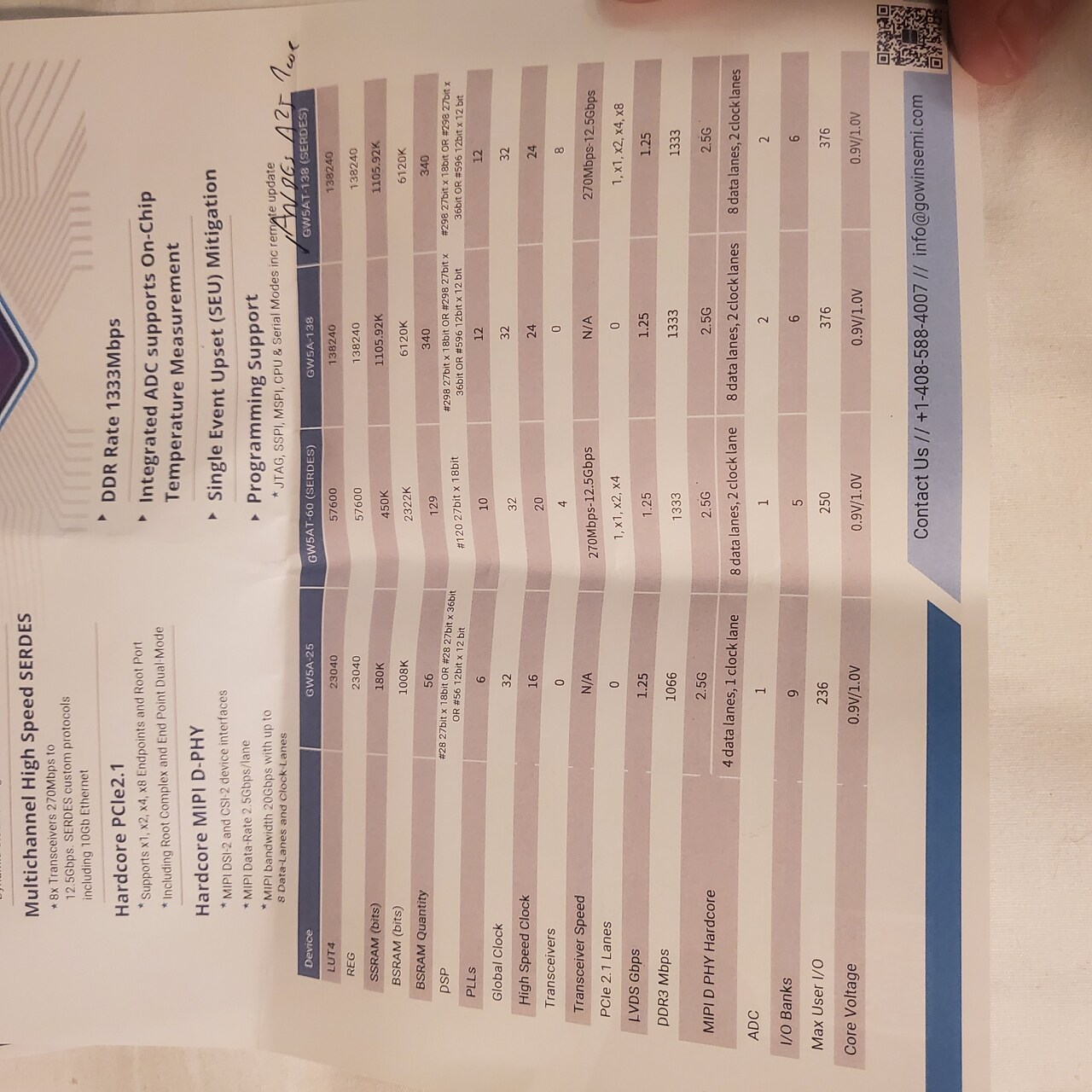 Exklusiv können wir dank CEO Jason Zhu berichten, dass die links gezeigten Modelle G5WA-25 und G5WAT neben dem RISCV-Kern auch einen auf Cortex M4 basierenden Mikrocontroller mitbringen werden
Low-End-Bereich: Renesas mit FPU, Texas Instruments mit „Menschenfreundlichkeit“. Renesas schickt mit dem RA4E2 einen neuen Low-End-Controller ins Rennen, der - das wird vom Standpersonal explizit zugegeben - zur „Bekämpfung“ des STM32C0 vorgesehen ist. Alleinstellungsmerkmal des Cores - mehr Informationen finden
0 1 2 3 4 5 6 7 8 9 A B C D E F WST SECAM 000 AA AA FF FF E7 2E 20 A6 E4 B4 0E 0 7 0 10 0 WST SECAM 010 AA AA FF FF E7 2E 20 A6 E4 B4 0E 0 7 0 10 0 WST PAL B 020 AA AA FF FF 27 2E 20 AB A4 72 10 0 7 0 10 0 WST
V4 p Power Save E - VDD COMS 2 uO n These are the COM output terminals for the indiBoth terminals output the same signal. S output by both master and slave.e not usWhen in master/slave mode, the same signal
USB cables, and a separate specification for low-speed cables exist. VDD USB_VREGO USB_VREGI 1 µF 4.7 µF USB_VBUSEN EFM32 USB Captive Cable USB_VBUS USB_DP 15 R VBUS D- USB_DM 15 R GND USB_DMPU 4k7 Cable shield USB_ID VSS Figure 2.4. USB Low-speed Device Schematics When designing hardware for a Low-speed
Frank E. schrieb im Beitrag #7363869: > Was ist eigentlich an meiner Frage gleich 4 mal "nicht lesenswert" > (18:21)? Threads nicht kapern, neuen Thread dazu anfangen.
Frank E. schrieb im Beitrag #7363869: > Was ist eigentlich an meiner Frage gleich 4 mal "nicht lesenswert" > (18:21)? Weil man von einem Forum Antworten erwartet und nicht noch mehr Fragen?! Weil
will show PB0 going high for a short period of time at each negative edge zero crossing (See Figure 4 and Figure 5). Figure 4. Screenshoot from Oscilloscope, Mains Input and PB0 Output 4 AVR182 2508B–AVR–01/04 AVR182 Figure 5. Screenshot from Oscilloscope, Mains Input and PB0 Output In a real application
