29 31 33 35 37 39 41 43 34 55 (3,30) .360* - 33 35 37 39 41 43 45 47 49 51 53 (9,14) 5 8 68 Position S 0 Recommended Hole Layout 84 Position o 9 Viewed from the Top of Socket c , Tolerance .002 Unless Otherwise Noted e A (0,51) s C .100 o (2,54) s STANDARDCONFIGURATIONS c "
is pulled high by T2. If SW1 is released at this time, T1 is immediately turned off, and 32.768KHZ OS_25M_OUT OSC1 GND 2 GND C22 C7 R6 OS_32K_OUT Package: 3215 2P 25MHZ 0.1uF 10K LEYellow-green light the MCU completes the reset. Due to the effect of C7, T2 will be delayed to turn off. At this time, BOOT0 is still high level, and the MCU will start from the system storage 6pF area, and USB DFU download or serial port ISP download can be performed.
32,768 Hz. The devices are tested not to exceed 35 ppm (parts per million) oscillator frequency error at 25°C, which equates to about ±1.53 minutes per month. With the calibration bits properly set, the accuracy of each M48T58/Y improves to better than +1/–2 ppm at 25°C. The oscillation rate of any crystal
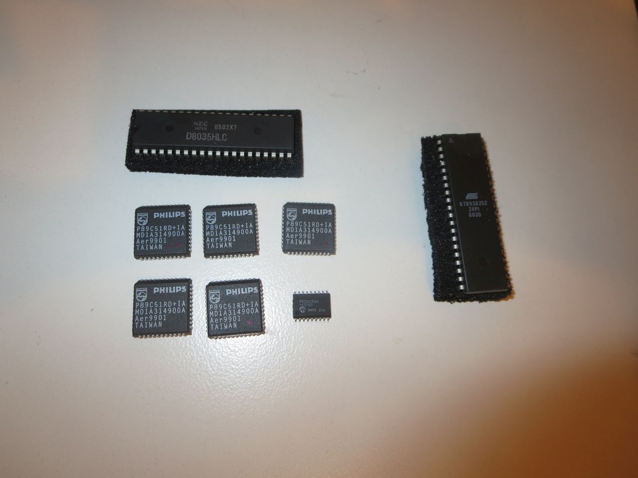
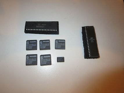
Verschenke die gezeigten älteren Mikrocontroller: 1 St. NEC D8035HLC DIP-40 1 St. Atmel AT89S8252-24PI DIP-40 1 St. PIC16C54A-10/SO SO-Gehäuse 5 St. Philips P89C51RD+IA PLCC-44 Bei Interesse bitte melden. Gruß, Günter
transmitted as a one if the operating voltage has dropped below the low voltage trip point, typically 3.8V at 25°C. This Vsignal is If the supply voltage drops below the low voltage trip transmitted so the receiver can give an indication to the point, the LED output will be toggled at approximately user that
in the graphs on the previous page. where: A, B, C, D, A , B , C and D are constant values Example: at 0 °C, assume X = 5 %, Y = 0.89 % and 1 1 1 1 TCR = 5.08 %/K (see table ), then: depending on the material concerned; see table below. 5 0.89 R
and must only be used when no other devices are connected on the bus. In addition, spikes on the I C-bus lines must be avoided because of the reduced spike suppression. 8.1.4.12 MFRC522 at lower speed modes 2 MFRC522 is fully downward-compatible and can be connected to an F/S mode I C-bus system. The
I’m delivering the package. That’s what I do. I’m a package-delivery guy.” “That’s one way to look at it. Another way is that both you and the package got here at the same time. And that both of you were necessary. I say the package delivered you.” There was a twisted logic to that interpretation, but
in the graphs on the previous page. where: A, B, C, D, A , B , C and D are constant values Example: at 0 °C, assume X = 5 %, Y = 0.89 % and 1 1 1 1 TCR = 5.08 %/K (see table ), then: depending on the material concerned; see table below. 5 0.89 R
. operates at low temperatures (−25°C to −40°C), both the value and ESR of the capacitor will vary considerably. The GRM31CR71C106KAC7 (10 mF, 16 V, X7R, 1206) capacitor manufacturer’s data sheet usually provides
Analog1.8VPower -0.3 1.95 V IOV Input/Output Voltage -0.5 5.5 V TSTG Storage Temperature Range -65 +150 °C T Ambient Temperature 0 +70 °C A LT Lead Temperature - +260 °C (TL, soldering, 10 sec.). 10.2 Operating Conditions Symbol Parameter Min. Typ. Max. Unit Conditions DVDD33 Digital3.3VPower 3.135 - 3.465 V - DVDD18 Digital1.8VPower 1.71 - 1.89 V - AVDD33 Analog3.3VPower 3.135 - 3.465 V - AVDD18 Analog1.8VPower 1.71 - 1.89 V - PD 100BASE-TX - 107 - mA 1.8V only (Power - 54 - mA 3.3V only Dissipation) 10BASE-TX - 57 - mA TX idle, 1.8V only -
. At high case temperatures, thermal limitations will reduce Safe operating area curves indicate C – VCE limits of the the power that can be handled to values less than the limita- transistor that must be
vary depending on operating environment and formatting. † Seagate does not recommend operating at sustained case temperatures above 60°C. Operating at higher temperatures will reduce useful life of the product. 2.1 Formatted Capacity Model Formatted Capacity (1) Guaranteed Sectors Bytes per Sector
15: Environmental characteristics Capabilities Description Atmospherics Temperature Operating –10_ C to +50_ C, Class 5 Nonoperating(storage) –51_ C to +71_ C. Class 3 Humidity To 95% relative humidity at or below +55_ C Altitude Operating To 15,000 feet (4572 meters) Maximum operating temperature to
Hi! Benötigt wird DIL40. Ich hätte sonst auch AT89S... als DIL da. Roger P. schrieb im Beitrag #7981985: > Will die wegwerfen.... Ach so. :o) Versuch es doch hier im Markt! Gruß Jobst
Videotextdecoder ist. Das wird aber spätestens beim verifizieren auffliegen. Ich teste hier mit AT89S52. Gruß Jobst
Testing and measurement techniques. Section 13: Harmonics, interharmonic including mains signalling at A. C. Power port, Immunity tests. r630005d - 16.10.aa – Dieter Helmich Seite 83 von 122 5.9 Checking the level of supplied power If the user wishes to reactivate the booster, this can be done. The booster
event pending flag, set by H/W at INT2 pin’s falling INT2IF 0C.2 R - edge W 0 write 0: clear this flag; write 1: no action R - INT1 (PA1) interrupt event pending flag, set by H/W at INT1 pin’s INT1IF 0C.1 falling/rising edge W 0 write 0: clear this flag; write 1: no action INT0 (PA3) interrupt event pending flag, set by H/W at INT0 pin’s INT0IF 0C.0 R - falling/rising edge W 0 write 0: clear this flag; write 1: no action INTIE1 (0Dh) Function related to: Interrupt Enable All port pin change wakeup interrupt enable PCIE 0D.6
event pending flag, set by H/W while WKT time out WKTIF 0C.3 W 0 write 0: clear this flag; write 1: no action R - INT2 (PA7 or PB5) interrupt event pending flag, set by H/W at INT2 INT2IF 0C.2 pin’s falling edge W 0 write 0: clear this flag; write 1: no action INT1 (PA1 or PB1) interrupt event pending flag, set by H/W at INT1 INT1IF 0C.1 R - pin’s falling/rising edge W 0 write 0: clear this flag; write 1: no action R - INT0 (PA3 or PB2) interrupt event pending flag, set by H/W at INT0 INT0IF 0C.0 pin’s falling/rising
Parameters Sym Min Typ Max Units Conditions Temperature Ranges Operating Junction Temperature T -40 — +125 °C Steady State J Range Storage Temperature Range TA -65 — +150 °C Maximum Junction Temperature TJ — — +150 °C Transient Package Thermal Resistances Thermal Resistance, 5L-TSOT23 JA — 192 — °C/W EIA/JESD51
enters 2·C 1∆t·V (c = 0)+I (c = 0) at position 1 of the right-hand side vector. Note thct I (t = 0) is zero because the voltage V1is applied at t = 0. Finally, the complete matrix equation writes as follows.
impedance change on the Smith chart when adding the notch filter component C 1 L1 L2and C2 PA output impedance Measure the output power at this point and keep this value. Measure the H2 rejection and try to fine tune the notch filter as explained below. Note: Due to parasitic
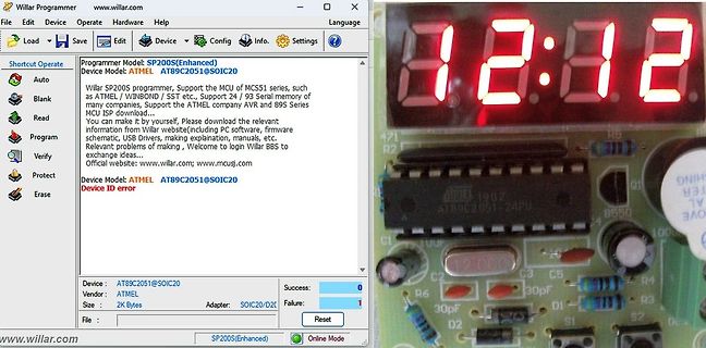
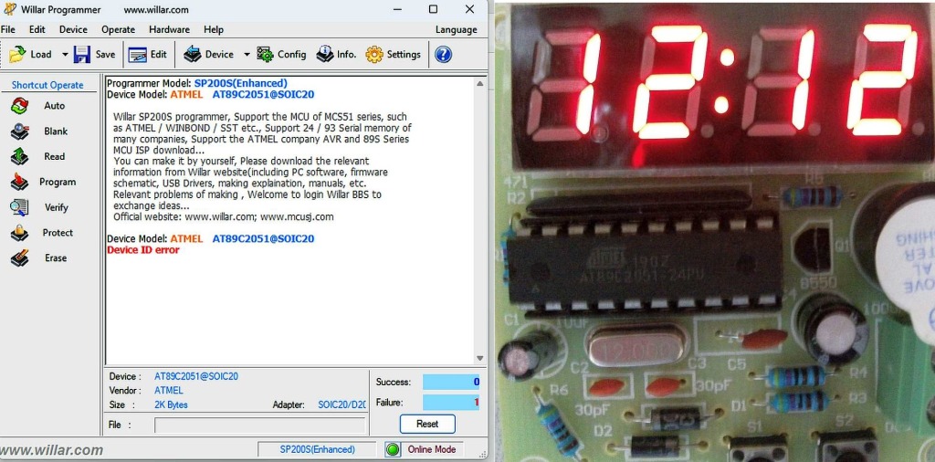
Config Info. Settings Load Save Edit Config Info. Device Model: SP200S(Enhanced) Device Model: ATMEL AT89C2051@SOIC20 Willar SP2005 programmer, Support the MCU of MCS51 series, such as ATMEL / WINBOND - SST etc., Support 24 / 93 Serial memory of many companies, Support the ATMEL company AVR and 89S Series
THERMISTOR RESISTANCE VALUES Tc Resistance Value [kW] Tc Resistance Value [kW] Tc Resistance Value [kW] [5C] Min Typ Max [5C] Min Typ Max [5C] Min Typ Max −40 4130.00 4251.00 4612.34 16 152.51 154.60 156.96 72 13.69 14.10 14.52 −39 3851.00 3962.00 4290.13 17 145.20 147.20 149.28 73 13.19 13.60 14.00 −38 18
we need to send the serial 13 Flyron Technology Co., Ltd. www.flyrontech.com command 7E FF 06 14 00 C7 CF FD 51 EF. 0xC7 and 0xCF are parameter, and the combined data is 0xC7CF, and totally 16 bytes. The high 4 bytes represent the folder name; C here means the folder “12”. The low 12 bytes represent
9 11 21 41 51 91 11 D E E E E E E E E . 3 5 / 9 1 / 1 11 11 11 11 11 11 AUP SEL ECTOR / 8 1 0 C / 2 C C. C. C. C. C. C. BLM15PD300SN1D T K K K K K K K 2 C C 0 1 2 0 0 0 0 0 0 L30 H /OE S OUT 1 1 1 1 1 1 1 3 2 1 5
polynomial of H(s). The result is _ -(RC+ L/R)-:k. [(RC+ L/R)- 8LC]1/2 P1.2 -- - - - - - - - 2 - L - C - - - - - - - (2.4-6) If we allow the source and load resistances to be equal at I n and assign values of L = v'2 henry (H) and C = v'2 farad (F), the poles occur at p= (l -:kj.l)/v'2. We will examine
frmMain.lbAdrFax=F&ax frmMain.lbAdrINet=&Internet Link frmMain.lbAdrMail=&E-Mail frmMain.lbAdrKundNr=C&ustomer No. frmMain.lbAdrUsId=&VAT ID frmMain.spInternetHint=Open Web Browser frmMain.lbAdrLand=C&ountry frmMain.spANewHint=New Entry frmMain.spACopyHint=Copy Data frmMain.spASaveHint=Save Data frmMain.spAAbortHint
characters CPT8 = CPT8 + 1 number characters charactererror un e3 characters sil nce YES error on at least NO 1 frame character YES length NO < 3 bytes YES NO CRC incorrect C P T 2 = C P T 2 + 1 C P T1 = C P T 1 + 1 YES NO slave number = 0 or YES slave NO slave number = my slave CPnumber 04 + 1 number
SCD4x in the operation mode later used for normal sensor operation (e.g. periodic measurement) for at least 3 minutes (single-shot mode: for > 3 single-shots at 1-minute measurement interval) in an environment with homogenous and constant CO c2ncentration. The sensor must be operated at the voltage desired
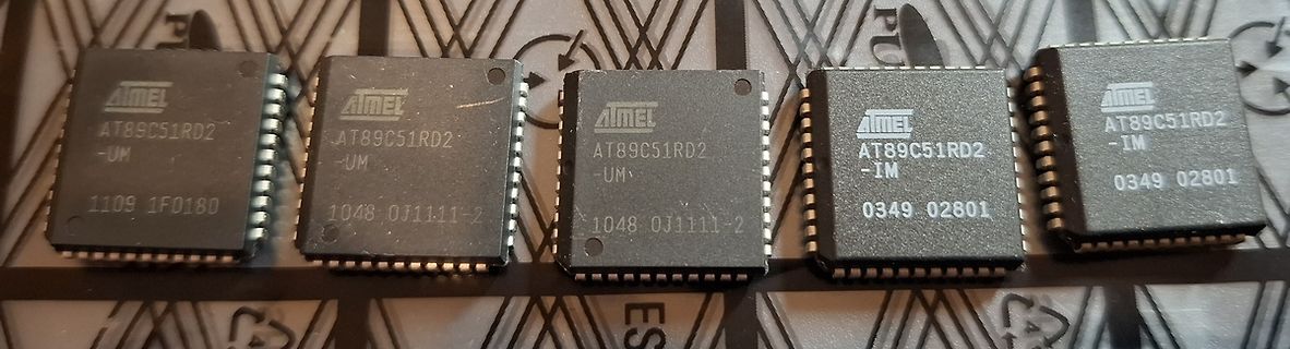
Eckhard T. schrieb im Beitrag #7935422: > Handelt es sich um einen AT89C52 oder eine der AT89C52R.. Versionen? > Letztere lassen sich ggf. leicht seriell programmieren und auslesen. Du meinst wohl eher den AT89S52. Einen AT89C52R* gibt es nicht. Und der AT89C51RC
Peter D. schrieb im Beitrag #7935448: > Eckhard T. schrieb: >> Handelt es sich um einen AT89C52 oder eine der AT89C52R.. Versionen? >> Letztere lassen sich ggf. leicht seriell programmieren und auslesen. > > Du meinst wohl eher den AT89S52. > Einen AT89C52R* gibt es nicht. Und der AT89C51RC
2N2907 gibt es noch medium Power SMD varianten, die bis KW absolut ausreichend sind: PXT2907 (SOT89) https://www.nexperia.com/product/PXT2907A PZT2907A (SOT223) https://www.onsemi.com/download/data-sheet/pdf/pzt2907at1-d.pdf
Kennt jemand den Grund, warum bei PNP Transistoren die "Storage Time" besser ist? PZT2222AT1: 225ns PZT2907AT1: 80ns

 Bild
Bild
 Bild
Bild
 Bild
Bild