applied to VLCD pin must be lower than VDD. Adjust VR to fit LCD display, at VDD=5V, VLCD=4V, VR=15k±20%. Adjust R (external pull-high resistance) to fit user’s time base clock. Note2: Initialization process required to add "NORMAL" command in order to avoid program into non-normal operating mode. 13 Rev 1.2 Package Dimension QFP64 24.7±0.4 3.35MAX 20.0±0.2 0.05MIN 51 33 52 32 2 4 8 0 6 0 7 E 3 0 0 F 0 2 4 4 1PIN INDEX 20 64 1 19 1.0TYP 0.4±0.1 0.15±0.05 φ0.20 M 0-10° 0.1 18.0REF 1.2±0.2 22.3±0.4 Unit:mm 14 Rev 1.2 LQFP64 C D 48 33 H G I 49 3 F A
Continuous Body Diode Current S 75 A Diode Forward Voltage VSD V GSV, I S20A 1.3 V Reverse Recovery Time t 56 ns rr I =20A,di/dt=100A/μs S Reverse Recovery Charge Q rr 45 nC Dynamic Characteristics Input Capacitance Ciss 2028 Output Capacitance Coss V DS0V,V =GS,f=1MHz 756 pF
Levels Main Mix, Ctrl Room Gain Range: Ü to +10dB 1/4” Inputs Stereo Aux Return Level: +4dBu nominal, +20dBumaximum RCA Inputs Tape In Level: -10dBV nominal, +5dBV maximum 1/4” Outputs Main Mix, Ctrl Room, Ext Aux Send Level: +4dBu nominal, +20dBu maximum Headphone Output: 75 ohm output impedance >105mW
with Base series bases. To prevent damage to the device, do not stack Core2 v1.3 with any Base series expansion base. • When stacking Core2 v1.3 with M5 modules, you will need to remove the battery bottom
Protokolle: [c] ISO 14443A, ISO 14443B, FeliCa™, and ISO 15693 protocols [/c] ### Atomic Audio-3.5 Base Wer Sprachinformationen ein- oder ausgeben muss und dafür ein Audio-Frontend benötigt, wird von M5Stack mit der in der Abbildung gezeigten Atomic Audio-3.5 Base bedient.  Cx ± 20% Cv ± 20% bornescommedécritdansletableausuivant. 1,0 mH 0,22 µF 0,00 47µF POINTS DE MESURE INDICATION DE L’OHMMETRE Entre
range, whereas this one has a peak power output of 100 mW nominal and a to- tal power usage of about 20 W (at 12 V) in operation. Pulse radars measure the time of ight of a re ected electromagnetic signal. In contrast, FMCW radars send out signals of linearly increasing frequency and compare the fre- quency
============================== INPUT variable Reads a value from the keyboard. Example: 10 INPUT A 20 PRINT A ---------------------------------------------------------------------------------------------- PRINT (?) expression Displays text or numeric values. Example: 10 PRINT "HELLO WORLD" 20 PRINT A
Du hier https://www.bremerfunkfreunde.de/index.php/sdr/sdr-software oder hier https://afu-base.de/sdrsharp/ mfg
> können. > > Danke für Antworten > > VG Fritz Vorgestellt wirds hier: https://afu-base.de/sdr/ es kann den RTL-Stick Die Relase-Seite ist hier: https://github.com/AlexandreRouma/SDRPlusPlus/releases mfg
Hi Ich habe eine WD Blue WD20SPZX (2,5" 2TB) vollständig mit NTFS formatiert. Dann wollte ich sie mit h2testw testen. Zuerst sagte h2testw ganz normal "es werden nur 1907566 von 1907728 MB getestet". Am Ende des Schreibzyklus
Peter N. schrieb im Beitrag #8064822: > Ich habe eine WD Blue WD20SPZX (2,5" 2TB) vollständig mit NTFS > formatiert. Nimm FAT32
bis 2A > Ausgangsstrom liefert. Das sollten bessere Audio-Verstärker noch schaffen. Da die bis 20 kHz phasenlinear sein müssen, gehen sie oft bis deutlich über 100 kHz.
Vor gut 20 Jahren haben zwei Kollegen einen Demonstrator zur Reichweiten-Verlängerung aufgebaut und den Kunden vorgeführt. Hintergedanke war, unser System zu verkaufen, welches durch Laufzeitmessung und korrelation
Wenn die 20 mA stimmen, und ich die 3V in 500ns aus dem Eröffnungsbeitrag damit verrechne, komme ich auf 500 ns * 20 mA / 3V = 3,3 pF Stimmt doch so, oder? Ein Tasktkopf hat allerdings um 30 pF. Lag es doch
Nemopuk schrieb im Beitrag #8064533: > 500 ns * 20 mA / 3V = 3,3 pF Drei Größenordnungen daneben…
C wave soldering for maximum 5 seconds 260 °C PART NUMBER KEY TS11 - 674 - XX - BK - XXX - RA - D Base Number Actuator Height: Push Force: 43 = 4.3 mm 85 = 8.5 mm 100 = 100 gf 50 = 5.0 mm 95 = 9.5 mm 160 = 160 gf 55 = 5.5 mm 105 = 10.5 mm 260 = 260 gf 65 = 6.5 mm 120 = 12.0 mm 73 = 7.3 mm 135 = 13.5
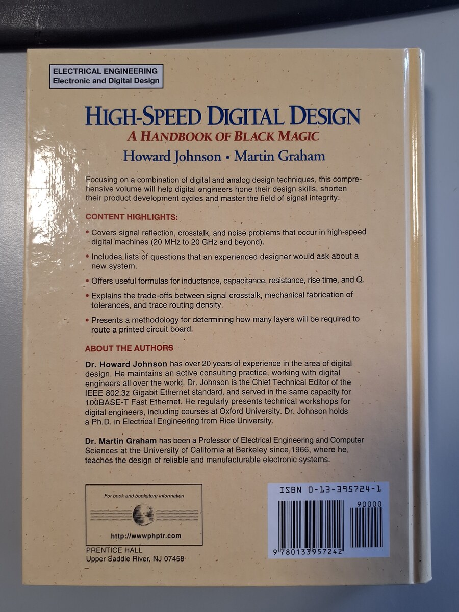
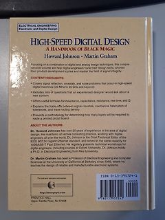
Covers signal reflection, crosstalk, and noise problems that occur in high-speed digital machines (20 MHz to 20 GHz and beyond).
Includes lists of questions that an experienced designer would ask about a new system.
Offers useful formulas for inductance, capacitance, resistance, rise time, and Q.
Explains
direct from CVBS signal; n-channel MOS; Generating of the line synchronous 5-MHz clock for the time base and data clock by means of PLL operation; Very few external components necessary; Adaptative data separation; Frame signal recognition; Decoder for line 16 Bi-phase and start code checking; I<SUP>2<
Collector Capacitance (Cc): *500 pF* (und viele parallel) Forward Current Transfer Ratio (hFE), MIN: 20 In höchster Not könnte man an der Gegenkopplung vorsichtig experimentieren?
weiterzukommen. Nochmal zur Sicherheit: stimmen alle DC Punkte mit dem guten Kanal überein? +/-20% würde ich als "ok" werten. Ich würde tatsächlich ALLE Stufen der Schaltung durchgehen und vergleichen. Spannungen an Basen, Emittern und Kollektoren. Spannungsabfälle über den relevanten Widerständen
IEEE 802.3 for 10BaseT IEEE 802.3u for 100BaseT(X) and 100BaseFX IEEE 802.3x for flow control Optical Fiber 100BaseFX Multi-Mode Fiber Cable Type OM1 OM2 OM3 OM4 Typical Distance 4 km 4 km 4 km 4 km TX Range 1260 to 1360 (nm) Wavelength RX Range 1100 to 1600 (nm) TX Range -10 to -20 (dBm) RX Range (dBm) -3 to -32 Optical Power Link Budget (dB) 12 Dispersion 3 3 3 3 Penalty (dB) 100BaseFX Multi-Mode Single-Mode 50/125 µm Fiber Cable Type G.652 800 MHz x km Typical Distance 5 km 40
against cyberthreats Specifications WLAN Interface WLAN Standards 2.4 GHz: 802.11n with 64 QAM support, 20/40 MHz 5 GHz: 802.11n with 64 QAM support,20/40 MHz WMM for QoS Frequency Band for US (20 MHz operating channels) AWK-3131A-US models only 2.412 to 2.462 GHz (11 channels) 5.180 to 5.240 GHz (4 channels
2 km Standards IEEE 802.3 for 10BaseT IEEE 802.3u for 100BaseT(X) and 100BaseFX IEEE 802.1X for authentication IEEE 802.1D-2004 for Spanning Tree Protocol IEEE 802.1w for Rapid Spanning Tree Protocol IEEE 802.1s for Multiple Spanning Tree
Simplified Chinese 1 x quick installation guide 1 x warranty card Dimensions Ordering Information 100BaseFX 100BaseFX 100BaseFX Total No. of 10/100BaseT(X) Ports Ports Ports Model Name Layer Ports Operating Temp. Ports RJ45 Connector Multi-Mode SC Multi-Mode ST Single-Mode SC Connector Connector Connector
against cyberthreats Specifications WLAN Interface WLAN Standards 2.4 GHz: 802.11n with 64 QAM support, 20/40 MHz 5 GHz: 802.11n with 64 QAM support,20/40 MHz WMM for QoS Frequency Band for US (20 MHz operating channels) AWK-1137C-US models only: 2.412 to 2.462 GHz (11 channels) 5.180 to 5.240 GHz (4 channels
Auktionshandel werden auch Alternativen angeboten, teils recht schick im Plexiglasgehäuse für ca. 20 Euro. Angeboten z. B. als "USB 2.0 Full Speed low cost Programmer für ATMEGA Chips" oder "AVR USB ISP Programmer ATMEL ATMEGA STK500". Die Adapter funktionieren auch mit BasCom (aber auch mit AVR Studio
Sie sind per USB an den PC angeschlossen und arbeiten über einen virtuellen COM-Port. Achtung: In BasCom funktioniert das nur bis COM9. Wenn sich das Gerät z. B. auf COM15 installiert, wird es im BasCom evtl. nicht gefunden. Dann in der Systemsteuerung entsprechend umstellen. USBisp. AVR Programmierdongle
Page 116 of 174 GPS - Compendium Reference Station: in the SBAS area there are several reference base stations, which are networked to each other. The base stations receive the GNSS signals. They are exactly surveyed with regard to their position. Each base station determines the deviation between the
PS: Die Spannung über R3 ist genauso groß wie über R1. Weil die Basen verbunden sind.. Sollte schon mindestens 1V sein. (>0,7V) Sonst wird es instabil. Jens M. schrieb im Beitrag #8058987: > - Linearregler, Lowside Ja, OK ist highside. Kann man auf lowside
Warum nicht so? R2 besteht aus 20R + Poti 50R. V2 simuliert das "Digitale Enable". Da ich in LTspice auf die Schnelle keine IRLeds finden konnte, habe ich mit roten LEDs simuliert, mußte aber wegen der höheren LED-Spannung die Versorgungsspannung
extension called Walk-By/Drive-By Reading will enable LoRaWAN devices to efficiently connect to mobile base stations that might be mounted on vehicles, flown on drones, or carried by hand. This extension will be especially valuable in cases where devices fall outside the coverage of fixed network infrastructure
287175605441 ### OLIMEX: ESP32-P4 als langsamer Access Point OLIMEX bietet mit dem um rund € 20 erhältlichen ESP32-POE-ISO eine ESP 32-P4-Platine an, die dank ihrer Power Over Ethernet-Fähigkeit am Router parasitieren kann. Nun zeigt man eine Software, die diese Platine in einen Behelfsrouter
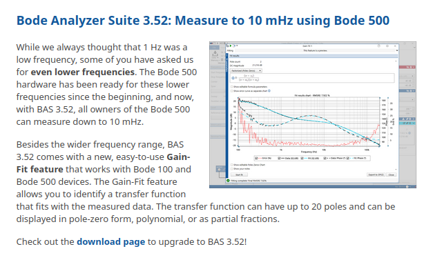
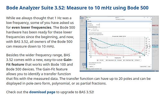
The Bode 500 hardware has been ready for these lower frequencies since the beginning, and now, with BAS 3.52, all owners of the Bode 500 can measure down to 10 mHz.
Besides the wider frequency range, BAS 3.52 comes with a new, easy-to-use Gain-Fit feature that works with Bode 100 and Bode 500 devices.
Ratings Value Unit VCEO Collector-Emitter Voltage 45 V VEBO Collector-Emitter Voltage 45 V VCBO Emitter-Base Voltage 7 V VCEX Collector-Emitter Voltage VBE-1.5 V 50 V C Collector Current 15 A B Base Current 7 A PT Power Dissipation @ T C 25° 117 Watts TJ Junction Temperature -65 to +200 °C TS Storage Temperature
60 u R C l u 0.6 p ÎÎÎÎÎÎÎ t i 40 VI(AV)– O = 25 V u R ÎÎÎÎÎÎV = 10 V O 0.4 I(PP) ÎÎÎÎÎÎÎ= 100 mA 20 f = 120 Hz 0.2 ÎÎÎÎÎC = 0 o ÎÎÎÎÎÎÎ= 25⋅C 0 0 0 10 20 30 40 50 60 70 80 90 100 0 10 20 30 40 Time – ms VO – Output Voltage – V Figure 3 Figure 4 POST OFFICE BOX 6553DALLAS, TEXAS 75265 5 TL783 HIGH-VOLTAGE
..................................................................................................–20V to +60V Enable Input Voltage (V ) ........................................................................................................................... –0.3V to V EN IN Power Dissipation......
LES VERIFICATIONS 3D. R1 L L RED Débrancher les fils des bornes du filtre Cx R2 Cy R2: 680 K Ohm ± 20% antiparasite. F8A A l’aide d’un ohmmètre, vérifier entre les L(min) Cx ± 20% Cv ± 20% bornescommedécritdansletableausuivant. 1,0 mH 0,22 µF 0,00 47µF POINTS DE MESURE INDICATION DE L’OHMMETRE Entre
disappearance issue. 7. Resolved the issue where statisitcs is performed only once under 50 ms time base. 8. Resolved the issue where system crash occured when modifying the source of All Measure under zoomed time base in measurement settings. 9. Resolved the issue of invalid setting of screen grid. 10
released images based on Ubuntu 26.04 LTS, codenamed Resolute Raccoon the latest long-term support base. As always, Armbian applies its own platform-optimized kernel, board-specific patches, and tested drivers on top so what you get is a clean, stable foundation across SBCs, PCs, and cloud environments
Fisch Stäbchen mit 100% Seelachsfilet Batonnet de poisson à base de filet de lieu noir ALNA. FISCHSTAEBCHEN 250G 4.49 1 kg = 17.96 4104420217188 W20 R1524 1SH B10 A EDEKA 4093601001 Goldknusper Filet 3 STÜCK NUTRI-SCORE ABCDE asc
loskriegen und wenn ja, wie lang der vorher im Lager steht. 400 Euro für das Ding, da seit mindestens 20 Jahren komplett veraltet ist? Wer kauft sowas und warum? Außer für einen bestehenen Test- und Prüfaufbau, den man nicht ändern kann oder will, braucht das keiner.
P.S.: Man kann die Zeitbasis sowohl im passenden Feld im "Config"-Menü eintippen, oder im "Time Base"-Menü. Im "Config"-Menü sieht man allerdings nichts mehr von den Signalen. Mit den Tasten rechts von den Ziffern kann man einen Exponenten anhängen. Z.B. ns. Passt die Eingabe nicht ins 1-2-5-Raster
Whisper gibts auch in schnell: https://github.com/ggml-org/whisper.cpp Mit Vulkan auf der 9070 ca 20x Realtime mit dem base.en Model Mit large-v3 3.3x Realtime Mit large-v3-turbo 14x realtime Nochmal Gemma. Diesmal mit mmproj-F32 ... macht irgendwie auch keinen Qualitätsunterschied. Wahrscheinlich
jedenfalls keine KI-Neuheit. Diktiersoftware für den PC war schon in Windows Vista, also vor ca. 20 Jahren integriert, nur wussten das die meisten PC-Nutzer gar nicht. Und schon vor circa 30 Jahren konnte man "Dragon Natural Speaking" für Windows kaufen. Manche Übersetzer haben das schon damals

 Bild
Bild
 Bild
Bild
 Bild
Bild
 Bild
Bild
 Bild
Bild
 Bild
Bild