selbstverständlicher Standard. Heute dann aber eher so: https://www.otto.de/p/hanseatic-kopffreihaube-sy-103e9g-p1-c120-l52-600-sy-103e9g-p1-c120-l52-600-inkl-3-jahre-herstellergarantie-523227611 Ich habe gar keine, ist aber auch nicht ideal - nur Lüften ist auch nichts. Ich denke ich persönoich würde es
Oder es wird nur ein Ring entlang der Wände abgehängt: https://spanndo.de/resources/files/b288362f5e02be36619a55fe9f5b22c6.jpg Bei Einbau einer ernstgemeinten Dunstabzugshaube und Vorhandensein eines Durchbruchs/Kernbohrung an anderer Stelle kann die letztgenannte Lösung bei ausreichender Raumhöhe
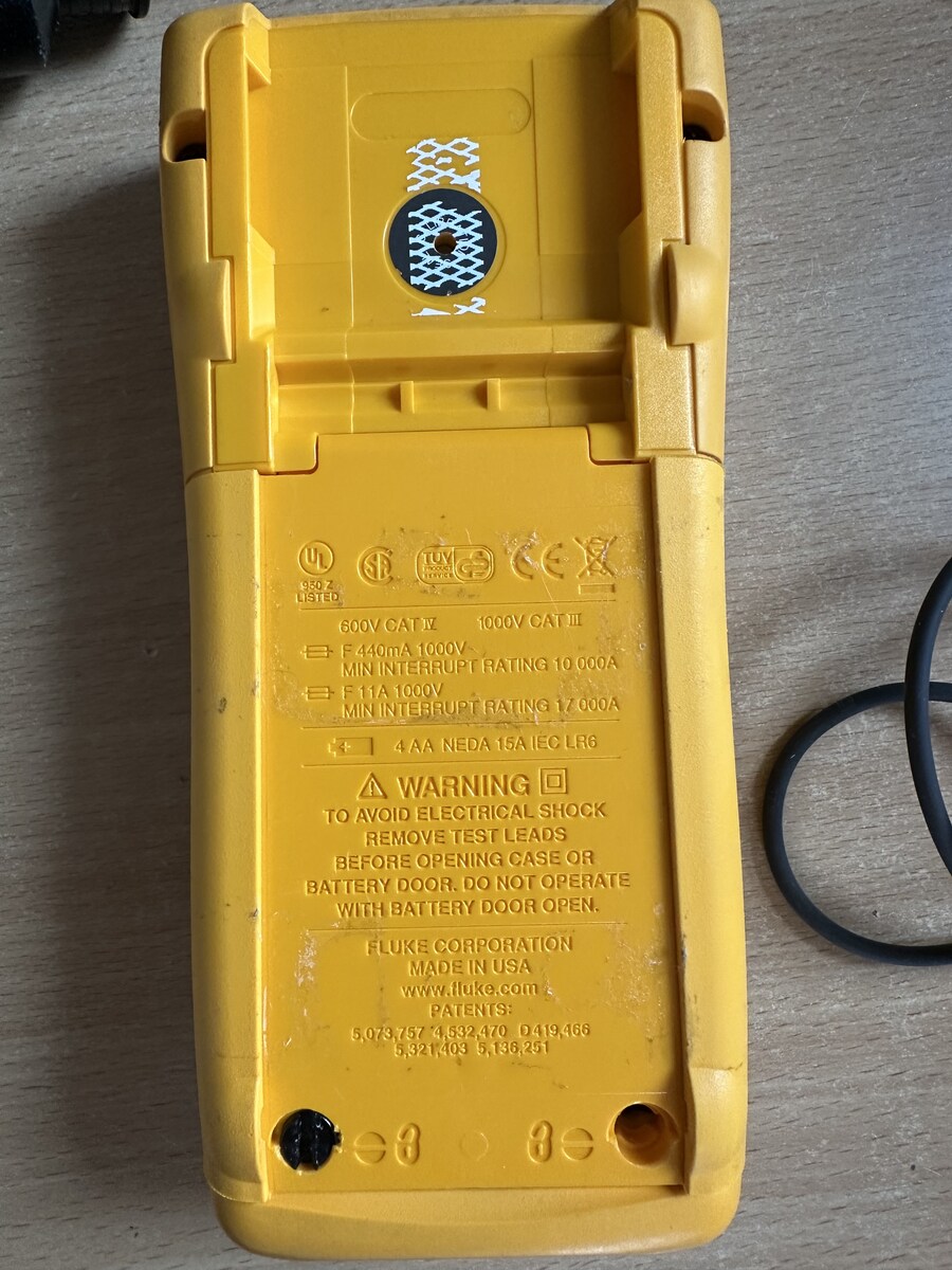
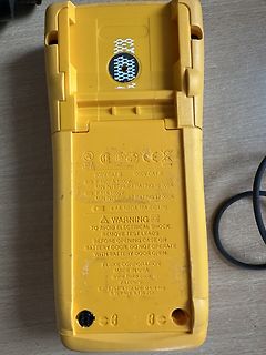
600V CAT III 1000V CAT III
F 440mA 1000V MIN INTERRUPT RATING 10 000A
F 11A 1000V MIN INTERRUPT RATING 17 000A
4 AA NEDA 15A IEC LR6
A WARNING
TO AVOID ELECTRICAL SHOCK
REMOVE TEST LEADS
BEFORE OPENING CASE OR
BATTERY DOOR. DO NOT
1.27 d e p –1 c I 10 e 1.26 t e p e u 10–2 R 1.25 O – – e o Vr 1.24 Z –3 10 1.23 10–4 1.22 101 102 103 104 105 106 107 –75 –50 –25 0 25 50 75 100 125 150 175 f – Frequency – kHz TJ– Virtual Junction Temperature – ⋅C Figure 7 Figure 8 †Data at high and low temperatures are applicable only within the recommended
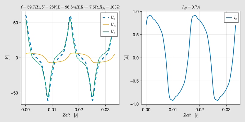
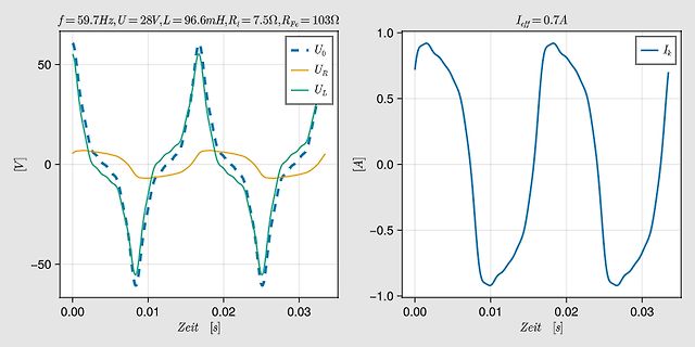
aus L, Ri, Rfe und setze davor eine Quelle, die den Spannungsfaktor (kU) mit der Kreisfrequenz (2*pi*f_dynamo) multiplizieren kann. Das Produkt wird dann mit dem Sinus der (Kreisfrequenz*Zeit), also pi*f-, 2pi*f-, 3pi*f *t multipliziert, durch die Schaltung gejagt und auf der x-Achse (Zeit) abgerollt
hoch. Es scheint zu funktionieren. Kleine Korrektur meines ersten Posts: Das hier : "also pi*f-, 2pi*f-, 3pi*f *t" ist falsch. Es muss immer 2pi heißen und f wird größer. Hannes J. schrieb im Beitrag #8050651: > vermutlich ist AC-Analyse eher das was du suchst. Ja, aber da geht das mit
- 1D RLCDSA036DRE0 U Affichage à cristaux liquides 1 AP 3- 1E LHLD-A002URF1 U Support DEL 1 AC 3- 1F PSHEPA569WRE0 U Feuille DEL 1 AC C1 RC-KZA087DRE0 U Condensateur 0,1 uF 50 V 1 AB C2 RC-EZA323DRE0 U Condensateur 470 uF 50 V 1 AA C3 RC-KZA087DRE0 U Condensateur 0,1 uF 50 V 1 AB C4-5 VCKYD41CY103N
and VIN−) Voltage Range (Note 4) AC Electrical Characteristics The following specifications apply fCC 5 VDC and T MINT AT MAX unless otherwise specified. Symbol Parameter Conditions Min Typ Max Units TC Conversion Time CLK= 640 kHz (Note 6) 103 114 µs TC Conversion Time (Notes 5, 6) 66 73 1/CLK fCLK
107 S. F. Sichla HF-Technik mit dem NE/NA 602/612 beam-Verlag 2006 140 S. F. Sichla Hochfrequenztransistorpraxis beam-Verlag 2008 275 S. F. Sichla Kabel & Co. in der Funktechnik vth 2. Aufl. 2004 115 S. F. Sichla Messpraxis für Empfänger, Sender und Antennen beam-Verlag 2. Aufl. 2022 103 S. F. Sichla Mikrocontroller und USB Franzis Verlag 2010 379 S. F. Sichla Rauschen in der Elektronik und Funkpraxis beam-Verlag 2015 103 S. F. Sichla Schwingkreise und LC-Filter in der Anwendung Funk
Thomas F. schrieb im Beitrag #8045912: > Jetzt bin ich mir unsicher ob es sich überhaupt lohnt nach der > Fehlerursache zu suchen, Wohl kaputt gegangen als Balancer und Ladekabel falsch verbunden wurden
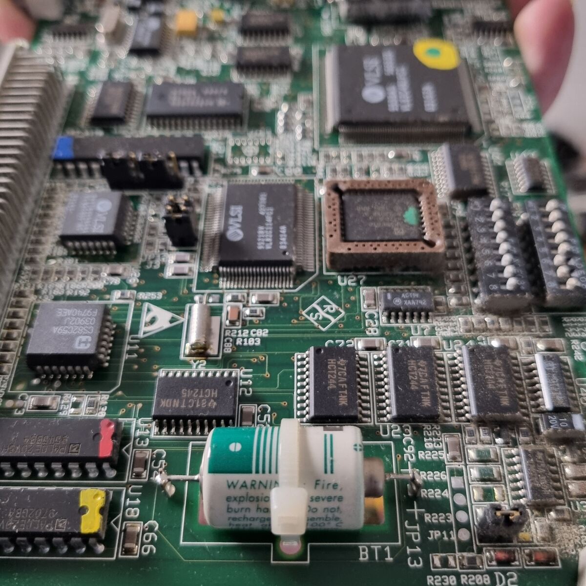
Micro ist ein STM32F103. Gut abgelasert, aber nicht gut genug. Unter dem Display ist noch ein Chip mit abgeschliffenem Marking.
sealed, RT III l RoHS Compliant Please see page 6 for more information n PARTNUMBER INFORMATION FTR-F1 A A 005 V - RG [Example] (a) (b) (c) (d) (e) (f) (a) Relay type FTR-F1 : FTR-F1 Series (b) Contact configuration A : 2 form A (SPST-NO) C : 2 form C (c) Coil type / enclosure A : Standard type (530mW
Heinz-Urs K. schrieb im Beitrag #8040758: > 35V/100yF, Nur so zur Info (da Lothar das Problem schon beschrieben / gelöst hat): Das "µ" wird durch halten der Alt-Gr-Taste und drücken der "m"-Taste ausgegeben.
pins Manufacturer's logo, type designation and date code YYWW stamped on in white (YYWWD for tpye J103) Types J213, J215, J217 and J219 qualification based on AEC-Q200, Rev. D UL approval for all types to UL 1434 (file number E69802) VDE approval for all types (licence number 40040539) IECQ certificate
configuration to the Probe socket using a four-wire test lead. R 7 0 1 +Vp wal * CZ i n 2R02 | pa aoe 101 a | F801 103 In i202.7e e4ai ero a v13 i aad | C37 =Va i pe? S a03 e zoe 1208 0G 1210 viz05AWE2VI206BAw6é2 vI2Z07AWEZ c37Saoe a ss[see ee¢seos C U R R S O U R C E 8 6 0 4 2 9 Figure 3.7 Current source 3 -
be measured ispassed to thed.c.attenuatorwhere by means of resistors switched by attenuated 11-11 oF 1111.11 times, The table indicates the attenuation factor for each range, the A D C input The 11.14 attenuation isachieved with the resistors 1102, R103 and the Ri of the ADC, The 1111.11 1 1 0 8 and
when switching TTYs * Bug fix - greeter crash when switching TTYs * Raspberry Pi firmware dce3a7f35498e1a6340748f599e7d74d9001c1fe * Linux kernel 6.12.75 - 89050b1059997d38d55462b323b099a6436dc10d --- via https://downloads.raspberrypi.com/raspios_armhf/release_notes.txt [/c] ### Altera
strings as per PEP 750 https://peps.python.org/pep-0750/. Template strings (or t-strings) are similar to f-strings, allowing expressions within the string literal. But unlike f-strings, t-strings do not concatenate the pieces of the literal, rather they remain as separate components within a Template object
8to R11: 300 kΩ C 1 C 2 C3 C 4 C 6 C 8 R12: 150 kΩ R14: 430 kΩ R17: 51 Ω C14 C5 C 7 C9 C1, C2: 4700 pF C 3to C11: 0.01 µF R1 C12 C 13 C10 C 1, C13: 1000 pF C14: 2200 pF C11 SHV-R SIGNAL OUTPUT : BNC-R * The dashed line portions at SHV-R and BNC-R indicate an internal shield (ground). THBV4_0530EA Figure
constant large enough, the CP+ 1 (26) Base/Emitter junction of the top transistor can be forward 4 * p * F * LP biased and a short circuit may be generated through Q1/Q2. C + 1 + 4.39 nF This instantaneous power can be much higher than the P 4 * p * 60000 * 1.6 * 103 transistors can sustain (the FBSOA characteristic
**Determine the Scope:** * To make the code usable, I need to specify a common board (like Nucleo-F103 or similar) or keep it generic enough but with pin definitions. * I need to include the necessary header files. * I need to show the `main.c`, `main.h`, `stm32fxx_hal_conf.h` (or similar), and `system_stm32xx.c
1x32x2.54mm_Straight sein. Das ist eine 2-reihige. Ich habe genau diese: Link:https://www.ept.de/index.php?103-40034_de
F. schrieb im Beitrag #8032968: > Allerdings scheinst du ja relativ wenig Ahnung zu haben, wie man das > Programm überhaupt benutzt So möchte ich das nicht sehen. Das ich kein KiCad-Guru bin, und
len ESC D L ESC G D 0 0 127 63 bcc > { SendByte(buf[i]); $11 $0A $1B $44 $4C $1B $47 $44 $00 $00 $7F $3F $2A bcc = bcc + buf[i]; } < <ACK> SendByte(bcc); // Send checksum $06 } Example fo a complete datapackage C-example to send a datapcket Request for content of send buffer <DC2> 1 S bcc > The command
107 S. F. Sichla HF-Technik mit dem NE/NA 602/612 beam-Verlag 2006 140 S. F. Sichla Hochfrequenztransistorpraxis beam-Verlag 2008 275 S. 6 F. Sichla Kabel & Co. in der Funktechnik vth 2. Aufl. 2004 115 S. F. Sichla Messpraxis für Empfänger, Sender und Antennen beam-Verlag 2. Aufl. 2022 103 S. F. Sichla Mikrocontroller und USB Franzis Verlag 2010 379 S. F. Sichla Rauschen in der Elektronik und Funkpraxis beam-Verlag 2015 103 S. F. Sichla Schwingkreise und LC-Filter in der Anwendung Funk
Hier ist der originale funktionierende Dump. https://www.dropbox.com/scl/fi/amqb98qtde4ve7ggou103/Netgear_WAX214v2_F59L1G81MB-TSOP48.BIN?rlkey=l55j9eprz83b5hqx9y7tw1c3o&st=3cfedolh&dl=0
3.5 VDC 6.2. Oven not at temperature a. Voltage < +1 VDC 7. ENVIRONMENTAL 7.1. Humidity MIL-STD-202F, Method 103B, Test Condition A (95% R.H. @ +40°C, non-condensing, 240 hours) 7.2. Storage temperature -40°C to +85°C 7.3. Vibration (non-operating) MIL-STD-202F method 201A (0.06" Double amplitude, 10 to 55 Hz) 7.4. Shock (non-operating) MIL-STD-202F method 214 test condition J (30 g’s, 11 ms, Half-sine) 8. MECHANICAL 8.1. Applicable series OCXO 134 series 8.2. Model number OCXO 134-10 8.3. Outline drawing 125-396 ISOTEMP RESEARCH INC. CODE ID. PART
66,001f00,-90 +INQ:aa:bb:cc:dd:ee:ff,001f00,-71 …… +INQE Command 22: Cancel inquire—— Distal bluetooth equipment command answer parameter AT+INQC OK none Note: the command only in the Lord shall state model
Schachtel heraus. Mein "Liebling" ist seit ein paar Jahren der STM32L496. Angefangen habe ich mit dem F103 und F407 unter Coocox und Atollic. Obwohl der F103 nach heutigen Maßstäben veraltet ist, war er ziemlich gutmütig und relativ einfach zu verstehen. Allerdings litt er unter diversion Bugs im Silizium
Community und das Wiki... Und ChatGPT... Ich schlage mich gerade schon seit vielen Stunden mit dem F429Disc1 samt LCD und Framebuffer herum. Beispiele funktionieren nicht, schon erwähnt. Aus den Projektstrukturen, die in Eclipse übel gemappt werden durchzublicken, wenn BSP und Device-Treiber im Spiel
Zufällig bin ich da auch gerade drauf gestoßen. In meinem Fall ist es der STM32F103C8T6 (https://www.buerklin.com/de/p/stmicroelectronics/microcontroller/stm32f103c8t6/51S2352/) "Als Privatkunde können Sie diesen Artikel kaufen, sobald wir ihn wieder vorrätig haben." Im Warenkorb

 Bild
Bild
 Bild
Bild
 Bild
Bild
 Bild
Bild
 Bild
Bild
 Bild
Bild
 Bild
Bild
 Bild
Bild
 Bild
Bild