comparator A4. The non-inverting input of A4 receives a Parts list for Resistors: 2 and 4 R3 = 470 k l R4 = 33 k R6 = 270 fl R7 = 2M2 R8 = 1 k Capacitors: Cl ,C2 = 470 n C4.C5 = 2n25 V C7 = 47 p/25 V Semiconductors: IC1 = TL 084 D3 = zener 2V7 Miscellaneous: PI = 47 k preset LI ,L2 =10 mH choke which
1 2 3 4 5 6 7 8 p v h A A + V2 .param rlim=6 .param rs=10 150 .param rgate=33 + V3 150 v h p v h B k B 0 0 Q29 5 0 R 1 7 IXTH24N50L = r={rgate} 0 r={rgate} r={rgate} r={rgate} r={rgate} r 0 Q31 Q33 Q35 Q37 4 N R60 17 R61 7 IXTH24N50L R62 9 IXTH24N50L R66 1 IXTH24N50L R70 3 IXTH24N50L
35 18 x 40 - - - - 8200 - 18 x 40 - - - - - DIMENSIONS in millimeters AND AVAILABLE FORMS Ø D Ø D L L + - F 15 min. 4 1 Ø d 0 Ø d min. F Fig. 2 - Form CA: Long leads Fig. 3 - Form CB: Cut leads Formed leads for Ø D = 8 mm with pitch F = 5 mm Fig. 4 - Form TFA: Taped in box (ammopack) Revision: 11-Oct
noted. Parameter Symbol Min. Typ. Max. Units Conditions e , Output Noise Voltage — 400 — C = 10 µF n L (10 Hz to 100 kHz) — 260 — µVRMS C = 33 µF L = 100 mA L Ground Current in — 2 10 MIC29150/1/2/3 only µA Shutdown — — 30 VEN = 0.4V Reference - MIC29xx2/MIC29xx3 1.228 1.240 1.252 V Reference Voltage
0.015 — A2 3.56 4.06 0.140 0.160 B 0.38 0.51 0.015 0.020 C1 1.52 0.20 0.30 0.060 0.008 0.012 D 41.78 42.04 1.645 1.655 D2 38.10 — — 1.500 — s ) E 15.24 — — 0.600 — c t( — E1 13.59 13.84 0.535 0.545 e1 2.54 — — 0.100 o —d — eA 15.24 — — 0.600P r — — eB 15.24 17.78 te 0.600 0.700 L 3.18 3.43 le 0.125 0.135 S 1.78 2s03o 0.070 0.080 Nα 32 b10° 32 10° - O Figure 11. PDIP32 - 32 lead Plastic DIP, 600 mils width, Package Outline t( s u c o d A2 A P r A1 L α e B1 B e1 eA C le t D2 eB o D b s S O N E1 E 1 PDIP 1. Drawing
Conversion Rate in Free-Running INTR tied to WR with 8770 9708 conv/s Mode CS =0 V DC, CLK=640 kHz tW (W R)L Width of WR Input (Start Pulse Width) CS =0 V DC (Note 7) 100 ns t Access Time (Delay from Falling C =100 pF 135 200 ns ACC L Edge of RD to Output Data Valid) = = t1H,0H TRI-STATE Control (Delay CL 10
Michael B. schrieb: >>> 79xx brauchen halt eine Mindestlast. >> >> Ich habe bei meinen Netzteilen mit 78xx oder 79xx immer am Ausgang >> eine Led mit 5-10 mA als Kontrolle vorgesehen, da gibt es das Problem >> des TO automatisch nicht... > > Ich hatte noch keinen 78xx, der im Leerlauf seine Spannung überschritten > hat. Um 78xx geht es auch nicht.
l o m u s b es e l e c t e d . Signal nane a C a 6 - 1 6 S I G N A TON T H ED A TBUS D 1 7 0|1 S I G N A T U R E S D O pin 39 | UUUU D 2 pin 37 | 8484 D 3 pin 36 | P763 D 5 pin 34 | 0356 D 6 pin 33 | 4759
1-Sv 7aWR ; : L risa EF06 ci9 0¥ WEA i ja G {*}bs ob an 124 . : HEF4Owea YWapis14 SV L w lYenisi7_ con 02Pr fx, x3 s2SWITCHES. 3Tr i HFO6 T’ +/-UP | DOWN AUTO/MAN i -5V ZEROV10 RESET ' Fig. 33. Interruptcontroller ant
s 32. Adjusting the PM2519 with the aid of a controller... 02. . 0 e e e s e e e e e e e eees 3 8 33. P O A i e ee e e e e e e e e eet ee cnet e t t e reee er e s 8 6 34, | 35. AdjustingthebaterypowerSupply... ...eccceeceeeeeveseanerenesasB13 _ 0 5 4. F A U L T - F I N D I N G a t 4a. General o . o
Harry L. schrieb im Beitrag #8037413: > Wolf17 schrieb im Beitrag #8037407: >> Mich interessiert welche Abstimmspannung sich beim preiswerten (10€) >> 10MHz Frequenzstandard mit dem OCXO Modul von CTI OSC5A2B02
einspeisen und dann einen Rp wählen: 3k9 ~1,49...1,97V, 3k3 ~1,45...1,90V, 2k7 ~1,40...1,81V, 2k2 ~1,33...1,70V, 1k8 ~1,26...1,60V.
(real or virtual via a capacitor) in order to eliminate the flickering. The value of the inductor L is a function of the input line frequency (50Hzor60 Hz), together with the characteristics of the lamp. The impedance of L is given by Equation 1: Z = L*ω L (1 with: ω = 2*π*F F = in Herz L = in Henry
vergessen zu erwähnen: - Bisher benutze ich ein AMS1117-3.3 Modul vom Ali. - Neu wollte ich den L78L33 benutzen, weil ich nur 10-20mA benötige. Die Drop-Spannung hatte ich nicht auf dem Schirm. Was ist mit dem Rest der Schaltung und mit meinen Fragen?
> Drop-Spannung hatte ich nicht auf dem Schirm. Der L78L33 geht nicht. Wenn dann eher dein AMS1117, der braucht nur reichlich 1V, erst recht bei einer handvoll mA. Ist aber auch reiner Luxus.
Halbwertszeiten zu hantieren bringt also wenig Erkenntnis. Sag das mal dem Universalgelehrten Harald L., auch bekannt als Larry Hesch! https://www.youtube.com/watch?v=5muCKsehUsI RIP!
Netz stabilisieren (zumindest für 1/2 Stunde): https://www.energy-charts.info/charts/power/chart.htm?l=de&c=DE&source=battery_unit_eex Die Daten sind vom Fraunhofer-institut.
D D N G V G V V G C V V S L A A A A A T A 1 R P S Figure 1. W5500 Pin Layout 1.1 Pin Descriptions Table 1. Pin Type Notation Type Description I Input O Output I/O Input / Output A Analog PWR 3.3V power GND Ground W5500 Datasheet
Loop (PLL) Power Amplifier Control Logic TEST VBAT XT1 XT2 VDDA Power Management UHF Transmitter L e PAOUT TP1 SupplySwitch PowerOnReset A s L w m Test/Debug X O P P A VSSPA Logic TP2 SwitchLogic PortSenseLogic ControlLogic VSSA RISC Controller and Peripherals Watchdog Interrupt Timer System Timer
edge of E signal. Table 6-2: Control pins of 6800 interface Function E R/W# CS# D/C# Write command ↓ L L L Read status ↓ H L L Write data ↓ L L H Read data ↓ H L H Note (1↓ stands for falling edge of signal H stands for HIGH in signal L stands for LOW in signal In order to match the operating frequency
edge of E signal. Table 6-2: Control pins of 6800 interface Function E R/W# CS# D/C# Write command ↓ L L L Read status ↓ H L L Write data ↓ L L H Read data ↓ H L H Note (1↓ stands for falling edge of signal H stands for HIGH in signal L stands for LOW in signal In order to match the operating frequency
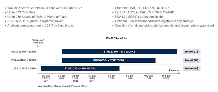
144 MHz Arm® Cortex®-M33 core with FPU and DSP
Up to 593 Kbytes of RAM, 1 Mbyte of Flash
Up to 256 Kbytes of RAM, 1 Mbyte of Flash
2.7–3.6 V, <100 µA/MHz dynamic power
Ambient temperature up to 125°C without impact
Ethernet, USB, I3C, FDCAN, OCTOSPI
Up to 3x ADC, 2x DAC, 2x COMP, OPAMP
PSA L3 / SESIP3 target certification
Optional SCA-resistant hardware crypto with key storage
Coupling & chaining bridge with symmetric and asymmetric crypto accel
STM32C5 portfolio
Flash size/ RAM size
512kB
P / R39 R47 500 R57 500 F 500 1.0k l 1.0k A T39 R40 R41 t R50 R61 R62 R65 P 2.0k 2.0K u 220 2.0k 2.0k 220 Y B R – T43 T44 B l t T60 T61 B–YClamp r 11 B T62 T63 T64 T65 T45 T46 R60 R47 4.7k 4.7k T47 T59 T58 T48 T66 R38 R43 R44 R45 R49 R52
Soweit bin ich jetzt schon: Adresse 78 (Rumgehexe mit der 3C schon erledigt.) Befehle zum Initialisieren der Reihe nach eingegeben: 0x8D, 0x14, 0x20, 0x8D, 0x14, 0xAF Dann zeigt mir das Display schon einmal Rauschen, bzw. kryptische Zeichen
als mehr oder > weniger gelungenes Wortspiel „Dec → Hex“ interpretiert, ... Bestimmt nicht, 0x78 = 0x3C shl 1. Mit dezimal ist da nichts im Spiel.
beryllium copper with [1.32]yp. 8 5 tin or gold plating (see table) .015 .210 Max. ) [.381]yp. [5.33] 0 A 8 : e .128±.007 A [3.25±.178] l .150±.004 .150±.004 c [3.81±.102] [3.81±.102] L C e [0.58±.051]p. i u .048 O .100±.008 [1.22] Sockets with Straight Solder Tails [2.54±.203]yp. 0 2 - 8 5 0 6 : c
PLASTIC PACKAGE E1 IAREA 1 2 3 N/2 INCHES MILLIMETERS SYMBOL MIN MAX MIN MAX NOTES -B- A - 0.210 - 5.33 4 -A- D E A1 0.015 - 0.39 - 4 PLANE A2 0.115 0.195 2.93 4.95 - -C- A2 A SEATING B 0.014 0.022 0.356 0.558 - PLANE L C B1 0.045 0.070 1.15 1.77 8 L D1 A1 eA C 0.008 0.014 0.204 0.355 - D1 B1 e eC C D
energy, single pulse E - - 450 mJ I =30 A, R =25 AS D GS Gate source voltage V GS -20 - 20 V - - - 78 T C25 °C Power dissipation P tot - - 2.8 - T A25 °C, R thJA5 K/W 1) Operating and storage temperature T,jT stg -40 - 150 °C - 2 Thermal characteristics Table 3 Thermal characteristics Values Parameter
expected range. The switching and port selection is, therefore, deterministic [/c] ### CUI P78B-1000 - SIP3-Schaltregler als Ersatz für LM78xx. Wer Linearregler durch Schaltregler ersetzt, erhöht die Effizienz. CUI - wir meinen hier den Teil von CUI, der nun zu BEL gehört - offeriert mit der P78B-Serie eine Familie von im SIP3-Gehäuse vorliegenden Schaltreglern, die „direkt“ anstelle eines LM78xx eingebaut werden können. ### Amphenol RF PFAS-FREE SMA - RF-Steckverbinder mit umweltfreundlicheren
Grenzwerten)n) bi Stats (Beispiel) 2-32 Ve rfahren zum Ausschalaltener Betriebsart Stts (Beispiel) 2-33 Die LIMITI S-nüteniitasten (G RENZWERTE)ERTE) 2-34 Überblickk über dieLimits-Funktion 2 434 E instellungu nd Verwendungg de Fr unktionn Automatischehe Grenzwerer tests 2-35 Grenzwerer tests Bispi l 1

 Bild
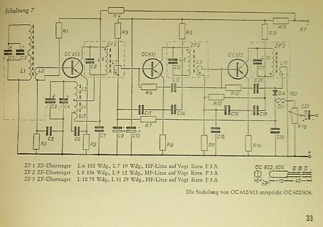
 Bild
 Bild
 Bild