angle • 4.3~15.3 mm actuator • through hole SPECIFICATIONS parameter conditions/description min typ max units rated voltage 1 12 Vdc rated current 0.01 50 mA withstanding voltage for 1 minute 250 Vac contact resistance applying load of 2 times operating force at 5 Vdc, 10 mA 100 mΩ insulation resistance
7mm. Der Reihenabstand ist 6mm. Die Steckkontakte für die Buchsen müßten etwa 3-3,2mm Breit und max. 9-10mm Lang sein. Dicke ca. 1mm.
Auszieh-Montage-Demontage-Werkzeug (insertion and extraction tool) heißt 753787-1 und kostet zwischen 84 und 105 Euro, z.B. bei Bürklin, Farnell, C, erhältlich. Die Crimpzange (hand tool 755402-1) ist schwieriger zu bekommen, weder Digikey noch Mouser listen sie.
Indicators PWR1, PWR2, PoE, FAULT, STATE, SIGNAL, WLAN, LAN Input/Output Interface Digital Inputs 2 Max. input current: 8 mA +13 to +30 V for state 1 +3 to -30 V for state 0 Alarm Contact Channels Relay output with current carrying capacity of 1 A @ 24 VDC Buttons Reset button Physical Characteristics Housing Metal IP Rating IP30 Dimensions 52.7 x 135 x 105 mm (2.08 x 5.32 x 4.13 in) 4 www.moxa.com Weight 860 g (1.9 lb) Installation DIN-rail mounting Wall mounting (with optional kit) Power Parameters Input Current 0.6 A @ 12 VDC, 0.15 A @ 48 VDC Input
@ 24 VDC Digital Input Channels 2 Digital Inputs +13 to +30 V for state 1 -30 to +3 V for state 0 Max. input current: 8 mA Ethernet Interface 10/100BaseT(X) Ports (RJ45 connector) EDS-508A Series: 8 EDS-508A-MM/SS Series: 6 All models support: Auto negotiation speed Full/Half duplex mode Auto MDI/MDI-X
256 MAC Table Size EDS-405A, EDS-405A-EIP/MM-SC/MM-ST/PN/SS-SC models: 2 K EDS-405A-PTP models: 8 K Max. No. of VLANs 64 Packet Buffer Size 1 Mbits Priority Queues 4 VLAN ID Range VID 1 to 4094 Serial Interface Console Port RS-232 (TxD, RxD, GND), 10-pin RJ45 (115200, n, 8, 1) DIP Switch Configuration
...................................................................................................105 Figure 97: Transmission of the correction factors........................................................................................................................................105 Figure 98
square wave input DC to 50 MHz clock Internal clock references 48 MHz internal IRC (FIRC) with 1.1% max deviation across 48 MHz internal IRC (FIRC) (IRC) full temperature with 1.4% max deviation across full temperature 8 MHz internal IRC (SIRC) with 3.3% maximum deviation across full temperature 8 MHz
Sicherung/Fuse e th offen bei 40°C / open at 40°C 380-440V 500-690V „Typ1“ gL (gG) Typ / Type A kW kW A max. e K3-24A00.. 50 11 15 80 t n K3-32A00.. 65 15 18,5 80 u o K3-40A00.. 80 18,5 18,5 80 i w g a c Hilfsschaltglieder / Aux. contacts HN10, HN01 t AC1 l (=l ) AC15 AC15 Sicherung/Fuse t e th j offen bei 40°C / open at 40°C 220-240V 380-440V „Typ1“ gL (gG) u Typ / Type A A A A max. s e K3-24A00..+HN.. 10 3 2 20 s o K3-32A00..+HN.. 10 3 2 20 t i K3-40A00..+HN.. 10 3 2 20 c p S n l a e o v e Approbationen / Approvals n r d Nordamerika Schweiz Europa Russland China n North America
116 73 C609 T 39 21 C809 T 10 54 C920 T 85 75 C1415 T 53 75 L307 T 134 34 R121 T 17 85 R535 T 125 105 C200 T 134 19 C610 T 39 16 C810 T 28 64 C921 T 105 99 C1416 T 45 103 L308 T 87 52 R122 T 17 86 R601 T 71 49 C201 T 136 19 C611 T 37 19 C811 T 18 59 C922 T 97 98 C1417 T 43 103 L400 T 17 28 R123 T 26
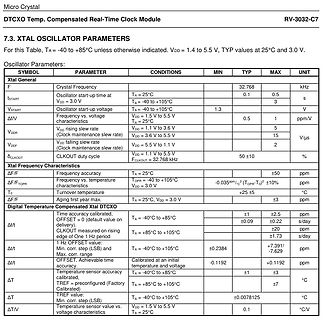
= 1.4 to 5.5 V, TYP at 25°C and 3.0 V.
Oscillator Parameters:
SYMBOL PARAMETER CONDITIONS MIN TYP MAX UNIT
F Xtal Frequency 32.768 kHz
tSTART Oscillator start-up time at TA = 25°C 0.1 0.5 s
VDD = 3.0 V
VSTART Oscillator start-up voltage TA = -40 to +105°C 1.3 V
F frequency vs. voltage characteristics
Mal den Pförring-Maxe fragen, der hat vielleicht noch Referenzware vergleichbaren Alters auf Lager :P Für den vorgeschlagenen Zehntel des Preises könnte man ein Punktschweißgerät für Akkuzellen daraus bauen. (Nur mal
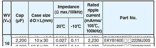
000 h • Upper category temperature (105 °C) • Negative terminal identification Shelf life at 0 V, 105 °C 1000 h Based on sectional specification IEC 60384-4 / EN130300 • Series number (150) Climatic category IEC 60068 55 / 105 / 56 SELECTION
Was recht aufschlussreich ist, ist die Lebensdauer der original verbauten Elkos: Shelf life at 0 V, 105 °C 1000 h.
recht aufschlussreich ist, ist die Lebensdauer der original > verbauten Elkos: Shelf life at 0 V, 105 °C 1000 h. Erstaunt mich nicht, es muss schliesslich billig sein und mit Serviceleistungen verdient man Geld. Das Auslaufen hat allerdings mit den 1000h/105° wenig zu tun. Da ist einfach die Qualität
extended periods may affect device reliability. NOTES: 1. Maximum power dissipation is a function of T (max), and T . The maximum allowable power dissipation at any allowable ambient temperature is = (T (max) – T )/ . Operating at the absolute maximum T of 150⋅C can affect reliability. Due to D J A JA J variations
Projektbezogen. Soweit ich verstanden habe, würde bei 12V der Akku ja nicht voll werden, weil man unter der max. Ladespannung liegt und bei 15V läuft man Gefahr den Akku zu rösten, wenn wirklich keine Elektronik dazwischen sitzt, die das verhindert. Leider ist die Website vom Forumslader da für mich irgendwie
anzuschließen. Also nochmal - schließ dein 3S Ladeboard an den Solareingang an. Wähle eins das max 1.5A ausgibt. Was fehlt dir noch?
5V ± 10%; VPPP = VCC ) M2tCe001 Symbol Alt Parameter Test -55 (2) l-70 -80 -90 Unit Condition o Min Max s Min Max Min Max Min Max t t 55 70 80 90 ns AVQV ACC to Outputalid G = VIL - O Valid IL ) ( s ELQV tCE Chip Enable c = VIL 55 70 80 90 ns Valido Outputu o d GLQV tOE OutputEnable E = VIL 30 35 40 40
Michael H. schrieb im Beitrag #8043509: > max. bis 40 MHz. Bis dahin kannst du auch noch Steckbretter verwenden, bis 30 MHz gar kein Problem und an den 40 MHz wird es nicht scheitern. Ich habe schon Doppelsuper bis 30 MHz auf dem Steckbrett
Bernhard S. schrieb im Beitrag #8043520: >> max. bis 40 MHz. > > Bis dahin kannst du auch noch Steckbretter verwenden, bis 30 MHz gar > kein Problem und an den 40 MHz wird es nicht scheitern. Wenn der Transistor aber eine Grenzfrequenz von
47–49 Hz frühere Safe-&-Sound-Pro-II-Aufzeichnungen im Bereich 200 MHz–8 GHz mit auffälligen Peak-/Max-Werten; Gerät ist inzwischen nicht mehr da vorhandene Zeitfenster, Audio/Video und Phyphox-/Handy-Sensordaten zur zeitlichen Zuordnung Die gesundheitliche Seite ist leider real bei mir; ich lag
Jörg W. schrieb im Beitrag #8046903: > um ca. 48 Hz Das sind Asynchronmotoren. Die 105Hz koennten von Universalmotoren stammen.
auf die Fragestellung zu erhalten. Nach meinen Recherchen besteht lediglich der Unterschied beim max Dauerstrom / Einschaltstrom bisher 10/20A neu 16/30A. Das sollte eher besser als schlechter sein. Max Schaltleistung AC1 bisher 2500VA, neu 4000VA. Max Schaltleistung AC15 (230V) bisher 500VA, neu 750
4ct genügt aber auch: https://www.reichelt.de/de/de/shop/produkt/elko_radial_1_0_f_100v_rm2_5_1000h_105_c_20_-42393
AgSnO +20,2 µm Au; AgNi + 5 µm Au 2.3 Bemessungsisolationsspannung AC 250 V 4) Schaltspannung min. / max. AC/DC 12V/DC250V,AC400V(≈105)V/≈60V) AC/DC 12 V / DC 250 5) AC 400 V 2.4 Grenzdauerstrom I mth. 10 A 16 A Schaltstrom min./max. 10 mA 7)/ 16 A (1 mA / 0,3 A)4) 0,3 A / 25 A 2) 2.5 Schaltleistung min
taken with nominal devices at room temp). 1V8_IN 3V3_IN PARAMETER TEST CONDITIONS UNIT TYP MAX TYP MAX 1 DSSS TX Power = 17.9dBm 92 270 310 6 OFDM TX Power = 17.8dBm 110 170 270 320 54 OFDM TX Power = 15.5dBm 115 215 Continuous TX(1) HT MCS0 TX Power = 17.8dBm 110 270 mA HT MCS7 TX Power = 15.5dBm
ELECTRICAL CHARACTERISTICS COMMON TO ALL VERSIONS Unless otherwise noted: 4.5V ≤ VCC ≤ 5.5V, -40°C ≤ TA≤ 105°C, I (Vout) = I (Vref) = 0 (Recommended Operating Conditions). Typical values are for VCC = 5V and TA= 25°C. CONFIDENTIAL Parameter Symbol Test Conditions Min Typ Max Unit Vout Output Increase I (Vout
operating cycles Inrush current limiters are not damaged when directly connected to V even without max additional current limitation Flame-retardant plastic case Type J105, J107 and J109 Case material UL-listed Sn-plated lead-free solder pins Manufacturer's logo, type designation and date code YYWW stamped
the counter is full (therefore the counter is also presettable for the DOWN-phase to get a defined max. DOWN-timing in case of a fault). When the DOWN-phase is ready, the contents of the counter is transferred to the output shiftregister and the AZ-phase is started. The timing of the AZ~phase is done
0 . 6 . .e e e. e e s 104 a3 Fig. 62. Powersupply circuit diagram 22... k e e e e ee eee eee ee es 105 Fig. 63. Analog section circuit diagram .. 0.0... c e e e e ete ee eee eee eee eee 110 Fig. 64. Digital section circuit d i a g r a m .e e e .t e e .eee e e 111 ' Fig. 65. Modifications in active filter
button “zero set on/off” 1.6. D C C U R R E N T M E A S U R E M E N T S Ranges :20mA,20mA,2.4,208 (max, input current in highest range) #10 A (20 A for max, 20 sec.) Resolution 510HAin20mArange Number of representation units £2200 Acuracy ++(0.5%ofreading+0.1%offulscale) Temperature coefficient +0.05%
measure anode luminous sensitivity) VOLTAGE 0 V ON LIGHT LEVEL OFF 5 6 7 8 9 (minutes) 1 µA ANODE I max. OUTPUT Ii I min. OR Ii I max. I min. 5 6 7 8 9 (minutes) WARM-UP PERIOD (5 minutes or more) THBV4_0440EA Figure 4-40: Light hysteresis In light hysteresis test, the photomultiplier tube is operated
TS13003 High Voltage NPN Transistor TO-92 Mechanical Drawing TO-92 DIMENSION MILLIMETERS INCHES DIM MIN MAX MIN MAX A 4.30 4.70 0.169 0.185 B 4.30 4.70 0.169 0.185 C 14.30(typ) 0.563(typ) D 0.43 0.49 0.017 0.019 E 2.19 2.81 0.086 0.111 F 3.30 3.70 0.130 0.146 G 2.42 2.66 0.095 0.105 H 0.37 0.43 0.015 0.017
15V, T = 25°C, RL = 10k? unless otherwise noted. VRE117/118/119 MODEL C CA M MA PARAMETERS MIN TYP MAX MIN TYP MAX MIN TYP MAX MIN TYP MAX UNITS ABSOLUTE MAXIMUM RATINGS Power Supply ±13.5 ±22 * * * * * * V Operating Temperature -25 85 * * -55 125 -55 125 °C Storage Temperature -65 150 * * * * * * °C
SPECIFICATIONS Vps =+15V, T = 25°C, RL = 10Kotherwise noted. VRE104 MODEL C CA M MA PARAMETERS MIN TYP MAX MIN TYP MAX MIN TYP MAX MIN TYP MAX UNITS ABSOLUTE MAXIMUM RATINGS Power Supply +13.5 +22 * * * * * * V Operating Temperature -25 85 * * -55 125 -55 125 °C Storage Temperature -65 150 * * * * * * °C
FM IF INPUT SIGNAL OUTPUT SET RADIO ADJUST ADJUST FOR REMARK TP8 10.7MHz TP3,4 Quiet Point T101,102 Max. o/p symmetricaVol. at min. position 2) RF VOLTAGE BAND SIGNAL OUTPUT SET RADIO ADJUST ADJUST FOR REMARK FM - - TP2,5 108MHz L102 1.7V~ 2.3V high end 7.3V ~7.7V 3) FM RF INPUT SIGNAL OUTPUT SET RADIO ADJUST ADJUST FOR REMARK TP1,2 90MHz Speaker 90MHz L101 Max. o/p Vol. at max. position TP1,2 106MHz „ „ 106MHz TC102 „ „ „ „ 4) 75KHZ CRYSTAL OUTPUT ADJUST ADJUST FOR REMARK TP6,7 CHECK ONLY 75KHz± 10HZ 5) 1.8432MHZ CRYSTAL OUTPUT ADJUST ADJUST FOR REMARK TC201
Melting I t Part Number Rating (A) (mm2) 755 Ir (mV) Resistance (mΩ) (A s) 0878450.UX-XXX 450 35 60 0.105 810 492 2 Note: The typical I t is an average value calculated from the breaking capacity tests by using the melting time before the arcing occurs. Dimensions Dimensions in mm. Please refer to the outline
LED3 +12V V7 -12V LED4 -12V V8 +12V Power supply unit G2 Output voltages Output voltage Min. load Max. load Comments +5V 3.0A 15.0A +12V 0.5A 5.0A -12V 0.0A 0.7A -5V 0.0A 0.3A not used Checking and setting Power supply unit G2 does not have any sensor lines to compensate the voltage drop through the
Schnittstelle Cortex M3 Core - STM32 F1 series of mainstream MCUs STM32F103 : 1 CAN Schnittstelle STM32F105 : 2 CAN Schnittstellen STM32F107 : 2 CAN Schnittstellen - STM32 F2 series of high-performance MCUs STM32F205 : 2 CAN Schnittstellen STM32F207 : 2 CAN Schnittstellen STM32F215 : 2 CAN Schnittstellen
erhältlich z. B. bei Reichelt: SN65HVD230, SN65HVD231 (ca. 3,00 €) Datenblatt: SN65HVD230 SN65HVD231 MAX3051EKA/ESA. von Analog (fka Maxim) SOT23-8 und SO-8 als SOT23 noch gut manuell zu verarbeiten, dabei relativ klein VCC = 3,3V, trotzdem voll kompatibel erhältlich z. B. Mouser, Digikey, LCSC Datenblatt
Gedanke ist echt interessant. Habe zwischen meinem Internetrouter und einem WLAN-Router ein Netgear GS105E angeschlossen. Über den WLAN-Router war nur die Solarbank verbunden. Mit dem Netgear GS105E kann man mit einem Rechner und Wireshark den Datenverkehr zwischen Internet und der Solarbank auslesen.
Die neue Anker Solix 4 und die die Max AC sind ModBus TCP fähig und es gibt eine offizielle Home Assistant Unterstützung. Vielleicht stellt Anker das auch noch für die Solix 3 zur Verfügung.
abgespeichert. Ist sin_position > 15, wird das Array xistor_i[] ausgewertet, um die Posistion xistor_i_max_position des größten Wertes xistor_i_max_value zu bestim- men. Mithilfe dieser beiden Werte wird anschließend die Verzerrung zur Regelung der Brückentreiberlogik berechnet (siehe Kapitel 5.6). Das Auslesen
CHAdeMO Input AC power connection 3P + N + PE Input voltage range 400 V AC+/-10% (50 Hz or 60 Hz) N Max. rated input current & power 125A, 86 kVA F 1 Power factor (full load) > 0.96 3 0 Efficiency 95% at nominal output power 2 DC output V 4 Maximum output power 50 kW d r Output voltage range 200 – 500
180 kBit/s, bei Bus, Halb-Duplex Protokolle 375 kBit 300m, bei 500 kBit 200 m IO-Link IO-Link 40 m Max 230,4 kBit/s, Nein M12 Nein Halb-Duplex 4-20 mA Analog-Schnitt- 200 m und mehr -/- Ja, circa 36 mA Schraubklemme Ja stelle HART® Digital moduliert 200 m und mehr 1200 bit/s, Halb- Ja, circa 36 mA Schraubklemme
TABLE servicing. Failure to do so could result in death or serious injury. INSULATION RATING: CLASS A (105°C) TEMPERATURE RISE: 65°C RISE ABOVE 40°C FIRE HAZARD AMBIENT Do not exceed transformer ratings. DIELECTRIC STRENGTH: 1500 VRMS Higher voltage may damage control and could cause personal injury or NOTE: property damage. 1. All leads 8" long minimum. D D MAX. MAX. 2 H MAX. H R z 2 MW MAX. O X 6 1 1 W C X R5 MAX. N P P7 T 1 S .188 ± .015 DIA. (2 HOLES) STYLE A 1 3 MD MW W MAX. PRIMARY SECONDARY 117V, 50/60 Hz 4 24V CT MS (4 PLACES) STYLE NV 2 5 SCHEMATIC

 Bild
 Bild
 Bild