5: HLMP-2450/2755/2770Annunciators (0.2 × 0.8 Yellow H 116.50 227.70 and 0.4 x 0.4 Yellow) I 186.30 364.40 IV Bin Category Min. Max. a. Minimum category A for Deep Red (-B100/-C100/-G100). C 13.00 22.00 b. Minimum category D for Red (-2350/-2670). D 18.00 33.00 E 27.00 50.00 F 40.50 81.00 G 65.60
4X ș1 R1 H R c SEATING PLANE C L ș (L1) 4X ș 1 DETAIL B Units MILLIMETERS Dimension Limits MIN NOM MAX Number of Terminals N 8 e Pitch 0.65 BSC Overall Height A – – 1.10 Standoff A1 0.00 – 0.15 Molded Package Thickness A2 0.75 0.85 0.95 Overall Length D 3.00 BSC Overall Width E 4.90 BSC Molded Package
+ − 50 A/ s T2+ G− − 50 A/ s T2− G− − 50 A/ s T2− G+ − 10 A/ s I gate current (peak value) t = 2 s max − 1 A GM V GM gate voltage (peak value) t = 2 s max 5 V P GM gate power (peak value) t = 2 s max − 5 W P G(AV) average gate power T case 80 °C; t = 2 s max − 0.1 W T stg storage temperature −40 +150
sentido horário, [MULTICHANNELDECODING],SOUNDFIELD[2CH],SOUND “VOL MIN”, “VOL 1” para “VOL 30”, “VOL MAX” aparecem. CONTROL [SURR] e [NAME] LED acendem. 4. Pressione a tecla [VIDEO 1] , todos os seguimentos apagarão. 5. Toda vez que pressionar a tecla [VIDEO 1] um conjunto de seguimento e LED acenderá
with DMA controller 8-bit camera interface (up to 80 MHz) 11 analog peripherals 3x ADCs with 16-bit max. resolution (up to 36 channels, up to 3,6 MSPS) 1x temperature sensor 2x 12-bit D/A converters (1 MHz) 2x ultra-low power comparators 2x operational amplifiers (7.3 MHz bandwidth) 1x digital filters
Vb 1 7867 o t a l t ED ED ED s n I a b ED ED Va Vb a b ED ED Va Vb a b ED ED Va Vb 1 7867 ED ED ED max. 30 max. 30 max. 30 L N Va Vb L N Va Vb L N Va Vb 1 6481 L N 1 2 3 4 11 21 a1 b a2 b a3 b 1 7573 Va Vb Va Vb + E+ Va Vb Va Vb 1 4813 1 8783/ Va Vb 80 1 2 1 8789 LT 1 2 3 4 1 8759/ 1 8760 1 8753 S0251
Reset 5 V FEEDBACK V D Q STATE (FB) TH - MACHINE VILIMIT tSAMPLE-OUT ILIM Drive CABLE DROP VILIMIT DC MAX COMPENSATION FAULT 6.5 V FB Auto-Restart Open-Loop INDUCTANCE THERMAL CORRECTION SHUTDOWN tSAMPLE-INPUTX tSAMPLE-OUT SAMPLE t DELAY SAMPLE-INPUT OSCILLATOR SOURCE + (S) I SOURCE CONSTANT LIM - VILIMIT
SSB Adjust the correct x, y coordinates (while holding one of the White point registers R, G or B on max. value) by means of 6.1 General Alignment Conditions decreasing the value of one or two other white points to the Perform all electrical adjustments under the following correct x, y coordinates (see
differential pair, the transducer's layout used a cross-quad geometry. Variations in process parameter A .v max(A),max(B) min(A),max(B) Variations 1/2 of device 1 1/2of device 2 in process . parameter B l _ II _ max(A),min(B) min(A),min(B) F 1/2 of device 2 1/2 of device 1 Figure 3.15: Cross-quad layout sketch
Dieser Strom kommt über D601. Bei INH = Low ist IC602 im Stand-by-Modus und nimmt bei VDD = 5 V max. 15 µA und bei VDD = 2 V max. 5 µA auf. Auch wenn man den Leckstrom des Kondensators C620 vernachlässigt, reicht 2,2 mF an VDD keine Stunde, vielleicht aber typisch. Bis INH beim Ausschalten den
Aufnahme bei VDD = 5V (Annahme VDDmin = 3V) kommen bei 2.2mF und 2.2F keine großen Zeiten raus, ca.380s max. Dann auf VDD = 2 (Sparstufe, Annahme VDDmin = 1V) und 5mA, aber auch nicht viel mehr, ca. 600s max. 5/0.015 = 330, 2/0.005 = 400 --> ca. 330 - 400 Ohm. Ganz einfach ohne viel rechnen mal 380
<a href="#fn48" class="footnote-ref" id="fnref48" role="doc-noteref"><sup>48</sup></a></p> <h2 id="max-max_y"> Max (max_y) </h2> <p>Softmaker Freeoffice wurde ja schon erwähnt. Momentan gibt es sogar das große Softmaker Office Paket kostenlos, ist aber die Version von 2021. Dennoch sicherlich einen Blick
85 ℃ Storage Temperature Tstg -40~ +85 ℃ Lead Soldering Temperature Tsol 26℃ /10sec - *Pulse width Max 0.1ms, Duty ratio max 1/10 ■ Electrical -Optical Characteristics (Ta=25℃) V FV) R (µA) Iv(mcd) λD(nm) 2θ1/2(deg) Part Number Color Min. Typ. Max. Max. Min. Typ. Max. Min. Typ. Max. Typ. F =5mA V R5V
output impedance.IC to the active area + 1/160 1/12 7.93% e 6.3% 5.7% In addition, please limit the min-max spread of RC decay to 1/160 1/11 7.77% 6.2% 5.6% be: f i | RC MAX– RC MIN | < 0.15 S VIDEO CSTN & COG applications. For LCM with r ft = 180mS ~ 200mS or smaller, bottom of the screen are uniform.e top
test are the same and the very only difference is a FMC speed of 220MHz (because I've read of 110MHZ max FMC speed here: https://community.st.com/t5/stm32-mcus/how-to-set-up-the-fmc-peripheral-to-interface-with-the-sdram/ta-p/49457 ), but the 240MHz makes no substantial differences (only in decimals).
EPX880 & EPX8160: I = 12 mA DC, V = min., 0.2 V OL CCO current Note (4) I Input leakage current V = max., GND < V < V , Note (5) –10 10 A I CCO IN CCO OZ Output leakage current EPX880 & EPX8160: V CCO = max., OUT = VCCO –50 50 A EPX880 & EPX8160: V CCO = max., OUT = GND –100 100 A SC Output short circuit
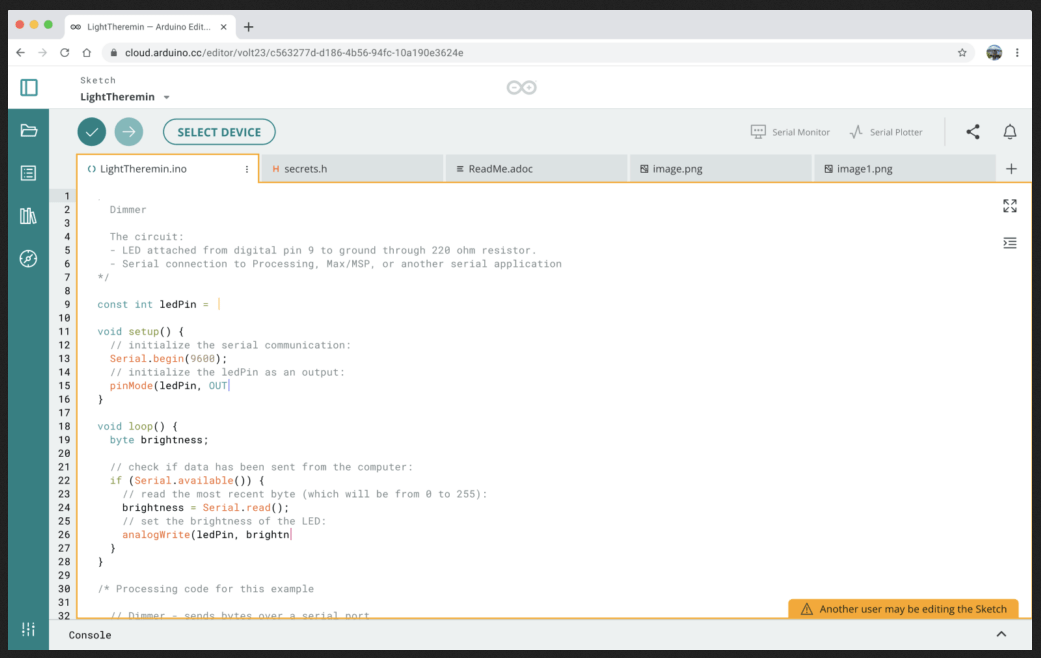
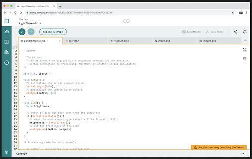
LightTheremin - Arduino Edit...
cloud.arduino.cc/editor/volt23/c563277d-d186-4b56-94fc-10a190e3624e
LightTheremin
SELECT DEVICE
Serial Monitor
Serial Plotter
LightTheremin.ino
secrets.h
ReadMe.adoc
image.png
image1.png
Dimmer
The circuit:
- LED attached from digital pin 9 to ground through 220 ohm resistor.
- Serial connection to Processing, Max/MSP, or another serial application
*/
const int ledPin =
void setup() {
// initialize the serial communication:
Serial.begin(9600);
// initialize the ledPin as an output:
pinMode(ledPin, OUT);
}
void
den Nennvolumenstrom. Folgende Richtwerte sollten dabei nicht überschritten werden: dp = 120 Pa/m max von Rohrleitungen DN 10 bis DN 65 w max = 0,7 m/s von Rohrleitungen DN 80 bis DN 125 w max = 1,2 m/s ab Rohrleitungen DN 150 w = 2,0 m/s max Subject to change and error 20/327 Version 11/2021 Abb. 0.8
which has two extreme values along the hysteresis curve Bx,1− B x,2 B x,1− B x,2 µmin = min , and µ max = max . (5.58) H x,1Hx,2H x,1− H x,2 Hx,1,Hx,2H x,1− H x,2 Hereµ min andµ max aretheminimumandmaximumslopeofthehysteresischaracteristics. The inequality µmin ≤ µ ≤ µ max (5.59) is obvious, from which
ersetzt. Solarladeregler 18122 12/24V 1,5mA 4Aout 18122 68x57x28mm 2x IRFZ24N min10,5V Reset12,5V max13,8V 4A Conrad 200013 9€, 20A MPPT Solar Panel Battery Regulator Charge Controller 12V 24V Auto Switch Zur Überwachung der Akkuspannung ist eine 99,9V LED-Anzeige 3 Digit (Ub=4-30V 20mA) mit 1um
110W 17l/min 1020l/h Thermal Protection InOut1/2" 12.7mm Port3/4” 19mm 4 Chambres, Self-priming2m, max.40PSI 2,76bar Run Dry 54,63€ https://de.aliexpress.com/item/1005002985985096.html Der Ausgang der Pumpe wird noch über zwei elektronisches Kugelventil 12V 80mA CR01 bzw. CR02 umgeschaltet. Es braucht
Hallo, ich bin auf Fehlersuche an einem 186er Motherboard, von einer alten Sinumerik 810 CNC Steuerung. Die CPU ist ein SAB80186-R, wovon ich in Netz kein Datenblatt gefunden habe. Die Schaltung besteht im Wesentlichen aus der CPU, 74er
Michael schrieb im Beitrag #7710072: > ich bin auf Fehlersuche an einem 186er Motherboard Welchen Fehler hat es denn ? Gruß
cycles D and D are less than D . In this case, the first, simple equation can always be used. 1 2 MAX 2. One duty cycle is greater than D MAX and the other duty cycle is less than D MAX . In this case, the system designer can take advantage of the fact that the sync feature reduces D MAX for one channel
200 0 3 VEN V - 100 DC-INPUT 8 I P CLOCK 0 10 D MAX V 5 BYPASS 0 IDRAIN 400 200 V DRAIN 0 0 1 2 Time (ms) VDRAIN Figure 11. TinySwitch-II Power-up without Optional External UV Resistor Connected to EN/UV Pin. 0 PI-2661-072400 0 - Figure 9. TinySwitch-II
place.The compressors will withstand storage temperatures down to -35°C. Condensing temperatures: Max. 60°C at stable conditions and max. 70°C at peak load. Ambient temperatures: Min. -10°C, max. 55°C The BD compressor concept includes an electronic unit which features overload protection, battery protection
6080 6,3V / 10A 63W Heizkreis allgemein 6,3V / 2,6A 16W potentialfrei C C für +170V 230V PRI 230V PRI 186V / 0,16A für -130V 30W 148V / 0,16A 24W 186V / 0,16A Zweiweggleichrichtung Leistung wird immer nur aus Zweiweggleichrichtung einer Wicklung entnommen 148V / 0,16A Leistung wird immer nur aus einer Wicklung
RELATED TO THE INFORMATION OR Inter-Chip Connectivity, JitterBlocker, Knob-on-Display, MarginLink, maxCrypto, maxView, memBrain, Mindi, MiWi, MPASM, MPF, MPLAB ITS USE, HOWEVER CAUSED, EVEN IF MICROCHIP HAS Certified logo, MPLIB, MPLINK, mSiC, MultiTRAK, NetDetach, BEEN ADVISED OF THE POSSIBILITY OR
CCCV Step-Down gäb's passende, auch incl. Digital-Anzeige. Also Speisung m.o.w. (Spannungsfall @ I_max abh. v. genauen Step-Down unterschiedlich) deutlich oberh. der gewünschten U_aus(max) vorsehen. Wäre übrigens kein echtes Problem, weil man sowieso diverse Rails (auch noch viel höhere und evtl
eigentlich nötigen Kommentar: EAM86, EBC90, EBC91, EBF80, EBF83, EBF89, EC91, ECC81, ECC82, ECC83, ECC186, ECH83, ECH84, ECL80, EF80, EF85, EF91, EF93, EF94, EF96, EF97, EF98, EF183, EF184, EH81, EH90, EK90, EM83, EM85, EM87, EM800, EM801 und die wurden auch in Fernsehgeräten verbaut, sofern notwendig
>3 >4 >5 >6 >2 3 >4 >5 >6 >2 >3 >4 >5 6 B supported by the device. WAPP is only 963 lines of code. max Wear-out Indicator Increment Next, we experimented with the difficulty of hiding a malicious, I/O intensive application on Android. We observe two likely indi- Figure 4: Time to increment wear-out indicators
ambiAnt, T , and internal leadframe temperA ures, T , provided that the Maximum Junction Temperature, J(max), is not exceeded. 21G = 0.1 mT. 3R forms an RC circuit via the FILTER pin. F(INT) COMMON THERMAL CHARACTERISTICS 1 Min. Typ. Max. Units Operating Internal Leadframe Temperature TA E range –40 – 85
AAA Energizer Max (Singapore) AAA Energizer Max aus IR-FB gebr. MHD 12-2030 MHD 12-2030 Kauf 10-2020 Kauf 10-2020 17. Oktober 2021 15. Mai 2024 Entladung mit: 30 mA Entladung mit: 30 mA mAh max: 1197 mAh max: 1100 Time
. There are two cases that give a transition without Compare Match. OCR0A changes its value from MAX, like in Figure 15-7. When the OCR0A value is MAX the OCn pin value is the same as the result of a down-counting Compare Match. To ensure symmetry around BOTTOM the OCn value at MAX must correspond
to a value Counter wraps around lower than CNT MAX "Interrupt" CNT TOP BOTTOM Timeout Check Mode In this mode, the counter counts to MAX and wraps around. On the first edge the counter is restarted and on the second edge the counter is stopped. If the

 Bild
Bild
 Bild
Bild
 Bild
Bild
 Bild
Bild