for Time Signal Application Manufacturer Antenna Type Dimensions Web Link Micro Analog A10X60-77.5K222PY ø 10 x 60 mm http://www.mas- Systems Oy A10X100-77.5K222PY ø 10 x 100 mm oy.com/en/products/radio-controlled- A3.5X4X15-7.87MH 3.5 x 4 x 15 mm clock-rcc/antennas/ A2X3X21-0.92MH 2 x 3 x 21 mm A3.75X3.75X23.6
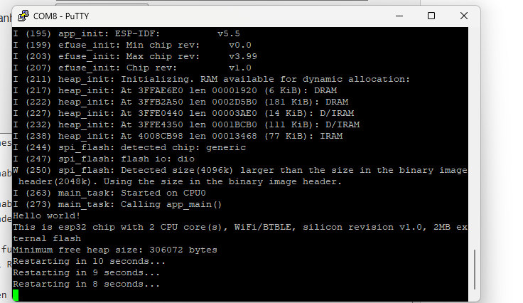
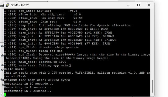
- PuTTY
I (195) app_init: ESP-IDF: v5.5
I (199) efuse_init: Min chip rev: v0.0
I (203) efuse_init: Max chip rev: v3.99
I (207) efuse_init: Chip rev: v1.0
I (211) heap_init: Initializing. RAM available for dynamic allocation:
I (217) heap_init: At 3FFAE6E0 len 00001920 (6 KiB): DRAM
I (222) heap_init:
channel 6 N7 Close channel 7 N8 Close channel 8 N9 Close channel 9 N10 Close channel 10 N11 Step mode, max channel is 2 N13 Step mode, max channel is 4 N14 Step mode, max channel is 5 N15 Step mode, max channel is 6 N16 Step mode, max channel is 7 N17 Step mode, max channel is 8 N18 Step mode, max channel is 9 N19 Step mode, max channel is 10 N20 Open all - stop scanning or stepping if applicable Scanning (cont.) N21 Scan mode, max channel is 2 N22 Scan mode, max channel is 3 N23 Scan mode, max channel is 4 N24 Scan mode, max
: 74h Size: 8 bits Table 3-213 Lock Count Bit Access Symbol Description [7:4] R/W locked_cnt_noisy_max These bits set the max value of the hlock sensor for noisy signals. 8 is added to this value. Default = 7 stands for 15. These bits set the max value of the hlock sensor for clean signals. 8 is [3:0] R/W locked_cnt_clean_max added to this value. Default = 4 stands for 12. 3.9.18 H Loop Max State Address Offset: 17h Access: Read/Write Default Value: CBh Size: 8 bits 83 电子专业技术主页: HTTP://WWW.LCDHOME.NET 资料收藏: 版权归原作者所有 谨供学习用
ja nun mal kein Präzisionsteil, auch wenn da was von very low input offset voltage steht, was mit max. 13mV aber immer noch ein Witz ist. Also wäre eine Zahlenangabe mal nicht schlecht, in Zusammenhang mit einem dimensionierten Schaltplan.
Prüfmethode seit 20Jahren unverändert (Schaltung werde ich nicht veröffentlich) Wenn 053K für das Jahr 222(0) steht, dann ist das Bauteil doch überlagert?
20 A1, Frequenz- Smart PLGS 2012 A1. leistung.......≤20dBm Frequenzband ..2400-2483,5MHz Temperatur.max 50 °C Ladevorgang 0 - 10 °C, bzw. 50 - 60 °C bei einem Ladestrom von max. 4 A 10 - 50 °C bei einem Ladestrom von max. 12 A Betrieb......-20 - 50 °C Lagerung 8 DE AT CH Ladezeit Akku Smart PAPS 208 A1
Netzteil: LED Driver 5Wx1 LED 680mA Model: DRI5W680B Pri. 220-240V, 50/60Hz Sec. 0,68A max.10,5V max.5W weißes Plastikgehäuse mit den Maßen LxBxH 41x30x22 mm³ Transistor (?): Q1, Bauform TO-126, Beschriftung: 1039H SPS 13003 Das ist vermulich ein
regel-loop) 12V NT auf 10.5V ändern Das Netzteil ist ein Konstantstromnetzteil; da steht 680 mA und /max/ 10.5 V.
056 056 000 - 446352 194 Temperature_Celsius -O---K 100 100 000 - 37 (Min/Max 10/57) 222 Loaded_Hours -O--CK 008 008 000 - 37024 [/code] Der Server startet jeden Tag morgens um 7 Uhr und läuft bis 23 Uhr, bisher ohne irgendwelche Probleme. Backups
056 000 - 446352 > 194 Temperature_Celsius -O---K 100 100 000 - 37 (Min/Max > 10/57) Hallo Chris D., 193 Load_Cycle_Count -O--CK 056 056 000 - 446352 194 Temperature_Celsius -O---K 100 100 000 - 37 (Min/Max 10/57) auch Du solltest
place.The compressors will withstand storage temperatures down to -35°C. Condensing temperatures: Max. 60°C at stable conditions and max. 70°C at peak load. Ambient temperatures: Min. -10°C, max. 55°C The BD compressor concept includes an electronic unit which features overload protection, battery protection
generated when the counter is equal to TOP. If TOP is updated to a value lower than count upon reaching MAX the counter restarts from BOTTOM. Figure 21-3. Periodic Interrupt Mode MAX and Event) Request TOP CNT BOTTOM TOP changed to CNT set to BOTTOM a value lower than CNT 21.3.3.1.2 Time-Out Check Mode In
(ground = 0 V). Symbol Parameter Conditions 25 °C -40 °C to -40 °C to Unit +85 °C +125 °C Min Typ Max Min Max Min Max 74HC08 V HIGH-level V = 2.0 V 1.5 1.2 - 1.5 - 1.5 - V IH CC input voltage VCC = 4.5 V 3.15 2.4 - 3.15 - 3.15 - V VCC = 6.0 V 4.2 3.2 - 4.2 - 4.2 - V VIL LOW-level VCC = 2.0 V - 0.8 0.5
(non green material) Solder (green material) Process Average Ramp Up Rate (T ts T )p 3°C / second Max. 3°C / Second Max. Preheat - Temperature Min (T sin.) 150°C 100°C - Temperature Max (T Msx.) 200°C 150°C 60 to 120 seconds - Time (s Min to s Max) 60 to 120 seconds Time Maintained Above Critical Temperature
(non green material) Solder (green material) Process Average Ramp Up Rate (T ts T )p 3°C / second Max. 3°C / Second Max. Preheat - Temperature Min (T sin.) 150°C 100°C - Temperature Max (T Msx.) 200°C 150°C 60 to 120 seconds - Time (s Min to s Max) 60 to 120 seconds Time Maintained Above Critical Temperature
truth, but the amount of extra voltage swing that is achieved is hard to calculate. Guaranteed min/max specifications define the limits of a parameter. The parameter will always exceed the minimum value, and it will never exceed the maximum value. The guaranteed min/max specifications are your design
connection switch Y 5 n sectionneur principal F 2 t 0 / t 1 2 e 1 M l Flur W a floor atelier 3 l Spannweite max.(m) 1 p Hubmotor span max. (m) Hängesteuergerät Typ W s z portée max. (m) 0 suspended control paneltype H (Klammerwerte bei Kaltleiter) hoist motor 1 boîte de commande 5 W15 (mm²) 1 STH 0 n / (values
REF = 4.096 V (internal), SDO load = 20 pF, and f SAMPLE = 500 kSPS, unless otherwise noted. MIN TYP MAX UNIT TIMING SPECIFICATIONS fS Sampling frequency (f CLK = max) 500 kSPS tS ADC cycle time period (f CLK = max) 2 µs fSCLK Serial clock frequency (f S max) 17 MHz tSCLK Serial clock time period (fS=
Vb 1 7867 o t a l t ED ED ED s n I a b ED ED Va Vb a b ED ED Va Vb a b ED ED Va Vb 1 7867 ED ED ED max. 30 max. 30 max. 30 L N Va Vb L N Va Vb L N Va Vb 1 6481 L N 1 2 3 4 11 21 a1 b a2 b a3 b 1 7573 Va Vb Va Vb + E+ Va Vb Va Vb 1 4813 1 8783/ Va Vb 80 1 2 1 8789 LT 1 2 3 4 1 8759/ 1 8760 1 8753 S0251
Reset 5 V FEEDBACK V D Q STATE (FB) TH - MACHINE VILIMIT tSAMPLE-OUT ILIM Drive CABLE DROP VILIMIT DC MAX COMPENSATION FAULT 6.5 V FB Auto-Restart Open-Loop INDUCTANCE THERMAL CORRECTION SHUTDOWN tSAMPLE-INPUTX tSAMPLE-OUT SAMPLE t DELAY SAMPLE-INPUT OSCILLATOR SOURCE + (S) I SOURCE CONSTANT LIM - VILIMIT
SSB Adjust the correct x, y coordinates (while holding one of the White point registers R, G or B on max. value) by means of 6.1 General Alignment Conditions decreasing the value of one or two other white points to the Perform all electrical adjustments under the following correct x, y coordinates (see
<a href="#fn48" class="footnote-ref" id="fnref48" role="doc-noteref"><sup>48</sup></a></p> <h2 id="max-max_y"> Max (max_y) </h2> <p>Softmaker Freeoffice wurde ja schon erwähnt. Momentan gibt es sogar das große Softmaker Office Paket kostenlos, ist aber die Version von 2021. Dennoch sicherlich einen Blick
2 7:0 AMAGCNDX AM AGC Index This byte reports the current AGC gain index. 0 = Minimum attenuation (max gain) 1 – 36+ATTN_BACKUP = Intermediate attenuation 37+ATTN_BACKUP = Maximum attenuation (min gain) Note: The max index is subject to change. See Property 0x3705 AM_FRONTEND_AGC_CONTROL for details
output impedance.IC to the active area + 1/160 1/12 7.93% e 6.3% 5.7% In addition, please limit the min-max spread of RC decay to 1/160 1/11 7.77% 6.2% 5.6% be: f i | RC MAX– RC MIN | < 0.15 S VIDEO CSTN & COG applications. For LCM with r ft = 180mS ~ 200mS or smaller, bottom of the screen are uniform.e top
test are the same and the very only difference is a FMC speed of 220MHz (because I've read of 110MHZ max FMC speed here: https://community.st.com/t5/stm32-mcus/how-to-set-up-the-fmc-peripheral-to-interface-with-the-sdram/ta-p/49457 ), but the 240MHz makes no substantial differences (only in decimals).
diode, a capacitor, and a transistor Standby Current................................................Max. 0.5A Low Temperature-Drift Coefficient of Output Voltage Typ.100ppm/C Output Voltage ..................................................Stepwise Setting with a step of 0.1V in the range of 2.2V
#$1 sta PBDD ; set PB0 to output loop: ldx #222 ; 5us×222+5us jsr shortdelay lda PBD ; Read port B eor #$01 ; Toggle bit 0 sta PBD ; Write back jmp loop shortdelay: dex ; bne shortdelay
Ratschläge. Und die Grundidee einer CPU, der Befehle usw. kann man sich am besten selbst und in max. 1 Stunde beibügeln. Wenn man denn will. Inkl. Youtube Videos wenn man zu faul zum lesen ist. Das passiert aber alles nicht.
für Pgr.-Anfang = STX 218 17736 H und E 219 16712 H und A 220 279 ETB und SOH 221 5382 ACKund NAK 222 168 7 Datenbits, Übertragungsstop durch DC3, Paritätsbit (even parity), 1 Stopbit 223 1 Blockweises obertragen 224 4 EOT 11.4.3 llaschinenparameter für "Grafikausdruck" Eingabewerte für BPSOA BROTRER
die Verbindungsklemmen der Serie 222 können in einem Gebäudeverteiler zum Einsatz kommen – mittels Befestigungsadapter für die Montage auf einer Tragschiene 35 (2273-500 bzw. 222-500).
trotzdem nicht "Höchstpunktzahl" weil es hier um eine Aluleitung geht die bei nur 2,5mm² besser mit max. 16A gesichert werden sollte ;-))
den Nennvolumenstrom. Folgende Richtwerte sollten dabei nicht überschritten werden: dp = 120 Pa/m max von Rohrleitungen DN 10 bis DN 65 w max = 0,7 m/s von Rohrleitungen DN 80 bis DN 125 w max = 1,2 m/s ab Rohrleitungen DN 150 w = 2,0 m/s max Subject to change and error 20/327 Version 11/2021 Abb. 0.8
which has two extreme values along the hysteresis curve Bx,1− B x,2 B x,1− B x,2 µmin = min , and µ max = max . (5.58) H x,1Hx,2H x,1− H x,2 Hx,1,Hx,2H x,1− H x,2 Hereµ min andµ max aretheminimumandmaximumslopeofthehysteresischaracteristics. The inequality µmin ≤ µ ≤ µ max (5.59) is obvious, from which

 Bild
Bild
 Bild
Bild
 Bild
Bild
 Bild
Bild