-
Datei
test.c
CS00) | (1<<CS02); //prescaler 1024 Bei einen Zhlerdtand von 4 sind 1,024 ms vergangen //TCNT0 = 0; PWM = 0; Pause = 0; Prozent = 0; temp = 0; Feedback = 0; PORTD &= ~(1<<PD1); for(;;) { Prozent = PINC; Prozent = 500 / 100 * Prozent; if (Prozent == 0) PWM = 0; if (Prozent == 500) PWM = 550; if (PWM == Prozent) // 0 bis 500 { PORTD |= (1<<PD1); } if (PWM >= 500) { PORTD &= ~(1<<PD1); PWM = 0; } } SIGNAL (SIG_OUTPUT_COMPARE1A) { //wird ausgeführt wenn der Counterwert mit dem Vergleichswert übereinstimmt TCNT1 = 0; //timer 1 auf null PWM++; if((!(PIND
in „AVR Stürzt ab --> interner Reset Hilfe“ · Mikrocontroller und Digitale Elektronik ·
-
Datei
ws2812_stm32f4.c
_PWM_ONE; } else { **dest = WS2812_PWM_ZERO; } *dest += 1; mask >>= 1; } while (mask != 0); } // convert color codes from "ws2812_framebuffer" into serial "commands" for timer void ws2812_update_leds(void
in „[STM32] Binäruhr bzw 12x4 RGB LED Display mit WS2812“ · Projekte & Code ·
-
Datei
LED-PWM_Tiny13A.c
/* * LED_PWM_Tiny13A.c * * Programm zum Platinenprojekt ELS bei Hr. Forck * * Dieses Programm misst einen Analogen Eingang und regelt die Helligkeit eines LED-Stripes * mittels eines Erzeugten PWM-Signals. (((Der
in „AVR-Studio Simulation/Debugging springt nicht in ISR“ · Mikrocontroller und Digitale Elektronik ·
-
PDF
Produktdatenblatt__4114_N_2H4P.pdf
4114 N/2H4P 3 Betriebsdaten 3.1 Elektrische Schnittstelle - Eingang Sollwerteingang PWM Eigenschaften PWM - Frequenz 1 kHz - 20 kHz typisch: 2 kHz Kennlinie Schaltbild Drehzahlregelung: Über Sollwertvorgabe PWM: 0...100 %. Der abgebildete Pull-Up Widerstand zur internen Referenz (+5V)
in „Ansteuerung / Strombegrenzung PWM Lüfter“ · Analoge Elektronik und Schaltungstechnik ·
-
PDF
XT-ZB2_User_Manual.pdf
Pin Name Type Function 1 EN I/O Chip enable; Built-in Pull-up 2 D23 I/O GPIO23,SCLK, I2S_DI, SPI,SDA,PWM_CH3,IRTX 3 D25 I/O GPIO25,MISO/MOSI,SDA,I2S_FS,PWM_CH0 4 D26 I/O GPIO26,SS,SCL,I2S_DIO,PWM_CH1 5 D27 I/O GPIO27,SCLK,SDA,I2S_FS,PWM_CH2 6 D28 I/O GPIO28,MISO/MOSI,SCL,I2S_BCLK,PWM_CH3 7 D0 I/O GPIO0,MISO/MOSI,SCL,I2S_BCLK,PWM_CH0 8 TX I/O GPIO14,SS,SCL,ADC_CH5,I2S_DIO,PWM_CH4 9 RX I/O GPIO15,SCLK,SDA,ADC_CH1,I2S_DIO,PWM_CH0 10 GND P Power ground 11 VCC P Power, 3.3V ShenZhen XiaoTeng Technology Co.,Ltd Copyright@2012-2021
-
Datei
task.c
tmp_str[20]; dogm_init(); GPIO1_OUT(0); GPIO1_OUT(1); // Konfiguriert die Pulsweite für den Motor LPC_PWM1->PR = 25; LPC_PWM1->PC = 0; LPC_PWM1->TC = 0; LPC_PWM1->MR0 = 255; LPC_PWM1->MR1 = 100; LPC_PWM1->MCR = 2; LPC_PWM1->PCR = (1<<9); LPC_PWM1->LER = 3; LPC_PWM1->TCR = 0x09; GPIO1_SET(0); GPIO1_CLR(1
in „Problem beim Multitasking (ARM Cortex M3)“ · Mikrocontroller und Digitale Elektronik ·
-
Datei
ProgrammV1.asm
1<<ADEN) | (1<<ADPS2) | (0<<ADPS1) | (1<<ADPS0) out ADCSRA, temp1 ;--------------------------------PWM Initialisierung-------------------------------------- ;PWM initialisieren 14Fast PWM Betrieb ldi temp1, (1<<COM1A1)|(1<<WGM11)|(0<<WGM10) out TCCR1A, temp1 ldi temp1, (1<<WGM13) | (1<<WGM12) | (1<<CS10
in „Analog zu PWM. Fehler im Programm?“ · Mikrocontroller und Digitale Elektronik ·
-
PDF
SCH_Schematic1_2025-04-21.pdf
▯1 ▯2 ▯3 ▯4 ▯5 ▯6 Voltage Regulator ESP8266 ▯A DC1 +12V U2 +3.3V H3 ▯A 1 3 2 GND 3 SW1 4 GND 1 1 PWM2 H2 2 VIN VOUT 4 U1 2.4GHz 2 2 1 3 EP 1 1 2 1 22 GND 2 1 ADJ/GND 2 RST TXD 21 3 2 13 ADC RXD 20 4 3 GND GND +3.3V M4 EN IO5 19 RPM4 +3.3V 4 RPM1 W5 IO16 IO4 18 RPM5 PWM1 P6 IO14 IO0 17 1 SW2 2 RPM2
in „PWM Lüfter Steuerung mit ESP8266 Tacho Problem“ · Mikrocontroller und Digitale Elektronik ·
-
PDF
PIC18f6622.pdf
= 1, AUTO-RESTART ENABLED) PWM Period Shutdown Event ECCP1ASE bit PWM Activity Normal PWM Start of Shutdown Shutdown PWM PWM Period Event Occurs Event Clears Resumes FIGURE 18-11: PWM AUTO-SHUTDOWN (P1RSEN = 0, AUTO-RESTART DISABLED) PWM Period Shutdown Event ECCP1ASE bit PWM Activity Normal PWM ECCP1ASE Cleared by Firmware Start of Shutdown Shutdown PWM PWM Period Event Occurs Event Clears Resumes DS39646B-page 202 Preliminary 2004
in „PIC 18F6622 Zeit um EEPROM zu schreiben“ · Mikrocontroller und Digitale Elektronik ·
-
PDF
PIC_18F8722_Data_Sheet.pdf
= 1, AUTO-RESTART ENABLED) PWM Period Shutdown Event ECCP1ASE bit PWM Activity Normal PWM Start of Shutdown Shutdown PWM PWM Period Event Occurs Event Clears Resumes FIGURE 18-11: PWM AUTO-SHUTDOWN (P1RSEN = 0, AUTO-RESTART DISABLED) PWM Period Shutdown Event ECCP1ASE bit PWM Activity Normal PWM ECCP1ASE Cleared by Firmware Start of Shutdown Shutdown PWM PWM Period Event Occurs Event Clears Resumes DS39646C-page 202 © 2008 Microchip
in „PIC 18F6527 mit 32MHz Takten“ · Mikrocontroller und Digitale Elektronik ·
-
Datei
stepper.c
output as segment is loaded, just prior to the first step. spindle_set_speed(st_exec_segment_spindle_pwm); } else { // Segment buffer empty. Shutdown. st_go_idle(); // Ensure pwm is set properly upon completion of rate-controlled motion. if (st.pwm_adjusted) { spindle_set_speed(SPINDLE_PWM_OFF_VALUE);
in „System friert beim Schreiben auf SD-Karte ein“ · Mikrocontroller und Digitale Elektronik ·
-
PDF
LED_Matrix_Controller_V5.pdf
bits=11 LMX_CMD_PWM_LEDDBR, 0b11111111, // prescaler = 1023 (=48kHz at 48MHz sys clock) LMX_CMD_PWM_LEDDONR,0b00010000, // Blink ON time = 0.5 sec (0=0 sec; FF=8.16 sec) LMX_CMD_PWM_LEDDOFR,0b00010000, // Blink OFF time
in „Universeller 64x64 LED-Matrix Controller“ · Projekte & Code ·
-
PDF
Datasheet_ATmega1281_doc2549.pdf
PWM, 8-bit 0x00FF BOTTOM TOP 6 0 1 1 0 Fast PWM, 9-bit 0x01FF BOTTOM TOP 7 0 1 1 1 Fast PWM, 10-bit 0x03FF BOTTOM TOP 8 1 0 0 0 PWM, Phase and Frequency ICRn BOTTOM BOTTOM Correct 9 1 0 0 1 PWM,Phase and
in „LM73 über TWI/I2C mit Atmega1281 auslesen“ · Mikrocontroller und Digitale Elektronik ·
-
PDF
Last_board.pdf
10k 3 2 SMCLK CLK 9 +3V3 XGND PWM_OUT MOLEX_SL_04-70543-74095 100nf + 3 VDD TACH2 8 R5 R13R12 PWM_IN V 4 GND PWM2 7 V V PWM-FAN-2 2 C9 5 PWM1 TACH1 6 10k 2 3 +3V3 0 + + + 12V_PSU R17 U$4 XGND 1 Gehäuselüfter 0 0 2 1 Lüfter 80 X-SCL 2 3 2 R 4 3 B X-SDA IC2 4 B EMC2302-2-AIZL-TR 10k XGND MOLEX_SL_04-70543-74095 3 1 10 +3V3 PWM_OUT 3 2 SMDATA ALERT# 9 X-ALARM 0 np R10 V 3 PWM_IN V 100nf + 3 SMCLK CLK 8 10k 1 3 +3V3 PWM-FAN-3 0 1 4 VDD TACH2 7 R1 + + 12V_PSU + U$5 C8 5 GND PWM2 6 R11 R16 1 PWM1 TACH1 XGND 1 2 2 XGND XGND 3
in „Schaltplankontrolle Last- + HMI-Board“ · Mikrocontroller und Digitale Elektronik ·
-
Datei
timer012.asm
#2 .org 0x004 RETI ; int1 #3 .org 0x006 RETI ; int2 #4 .org 0x008 RETI ; t2 comp #5 .org 0x00A RJMP pwm_2 ; t2 ovf #6 .org 0x00C RETI ; t1 capt #7 .org 0x00E RETI ; t1 comp a #8 .org 0x010 RETI ; t1 comp b #9 .org 0x012 RJMP pwm_1 ; t1 ovf #10 .org 0x014 RETI ; t0 comp #11 .org 0x016 RJMP pwm_0 ; t0 ovf
in „timer1 fast pwm“ · Mikrocontroller und Digitale Elektronik ·
-
PDF
1501.pdf
/ 1 ! ;8 >8 $ %0 , 80 & :70 $▯ $$▯▯▯$▯ 2 : , 1 8 1 7 , 80 1 1 7 :7;: 8 G = VOUT = 2V DD = 2V DD C PWM = fOSC RPWM CPWM PWM EA I T ( )V 0 1875 OUT PWM OSC 8 DD T OSC C PWM RPWM : 8 80 8 80 , 80 & , 1 8 1 / , , ,8 8--$ %0 / ! 4 / 8 / 1 8 ,/;1 80 /8 : 8 80 74 : 1 1 , /; : :8 /$ $ "▯ &▯"
in „Suche Schaltplan für PWM Endstufe“ · Mikrocontroller und Digitale Elektronik ·
-
PDF
CMS89F52x_____V1.3-1_de.pdf
---- PPGDLY ---- 0000 ---- ---- ---- 17h PPGCON DETC5F DETC4F RELOAD_EN PPGMD PPG_ON 11-0 --00 18h PWM0DR PWM0 Arbeitszyklus-Datenregister xxxx xxxx 19h PWM0PR PWM0-Periodendatenregister xxxx xxxx 1Ah PWM0CR PWM0EN PWM0MOD ---- PWM0POL 00-0 0000 PWM0CKS[3:0] 1Bh PWM1DR PWM1 Arbeitszyklus-Datenregister
in „cms89f526 Datenblatt gesucht“ · Mikrocontroller und Digitale Elektronik ·
-
PDF
LM3647-1.pdf
if SEL2 = open). PWM-pin turns the external current source on and off at a CC rate of 0.1 Hz. (This example is just one of many possible The RC-network R6, C9 and R5, C1||C2 lowpass-filters the design solutions.) The PWM-pin (SLOW_PWM) turns the PWM-signal from the LM3647 to a DC-level that is fed into transistor Q1 on and off. When the transistor is off the the operational amplifier. The resistor R22 is required to current source
in „Heizungssteuerung mit Funk-Temperaturfühler“ · Mikrocontroller und Digitale Elektronik ·
-
Datei
akkuuart.asm
R0 breq UartUnloadBit2 lsl rmp dec R0 rjmp UartUnloadBit1 UartUnloadBit2: ; ; Zeige mit X auf das PWM-Register ; UartChannX: clr XH ; Zeiger MSB is Null ldi XL,cPwm1S ; LSB auf LSB der PWM von Kanal Eins lds R0,sUartCurCh ; addiere Kanal add XL,R0 ret ; ; Aktuelle UART Parameteradresse in X ; UartGetChPar
in „Asssembleprogramm für Mega16 auf Mega8535 anpassen, Sprungweite "call" und "jmp"“ · Mikrocontroller und Digitale Elektronik ·
-
Datei
akkuuart.asm
R0 breq UartUnloadBit2 lsl rmp dec R0 rjmp UartUnloadBit1 UartUnloadBit2: ; ; Zeige mit X auf das PWM-Register ; UartChannX: clr XH ; Zeiger MSB is Null ldi XL,cPwm1S ; LSB auf LSB der PWM von Kanal Eins lds R0,sUartCurCh ; addiere Kanal add XL,R0 ret ; ; Aktuelle UART Parameteradresse in X ; UartGetChPar
in „Asssembleprogramm für Mega16 auf Mega8535 anpassen, Sprungweite "call" und "jmp"“ · Mikrocontroller und Digitale Elektronik ·
-
PDF
CLC_Configurable_Logic_Cell_Tips__n_Tricks.pdf
four CLC’s to output challenging, especially if an application needs one one PWM signal. PWM signal in up to four different locations, or up to four different PWM signals in up to four different EXAMPLE 1 locations. First, you need a device that has four CLC peripherals, This tip
in „Funktionsgenerator, NCO, PIC“ · Mikrocontroller und Digitale Elektronik ·
-
PDF
tms320lf2407a.pdf
CAP1/QEP1/IOPA3 CAP4/QEP3/IOPE7 CAP2/QEP2/IOPA4 ÈÈÈÈÈÈÈ CAP5/QEP4/IOPF0 CAP3/IOPA5 CAP6/IOPF1 ÈÈÈÈÈÈÈ PWM1/IOPA6 PWM7/IOPE1 Event Manager A Event Manager B PWM2/IOPA7 ÈÈÈÈÈÈÈ PWM8/IOPE2 PWM3/IOPB0 D 3 × Capture Input ÈÈÈÈÈÈÈD 3 × Capture Input PWM9/IOPE3 PWM4/IOPB1 D 6 × Compare/PWM D 6 × Compare/PWM PWM10/IOPE4 PWM5/IOPB2 Output ÈÈÈÈÈÈÈ Output PWM11/IOPE5 D 2 × GP D 2 × GP PWM6/IOPB3 PWM12/IOPE6 Timers/PWM ÈÈÈÈÈÈÈ Timers/PWM T1PWM/T1CMP/IOPB4 T3PWM/T3CMP/IOPF2 T2PWM/T2CMP/IOPB5 ÈÈÈÈÈÈÈ T4PWM/T4CMP/IOPF3 TDIRA/
in „TMS320LF2407 ???“ · Digitale Signalverarbeitung / DSP / Machine Learning ·
-
PDF
MAX1700-MAX1701.pdf
70 VIN 1.2V I C T = 85°C I I 60 VIN 1.2V W 3.0 E E T 60 VIN 0.9V 50 H 2.0 T = -40°C S 50 40 PFM 1.0 PWM PWM 30 40 0 0.1 1 10 100 1000 0.1 1 10 100 1000 0 1 2 3 4 5 6 LOAD CURRENT (mA) LOAD CURRENT (mA) INPUT VOLTAGE (V) __________________________________________________________________________________
in „5V Spannung aus Lipo?“ · Mikrocontroller und Digitale Elektronik ·
-
PDF
Last_board_mixed.pdf
80 1 2 2 X-SDA IC1201 3 3 4 4 V 1 SMDATA ALERT# 10 X-ALARM V 3 2 SMCLK CLK 9 3 XGND PWM_OUT MOLEX_SL_04-70543-74095 + 3 VDD TACH2 8 + PWM_IN V 4 GND PWM2 7 V V PWM-FAN-2 2 5 PWM1 TACH1 6 m 1 m 1 2 3 +3V3 0Ohm + O 1 O 1 + + 12V_PSU R1215 X1203 XGND k R k R 1 Gehäuselüfter EMC2302-1-AIZL-TR
in „Schaltplankontrolle Last- + HMI-Board“ · Mikrocontroller und Digitale Elektronik ·
-
PDF
Schematic_Prints__1_.pdf
[0]/SPI0 - NPCS[2]/EBI - RAS/IISC -ISDO/USART3 - TXD41 PWMH0 PWMH0 PWM PC18/GPIO 82/PWM - PWML[0]/EIC - EXTINT[5]/EBI -SDA10/IISC -ISDI/USART3 - RXD42 PWML0 PWML0 PWM U200E 2 43 PWML2 14 PC19/GPIO 83/PWM - PWML[2]/SCIF -GCLK[0]/EBI -DATA[0]/IISC -IMCK/USART3 - CTS 44 PWMH2 PWML2 ADCVREFP 15 C209 PC20/GPIO 84/PWM - PWMH[2]/SCIF -GCLK[1]/EBI -DATA[1]/IISC -ISCK/USART3 - RTS 45 PWMH2 ADCVREFN 100nF PC21/GPIO 85/PWM - EXT_ FAULTS[0]/CANIF - RXLINE[0]/EBI -DATA[2]/IISC - IWS46 23 1 PC22/GPIO 86/PWM - EXT_ FAULTS
in „Fehler auf Platine finden“ · Analoge Elektronik und Schaltungstechnik ·
-
Datei
cstartup_M.s
PUBWEAK UART3_IRQHandler SECTION .text:CODE:REORDER(1) UART3_IRQHandler B UART3_IRQHandler PUBWEAK PWM1_IRQHandler SECTION .text:CODE:REORDER(1) PWM1_IRQHandler B PWM1_IRQHandler PUBWEAK I2C0_IRQHandler SECTION .text:CODE:REORDER(1) I2C0_IRQHandler B I2C0_IRQHandler PUBWEAK I2C1_IRQHandler SECTION .text
in „Startup Code bei ARM unter IAR-EW“ · Mikrocontroller und Digitale Elektronik ·
-
Datei
Master.txt
0x3FFF ; Diverses ZERO EQU Z ; ZERO-Flag CARRY EQU C ; CARRY-Flag ; Konstanten ;ab 0x20h (.32) Bank 0: PWM_1_LO = 0x20 PWM_1_HI = 0x21 PWM_2_LO = 0x22 PWM_2_HI = 0x23 PWM_3_LO = 0x24 PWM_3_HI = 0x25 PWM_4_LO = 0x26 PWM_4_HI = 0x27 TIMERVAR0 = 0x28 TIMERVAR1 = 0x29 TIMERVAR2 = 0x2A STB0 = 0x2B ; Steuerbyte 0 (0=Merker PWM-Aufruf testweise) I2C_ADRESS_HI = 0x2C I2C_ADRESS_LO = 0x2D I2CDATEN_1 = 0x2E I2C_CTRL_IN = 0x2F I2C_CTRL_OUT = 0x30 I2CLESEPUFFER = 0x31 LOOP1 = 0x32 LOOP2 = 0x33 PWM_COUNTER = 0x34 I2CDATEN_2 = 0x35
in „PIC I2C Master Slave“ · Mikrocontroller und Digitale Elektronik ·
-
PDF
Schematics_v2.pdf
TMC_I0 16 VCC_CORE1 GNDIO5 61 +3V3 +2V5_REF 17 ADC_I0_POS VCCIO5 60 GND GND GND TMC_I1 ADC_I0_NEG PWM_IDLE_L GND 18 ADC_I1_POS PWM_IDLE_H 59 +2V5_REF 19 ADC_I1_INN PWM_IN 58 TMC_VM 20 ADC_VM STP 57 STEP 21 AGPI_A DIR 56 DIR +5V I/O 22 55 ENI TMC Decoupling / Reset / REF +5V 23 AGPI_B ENI 54 GND Current
-
Datei
TimerPrescalersSorted.txt
: <TIMER1> AT90PWM2B.xml:5: <CORE_VERSION>V2E</CORE_VERSION> AT90PWM2B.xml:9188: <TIMER0> AT90PWM2B.xml:9200: <TIMER1> AT90PWM3.xml:10676: <TIMER0> AT90PWM3.xml:10688: <TIMER1> AT90PWM3.xml:16: <CORE_VERSION>V2E</CORE_VERSION> AT90PWM316.xml:10732: <TIMER0> AT90PWM316.xml:10744: <TIMER1> AT90PWM316.xml:5: <CORE_VERSION>V2E</CORE_VERSION> AT90PWM3B.xml:10730: <TIMER0> AT90PWM3B.xml:10742: <TIMER1> AT90PWM3B.xml:5: <CORE_VERSION>V2E
in „Timer Vorteiler Werte Definition“ · Mikrocontroller und Digitale Elektronik ·
-
PDF
AIC1896.pdf
average LED current depends on the duty cycle of considered. Schottky diodes with higher current the PWM signal. Typically, a 0.1kHz to 10kHz ratings usually have lower forward voltage drop PWM signal is used. Two applications of PWM and larger diode capacitance, which can cause dimming with AIC 1896 are
in „Stepup von 5V auf 12V mit AIC1896“ · Analoge Elektronik und Schaltungstechnik ·
-
PDF
MOSFET_Treiber_slup169.pdf
to their more efficient area utilization and better performance. GND V DRV distance! PWM or VCC Figure 10. Bipolar totem-pole MOSFET driver Driver IC Like all external drivers, this circuit handles the OUT R current spikes and power losses making the GATE operating conditions for the PWM
in „Igbt über Trafo --> Ansteuerungssignal unsauber“ · Mikrocontroller und Digitale Elektronik ·
-
 Bild
Bild
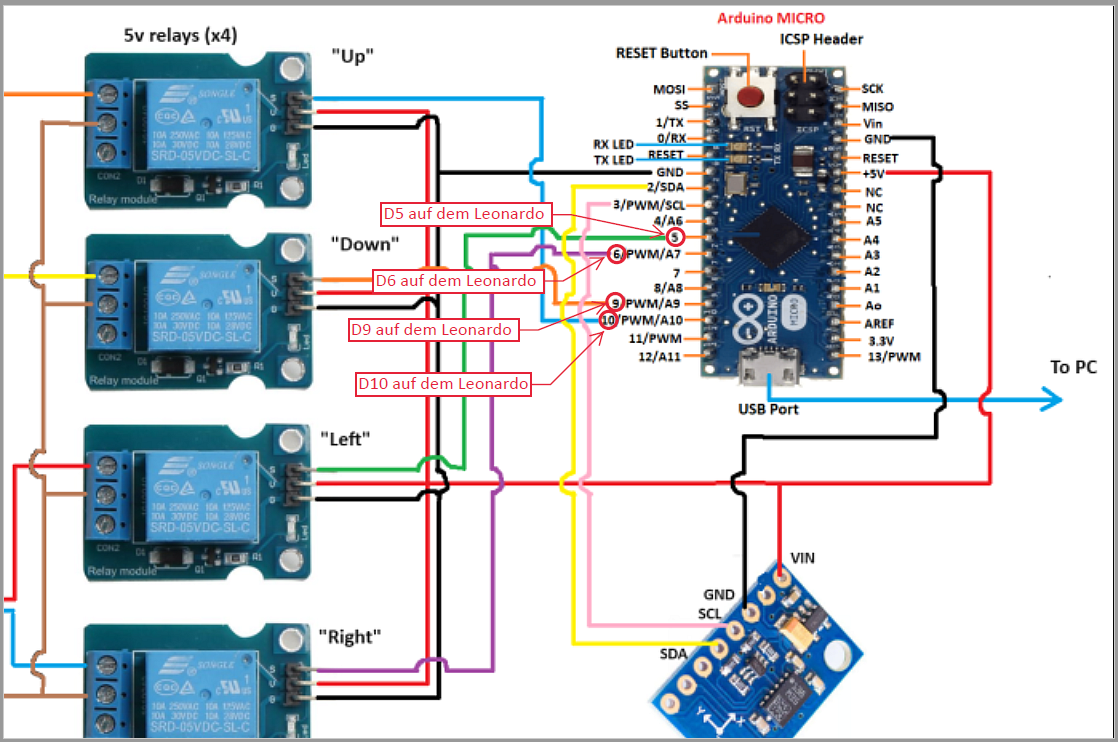
Verdrahtungsschema Arduino Micro mit Relaismodulen
Header ARDUINO MICRO MOSI SS SCK MISO 1/TX 0/RX Vin GND RESET +5V RX LED TX LED NC 2/SDA A5 SCL 3/PWM/A6 A4 5/PWM/A7 A3 D5 auf dem Leonardo 6/PWM/A8 A2 D6 auf dem Leonardo 7/PWM/A9 A1 D9 auf dem Leonardo 8/PWM/A10 Ao 10/PWM 11/A11 AREF 3.3V D10 auf dem Leonardo 13/PWM USB Port To PC GND SCL SDA "Down
in „Allgemeine Grundfragen Sat-Rotoren bei 0°/360° Durchlauf“ · HF, Funk und Felder · · Diagramme
-
PDF
TPN15.1E_LA.pdf
PWM2-B1 3 PWM2-R3 PWM2-G3 PWM2-B3 PWM2-R4 PWM2-G4 PWM2-B4 1 F009 F004 F007 F006 F002 AMBI-TEMP +3V3AL +3V3 GND PWM2-R2 3 PWM2-G2 3 PWM2-B2 3 2014-05-07 TCL5971 715G7035 19792_514.eps 2015-Oct-20 back to
in „Philips 6300 TV Bildfehler "fading"“ · Analoge Elektronik und Schaltungstechnik ·
-
Datei
source.c
1; return (highbyte*256 + lowbyte); } /* --- Ausgabe des pulsweitenmodulierten Signals --- */ void pwm(unsigned char pwm_schwelle) { /* --- Sollwertbegrenzung --- */ if (pwm_schwelle<(128-60)) pwm_schwelle=(128-60); if (pwm_schwelle>(128+60)) pwm_schwelle=(128+60); OCR1AL=pwm_schwelle-1; // ergibt PWM Signal am PD5 OCR1BL=pwm_schwelle+1; // ergibt PWM Singal am PD4 } ///////////////////////////////////////////////////////////////////////////////////////////////////////////////// // read_adc // ///////////////////////////
in „UART Daten empfangen“ · Mikrocontroller und Digitale Elektronik ·
-
PDF
UCN5804.pdf
FOR DC AND BIPOLAR STEPPER MOTORS Dual Full Bridge with Protection & Diagnostics ±500 mA 30 V 3976 PWM Current-Controlled Dual Full Bridge ±650 mA 30 V 3966 PWM Current-Controlled Dual Full Bridge ±650 mA 30 V 3968 PWM Current-Controlled Dual Full Bridge ±750 mA 45 V 2916 PWM Current-Controlled Dual Full Bridge ±750 mA 45 V 2919 PWM Current-Controlled Dual Full Bridge ±750 mA 45 V 6219 PWM Current-Controlled Dual Full Bridge ±800 mA 33 V 3964 PWM Current-Controlled Full Bridge ±1.3 A 50 V 3953 PWM Current-Controlled Dual Full Bridge
in „Welchen einfachen Schrittmotortreiber?“ · Analoge Elektronik und Schaltungstechnik ·
-
PDF
ucn5804b.pdf
FOR DC AND BIPOLAR STEPPER MOTORS Dual Full Bridge with Protection & Diagnostics ±500 mA 30 V 3976 PWM Current-Controlled Dual Full Bridge ±650 mA 30 V 3966 PWM Current-Controlled Dual Full Bridge ±650 mA 30 V 3968 PWM Current-Controlled Dual Full Bridge ±750 mA 45 V 2916 PWM Current-Controlled Dual Full Bridge ±750 mA 45 V 2919 PWM Current-Controlled Dual Full Bridge ±750 mA 45 V 6219 PWM Current-Controlled Dual Full Bridge ±800 mA 33 V 3964 PWM Current-Controlled Full Bridge ±1.3 A 50 V 3953 PWM Current-Controlled Dual Full Bridge
in „Schrittmotoren ansteuern mit UCN5804b“ · Mikrocontroller und Digitale Elektronik ·
-
PDF
UCN5804B.pdf
FOR DC AND BIPOLAR STEPPER MOTORS Dual Full Bridge with Protection & Diagnostics ±500 mA 30 V 3976 PWM Current-Controlled Dual Full Bridge ±650 mA 30 V 3966 PWM Current-Controlled Dual Full Bridge ±650 mA 30 V 3968 PWM Current-Controlled Dual Full Bridge ±750 mA 45 V 2916 PWM Current-Controlled Dual Full Bridge ±750 mA 45 V 2919 PWM Current-Controlled Dual Full Bridge ±750 mA 45 V 6219 PWM Current-Controlled Dual Full Bridge ±800 mA 33 V 3964 PWM Current-Controlled Full Bridge ±1.3 A 50 V 3953 PWM Current-Controlled Dual Full Bridge
in „Schrittmotor mit AT90S4433“ · Mikrocontroller und Digitale Elektronik ·
-
Datei
f2u_tiny45.c
hier PB.2 mit aktivem Pullup) wird gemessen und skaliert auf eine maximale Frequenz (hier 50 Hz) als PWM mit Timer0 an PWM_AUSGANG (PB.0) ausgegeben. Die PWM-Frequenz beträgt 31 kHz und muß mit einem RC-Glied gefiltert werden, um das Gleichspannungssignal zu erhalten: 10 kOhm und 10 µF reichen. Die Frequenzmessung
in „Impulse von Reedkontakt als Spannung anzeigen NE555“ · Mikrocontroller und Digitale Elektronik ·
-
Datei
f2u_tiny45.c
hier PB.2 mit aktivem Pullup) wird gemessen und skaliert auf eine maximale Frequenz (hier 50 Hz) als PWM mit Timer0 an PWM_AUSGANG (PB.0) ausgegeben. Die PWM-Frequenz beträgt 31 kHz und muß mit einem RC-Glied gefiltert werden, um das Gleichspannungssignal zu erhalten: 10 kOhm und 10 µF reichen. Die Frequenzmessung
in „Analoges Fahrrad-Tachymeter mit Dynamo betreiben“ · Analoge Elektronik und Schaltungstechnik ·
-
PDF
hab_80-s.pdf
drift ●● Hermetic package. Time Automotive applications ●● Battery Pack Monitoring ●● Hybrid Vehicles PWM period T Period= THigh + TLow ●● EV and Utility Vehicles. PWM frequency = 1 =125Hz T Period T DutyCycle (% = High ×100 T Period DutyCycle (% = 50%+G×I P with G = Sensitivity (%/A) The PWM period T starts
in „Abfragen von mehreren Stromwandlern (PWM, DutyCycle)“ · Mikrocontroller und Digitale Elektronik ·
-
PDF
doc7593.pdf
correct PWM mode, the compare units allow generation of PWM wave- forms on the OCnx pins. Setting the COMnx1:0 bits to two will produce a non-inverted PWM and an inverted PWM output can be generated by setting
in „Problem mit dem TC4469“ · Mikrocontroller und Digitale Elektronik ·
-
PDF
attiny84.pdf
correct PWM mode, the compare units allow generation of PWM wave- forms on the OC1x pins. Setting the COM1x1:0 bits to two will produce a non-inverted PWM and an inverted PWM output can be generated by setting
in „Attiny 84 ISP?!“ · Mikrocontroller und Digitale Elektronik ·
-
PDF
AVR_ATtiny_24_44_84.pdf
correct PWM mode, the compare units allow generation of PWM wave- forms on the OC1x pins. Setting the COM1x1:0 bits to two will produce a non-inverted PWM and an inverted PWM output can be generated by setting
in „AVR Programm brennen ohne Bootloader“ · Mikrocontroller und Digitale Elektronik ·
-
Datei
ProgrammV2.asm
temp1, (1<<ADEN)|(1<<ADPS2)|(0<<ADPS1)|(1<<ADPS0) out ADCSRA, temp1 ;--------------------------------PWM Initialisierung-------------------------------------- ; PWM initialisieren 14Fast PWM Betrieb ldi temp1, (1<<COM1A1)|(1<<WGM11)|(0<<WGM10) out TCCR1A, temp1 ldi temp1, (1<<WGM13) | (1<<WGM12) | (1<<
in „Analog zu PWM. Fehler im Programm?“ · Mikrocontroller und Digitale Elektronik ·
-
Datei
Master.c
power_reduction = (1<<PRTIM1) | (0<<PRTIM0) | (1<<PRUSI) | (0<<PRADC); //Set the modus of the counter - Set PWM, phase correct timer0_modus = (0<<COM0A1) | (0<<COM0A0) | (1<<COM0B1) | (0<<COM0B0) | (1<<WGM01) | (1<<WGM00); //Set the prescaler of the PWM clock, no pre-sclaer set. Counter (8bit) overflows (1000000
in „ATTINY84A Rechnung in C“ · Mikrocontroller und Digitale Elektronik ·
-
Datei
PDM_2SpgE.ino
/* 2 Spannungsebenen * Pulsdauermodulation * Arduino Micro */ #define F_PWM 62500L //Hz #define PRESCALER 1 #define TIMER_RELOAD ((F_CPU / ( PRESCALER * F_PWM) -1)) //Fast PWM //Variablen volatile uint16_t Frequenz; volatile uint8_t Amplitude; const int8_t Sinus[256] PROGMEM
in „Arduino Micro SPWM“ · Mikrocontroller und Digitale Elektronik ·
-
PDF
Larson_Scanner_Code.pdf
1 //07_Larson Scanner 2 3 //Bei diesem Programm handelt sich es um einen Larson-Scanner mit PWM. 4 //Die Position stellt den hellsten Punkt der 16 LED's dar die umliegenden LED's (+-2) sollen dunkler erscheinen durch PWM. 5 //Die restlichen LED's sollen leicht klimmen aka Night-Rider . 6 //In
in „Larson Scanner mit 2 Schieberegister (Arduino UNO rev3)“ · Projekte & Code ·
-
PDF
7937v130.pdf
the LEDs bright- The PWM control circuitry is connected to the FB pin. Reducing the duty cycle on the PWM signal re- ness as listed below: sults in increased LEDs brightness levels. The LED ¨ A PWM signal on the SHDN pin brightness
in „Was ist das für ein SMD-Bauteil?“ · Mikrocontroller und Digitale Elektronik ·
-
PDF
HT7937_datasheet.pdf
the LEDs bright- The PWM control circuitry is connected to the FB pin. Reducing the duty cycle on the PWM signal re- ness as listed below: sults in increased LEDs brightness levels. The LED ¨ A PWM signal on the SHDN pin brightness
in „LCD Monitor defekt“ · Mikrocontroller und Digitale Elektronik ·
-
PDF
Selbstbau_Impulswahl_auf_Tonwahl_Konverter_20200810h.pdf
mit Rechteck doch funktioniert, bist Du spätestens nach einem Tiefpass 2. Ordnung im Soll. Bei der PWM-Aufbereitung ist der Tiefpass zwingend nötig, folglich bringt ein PWM Sinus da keinen Vorteil der mich von der Tone.h abbringen könnte. Plan B wäre ein HT9200 gewesen. https://www.mikrocontroller.net
in „Anmeldezwang JA oder NEIN Umfrage“ · www.mikrocontroller.net ·