-
PDF
AN734.pdf
FSR bsf SSPCON1,CKP ; Release clock( for transmit and receive) retfie FAST ; Return from interrupt DS00734B-page 14 © 2008 Microchip Technology Inc. AN734 ;---------------------------------------------------------------- ; State 1: I2C write operation, last byte was an address byte ; SSPSTAT bits: S
in „I2C example code“ · Mikrocontroller und Digitale Elektronik ·
-
PDF
58L128.pdf
INPUT GW# 18 REGISTERS CE# ENABLE CE2 REGISTER CE2# 2 OE# FUNCTIONAL BLOCK DIAGRAM 64K x 32/36 16 16 14 16 SA0, SA1, SA ADDRESS REGISTER SA0-SA1 MODE ADV# BINARY Q1 CLK COUNTER SA1' AND LOGIC Q0 CLR SA0' ADSC# ADSP# BWd# BYTE “d” 9 BYTE “d” 9 WRITE REGISTER WRITE DRIVER BYTE “c” 64K x 8 x 4 BWc# BYTE “
in „4GSPS ADC SRAM Speicher“ · Mikrocontroller und Digitale Elektronik ·
-
Datei
AquaDosierung_V1_2.ino
char pause_hour = 0; char pause_min = 0; char pause_day = 0; char pause_month = 0; /*-----[ Zeitmodul DS3231 einlesen und aktivieren )-----*/ void setDS3231time(int second, int minute, int hour, int ndofweek, int dday, int dmonth, int dyear) { Wire.beginTransmission(ADDR_RTCDS3231); Wire.write(0); Wire.write
in „Arduino LCD Backlight auto off“ · Mikrocontroller und Digitale Elektronik ·
-
PDF
B154EW04_VB.pdf
case is connected with signal GND. 6 B154EW04 V.B Page /23 4-2 Interface block diagram Using receiver:DS90CF364(National semiconductor) Corresponding Transmitter:DS90C363,DS90C383(National semiconductor) ( Computer side ) (TFT-LCD side ) DS90C*363 DS90CF364 6 TxIN 0~ 5 RXIN0+(6) RxOUT0~5 6 R0~R5 R0~R5 6
in „Notebookdisplay als "normalen" Bildschirm verwenden“ · PC Hard- und Software ·
-
Datei
BME280.c
Langemann mailto: Manfred.Langemann@t-online.de Begin of project: 09.08.2026 Latest version generated: 14.08.2026 Filename: BME280.c Description: Functions for performing BME280 measurements: - Air Pressure in hPa - Temperature in deg C * 10 - Humidity in %RH It uses the AZ-Delivery GY-BME280 board, bought
in „BME280 Sensor - Code für ATmega328 in C“ · Projekte & Code ·
-
Datei
IC_DIL.txt
4St HEF4066B DIL16 2St. 74LS04N DIL16 1St. 74LS11N DIL16 1St. 74LS14N DIL16 1St. 74LS00N DIL16 4St. 74LS138N DIL16 4St. 74LS85N DIL16 2St. 74LS06 DIL14 1St. 74LS32 DIL14 1St. 74LS30 DIL14 2St. 74LS164 DIL14 1St. 74LS279 DIL 2St 7475N DIP14 1St. 7490N DIP14 1St 7437N DIP14 1St. 74121 DIP 2St 7400 DIP14 (sehr alt) 1St 7403 DIP14 (sehr alt) 2St. 7407 DIL 1St. 7486N DIL 1St. 74155 DIL 1St. 7413 DIL 2St. 74LS244 DIP16 1St. 74F244 DIP16 1St. 74LS245 DIP16 2St. 74LS244 DIP16 1St. 74F244 DIP16 1St. 74LS245
-
PDF
Infineon-IRLML2502-DataSheet-v01_01-EN.pdf
Threshold Voltage Coefficient ––– -3.2 ––– mV/°C gfs Forward Transconductance 5.8 ––– ––– S V DS= 10V, D = 4.0A I Drain-to-Source Leakage Current ––– ––– 1.0 V = 16V, V = 0V DSS μA DS GS ––– ––– 25 V DS= 16V, VGS = 0V, J = 70°C IGSS Gate-to-Source Forward Leakage ––– ––– 100 V GS= 12V nA Gate-to-Source
in „Hilfe bei Bauteilidentifizierung erbeten (MOSFET, SOT23)“ · Offtopic ·
-
PDF
IRLML2502.pdf
Threshold Voltage Coefficient ––– -3.2 ––– mV/°C gfs Forward Transconductance 5.8 ––– ––– S V DS= 10V, D = 4.0A I Drain-to-Source Leakage Current ––– ––– 1.0 V = 16V, V = 0V DSS μA DS GS ––– ––– 25 V DS= 16V, VGS = 0V, J = 70°C IGSS Gate-to-Source Forward Leakage ––– ––– 100 V GS= 12V nA Gate-to-Source
in „Umsetzung eines 5V Output mit ESP32 und AQY Halbleiterrelais“ · Mikrocontroller und Digitale Elektronik ·
-
PDF
Asus_p4p800-e_deluxe.pdf
• • 256MB KINGMAX MPXB62D-38KT3R KINGMAX SS KDL388P4EA-50 • • 512MB KINGMAX MPXC22D-38KT3R KINGMAX DS KDL388P4EA-50(A) • • 512MB KINGMAX MPXC22D-38KT3R KINGMAX DS V58C2256804SAT5B • • • 128MB NANYA NT128D64SH4B1G-5T NANYA SS NT5DS16M16BT-5T • • • 256MB Elixir M2U25664DS88B3G-5T Elixir SS N2DS25680BT-5T • • • 512MB Elixir M2U51264DS8HB3G-5T Elixir DS N2DS25680BT-5T • • • 256MB Kreton N/A Kreton SS VT3225804T-5 • • • 512MB Kreton N/A Kreton DS VT3225804T-5 • • • 256MB Veritech VT400FMV/2561103 Veritech SS VT56DD32M8PC-5 • • • A*
in „passende 2018er PC-Hardware unter Windows XP“ · PC Hard- und Software ·
-
Datei
Bootloader230.a51
DBIT 1 ; new extension bit for disable verify on bootloader dseg at 0x21 ; gloabal vars wValueLo: ds 1 ; 0x21 BootKey: ds 8 ; 0x22 Marker0: ds 1 ; 0x2A rlen: ds 1 ; 0x2B reqlen: ds 1 ; 0x2C cmdbuffer: ds 64 ; 0x2D ds 2 ; 0x6d spare bRequest: ds 1 ; 0x6F SnSum: ds 1 ; 0x70 DescAddr: ds 2 ; 0x71 CAddr: ds 2 ; 0x73 Marker1: ds 1 STACK: xseg at 0 EP0_BUFFER: ds 8 ; 0x0000 the control endpoint ds 4 ; spare EP2_BUFFER: ds 64 ; 0x000C bulk out Response: ds 64 ; 0x004C bulk in cseg at StartAddress ; bootloader
in „uC für 0,20€ CH552 / CH554 von WCH Billig Micro mit USB Funktion, Chip vorstellung“ · Mikrocontroller und Digitale Elektronik ·
-
Datei
Values.txt
18 FT232RL 18 BC337 18 B 18 27p 18 1N4148DO35-10 18 15p 18 15k 17 BC847 17 560 17 47n 17 200k 16 SE14 16 60R 16 470pF 16 22 16 12 Ohm 16 12k 16 10-XX 16 1,0 uF 16 10 nF 16 100nf 15 HDSP-B56Z 15 74164N 15 47p 15 47K 15 470n 15 3k3 15 390 15 18p 15 100u 15 0.47u 14 ZPD 5,1 14 TP06SQ 14 ISP 14 680R 14 4,7n 14 22pf 14 16MHz 13 NC 13 250 13 22uF 13 16Mhz 13 10 13 0.1u 13 0 12 TLC5940-PWPOTV 12 SR104 12 IRFP460 12 IRF540 12 HD-H103 12 BL 12 BD140 12 AMP 12 7-SEG_SA10-21 12 74LS08N 12 47µ 12 4052D 12 35701331
in „[KiCad] Bibliotheksaufbau - Konzeptideen gesucht“ · Platinen ·
-
PDF
ISL88731.PDF
DACS 5 0 = Adds 0mA of input current. 1 = Adds 8192mA of input current, 11004mA max. 13 Not used. 14 Not used. 15 Not used. FN9258 Rev 3.00 Page 14 of 22 June 8, 2011 ISL88731 Charger Timeout Acknowledge). The master will then produce a Stop condition to end the read transaction. The ISL88731 includes
in „Chip gesucht“ · Mikrocontroller und Digitale Elektronik ·
-
PDF
digitalSTROM.pdf
jederzeit verschiedene Einstellungen direkt vor- Für Android: (Erhältlich über »Google Play«) nehmen. • dS Home Control • dS NFC • dS Dashboard Bild 34: Die Digitalstrom-App • dS Listener Quelle: Digitalstrom für mobile iOS-Geräte 22 de – das elektrohandwerk Gelernt ist Gelernt Das sind zum Beispiel die Namen
-
PDF
SP8735.pdf
DOCUMENT IS FOR MAINTENANCE PURPOSES ONLY AND IS NOT RECOMMENDED FOR NEW DESIGNS ADVANCE INFORMATION DS3673-1·1 SP8735 600MHz4 8 (BINARY OUTPUTS) The SP8735 is a 48 ECL counter with binary outputs. In addition, carry outputs are provided in TTL and ECL. The AC coupledinput requiresa600mVp-psignal andtheoutputsare
in „Dezimale Vorteilerkorrektur für Frequenzzähler“ · HF, Funk und Felder ·
-
Datei
DS1820.c
Version : 1.3 Date : 19.11.2006 Author : Florian Hämmerle Displays the temperature value of max 4 ds1820 sensors on a 16x2 intelligent lcd display and in a terminal window on computer by serial communication CHIP: AVR 90S2313 Compiler: Codevision AVR Sensors: DS1820 LCD: Hitachi HD44780 chip or equivalent
in „Temperaturmessung mit AT90S2313 und DS1820“ · Projekte & Code ·
-
PDF
STM8_first_test_of_cubeMX.ioc.pdf
9 VDD Power 10 PA3 * I/O GPIO_Output 11 PB5 I/O I2C_SDA 12 PB4 I/O I2C_SCL 13 PC3 * I/O GPIO_Input 14 PC4 I/O ADC_IN2 15 PC5 * I/O GPIO_Input 16 PC6 I/O TIM1_CH1 17 PC7 I/O TIM1_CH2 18 PD1 I/O SYS_SWIM 19 PD2 I/O ADC_IN3 20 PD3 I/O ADC_IN4 * The pin is affected with an I/O function Page 3 STM8_first_test_of_cubeMX
in „[S] STM8CubeMX“ · Mikrocontroller und Digitale Elektronik ·
-
PDF
Ethernet_Transformer_Datasheet.pdf
0,635) ) m 1 FS23 5 5 1 8 8 17 5 m 0 0 , ( • 0344 5RL 3 ) x 6 2 0 0 , 0 ( x 0,350 m 0 (8,890) 16 15 14 11 10 9 0 0 2 ( 0 0,018 typ 0,050 typ (0,457) (1,270) 1 2 3 6 7 8 Ordering information Order-No.: 538431 DS_FS23_V6.PDF Beck IPC GmbH E-Mail: info@beck-ipc.com © Beck IPC GmbH Grüninger Weg 24 www.beck-ipc.com
in „Ethernet Übertrager“ · Mikrocontroller und Digitale Elektronik ·
-
PDF
BUK100-50GL_1.pdf
voltage V IS0 V; I DM = 1 A; p ≤ 300 s; - - 70 V δ ≤ 0.01 IDSS Zero input voltage drain current V DS= 12 V; V IS0 V - 0.5 10 A IDSS Zero input voltage drain current V DS= 50 V; V IS0 V - 1 20 A I Zero input voltage drain current V = 40 V; V = 0 V; T = 125 ˚C - 10 100 A DSS DS IS j R DS(ON) Drain-source
in „12V/2,5 A Sicher schalten“ · Mikrocontroller und Digitale Elektronik ·
-
PDF
ga1.pdf
( ( 0 0 15.000 0.591) Φ1.600(0.063) . . MAX 1 1 0.380(0.015) 0.550(0.022) 2.540(0.100) Typ AZ431-A 14 of 19 March 2018 Document number: DS36721 Rev. 6 - 2 www.diodes.com © Diodes Incorporated AZ431-A Package Outline Dimensions (Cont. All dimensions in mm.) (3) Package Type: SOT23 0.100(0.004) GAUGE PLANE
-
Datei
hwinfop14s.txt
R: 14 U: i2c-dev D: c 89:14 N: i2c-14 L: 0 E: DEVPATH=/devices/pci0000:00/0000:00:02.0/drm/card0/card0-DP-4/i2c-14/i2c-dev/i2c-14 E: SUBSYSTEM=i2c-dev E: DEVNAME=/dev/i2c-14 E: MAJOR=89 E: MINOR=14 P: /devices
in „Lenovo Thinkpad P14s (Intel) freeze beim Steckerziehen“ · PC Hard- und Software ·
-
PDF
Carlo_Gavazzi__EM540DINAV23XS1X.pdf
association of the phases or the direction of the currents via software control. 07/07/2021 EM540 DS ENG Carlo Gavazzi Controls S.p.2. EM540 Structure A N 1 F 2 B 7 89011 2 F C A D E Fig. 1 Front Area Description A Voltage inputs/Current inputs B Display C LED D Browsing and configuration buttons
in „Wirkleistungsmessung 3-phasig, ca. 200 W“ · Haus & Smart Home ·
-
PDF
sensata-acw4-tcw4-canopen-position-sensor-user-manual.pdf
mode - Stopped mode - Reset of the absolute rotary encoder 4. Communication objects 1000h to 1FFFh (DS 301) .............................................................................14 Object 1010h: Store parameters Object 1011h: Restore Default parameters Object 1800h: 1st Transmit PDO communication
in „Hilfe mit (fehlerhafter?) EDS-Datei“ · Softwareentwicklung ·
-
PDF
HM2302A.PDF
V DS = 20V,D = 2.9A 3 D RDS(ON) 59mΩ @ V =GS5V RDS(ON) 45mΩ @ V =GS5V $▯6+%▯▯ ● High Power and current handing capability ● Lead free product is acquired G 1 2S ● Surface Mount Package Marking and pin Assignment
-
Datei
nrf24l01_drv.c
rf_status_reg); if (!to--) { CE_LOW; RF_PowerUpRx(); return RF_TIMEOUT; } } while ((rf_status_reg.tx_ds == false) && (rf_status_reg.max_rt == false)); CE_LOW; /* Modul ist jetzt im Standby-II Mode, zurückschalten in RX Mode */ RF_PowerUpRx(); /* Keine Antwort? */ if (!rf_status_reg.tx_ds) return RF_NO_ACK
in „EmBitz Debugging Problem mit STM32F103“ · Mikrocontroller und Digitale Elektronik ·
-
Datei
nrf24l01_drv.c
rf_status_reg); if (!to--) { CE_LOW; RF_PowerUpRx(); return RF_TIMEOUT; } } while ((rf_status_reg.tx_ds == false) && (rf_status_reg.max_rt == false)); CE_LOW; /* Modul ist jetzt im Standby-II Mode, zurückschalten in RX Mode */ RF_PowerUpRx(); /* Keine Antwort? */ if (!rf_status_reg.tx_ds) return RF_NO_ACK
in „Kleine Frage zu Makros“ · Mikrocontroller und Digitale Elektronik ·
-
PDF
STM32H7-Disco_full.PDF
PR401PI40 NLoo 1k0 Lo p2 GND 1 R14112 1 R146 2 PI10 P112 PR40 PI40 R1413 R148 PI10 P132 PR40 PI40 2k0 1k0 14 U1U5 15 1 R14152 1 R150 2 PI51 DS Q0 PU51 PI10 P152 PR50 PI50 1PI51 SHCP Q1 PU51 COR14 COR5 1PI51 PU52 PI1014P172 PR501PI50 13 STCP Q2 3 GND PI51 OE Q3 PU53 R1494 R154 1PI51 MR Q4 PU54 PI10 P192 PR50
in „STM32H7-Disco erster Test“ · Mikrocontroller und Digitale Elektronik ·
-
PDF
edison-module_HG_331189.pdf
Edison 70-pin connector part numbers Hirose P/N Mating stack height DigiKey P/N Mouser P/N DF40C-70DS-0.4V(51) 1.5 mm n/a 798-DF40C70DS04V51 DF40C(2.0)-70DS-0.4V(51) 2.0 mm H11908CT-ND (low quantity) 798-DF40C2070DS04V51 H11908TR-ND (tape and reel) DF40HC(3.0)-70DS-0.4V(51) 3.0 mm n/a n/a The Intel®
in „Intel Edison Breakout Board“ · Mikrocontroller und Digitale Elektronik ·
-
Datei
AVR_T_DS18S20.cpp
////////////////////////////////////////////////////////// // // Time-stamp: "25.12.09 22:59 AVR_T_DS18S20.cpp klaus?wachtler.de" // //////////////////////////////////////////////////////////////////////////////// // // Beispiel für Anschluß Temperatursensor DS18S20 (1-wire) an ATMega32 // // Zudem verwendet
in „DS18S20 Temperatur auslesen mit C geht nicht“ · Mikrocontroller und Digitale Elektronik ·
-
PDF
302911.pdf
D15 connected with MCU data bus. 19 D14 20 D13 I/O PS Description 21 D12 1 8-bit Bus: D17 to D10 9-bit Bus: D17 to D9 22 D11 D[17] SCL: Synchronous Clock Input 23 D10 0 D[16] SDI: Serial Data Input D[15] SDO: Serial Data Output 24 D9 Product
in „oled spannungsversorgung“ · Mikrocontroller und Digitale Elektronik ·
-
PDF
HBruecke_TLE5205.pdf
applications Operates at supply voltages up to 40 V P-TO220-7-11 Very low R ; typ. 200 Ω @ 25 °C per switch DS ON Output full short circuit protected Overtemperature protection with hysteresis and diagnosis Short circuit and open load diagnosis with open drain error flag Undervoltage lockout CMOS/TTL compatible
in „FET auswählen“ · Analoge Elektronik und Schaltungstechnik ·
-
PDF
board_schematic2.pdf
DS0# DVSB# DVSA# 13,14 TP13 1 WB_-12V 120 IRQIN0 DS1#/FANIN3 5 DIRJ DVSB# 14 R5%4k7S03 MJMPR254 MJMPR254 MJMPR254 1 121 GP17 DIR# 8 DIRJ 13,14 TP14 1 WB_+12V 122 GP16 STEP# 9 STEPJ STEPJ 13,14 U19 B TP15
in „USB 2.0 Beschaltung“ · Mikrocontroller und Digitale Elektronik ·
-
Datei
RFM70_init.c
0x00000000, 0x00000000, 0x00000000, 0x00000000, 0x00000000, 0x00127300, 0x36B48000, }; const UINT8 Bank1_Reg14[]= { 0x41,0x20,0x08,0x04,0x81,0x20,0xCF,0xF7,0xFE,0xFF,0xFF }; //Bank0 register initialization value const UINT8 Bank0_Reg[][2]={ {0,0x0F},//reflect RX_DR\TX_DS\MAX_RT,Enable CRC ,2byte,POWER UP,PRX
in „Hat jemand Erfahrung mit dem 2,4GHz-Transceiver RFM70?“ · HF, Funk und Felder ·
-
 Bild
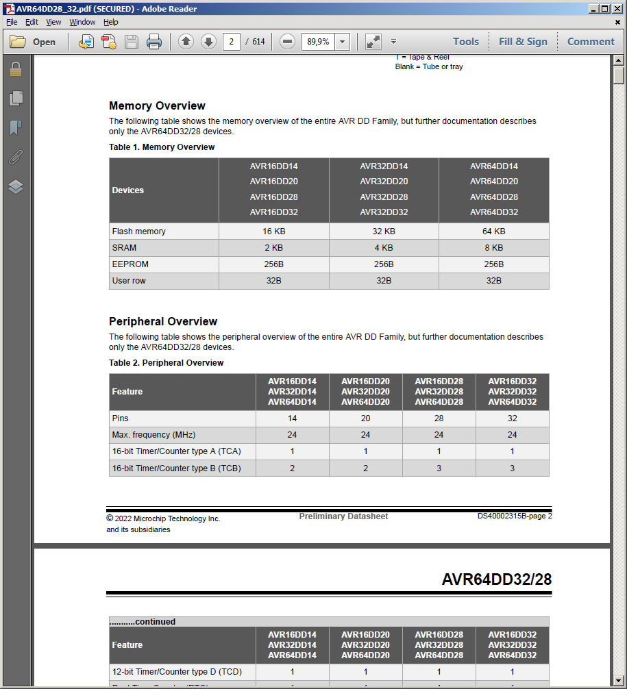
Ausschnitt aus einem Datenblatt von AVR Mikrocontrollern
AVR64DD28_32.pdf (SECURED) - Adobe Reader Memory Overview Table 1. Memory Overview AVR16DD14 AVR32DD14 AVR64DD14 AVR16DD20 AVR32DD20 AVR64DD20 AVR16DD28 AVR32DD28 AVR64DD28 AVR16DD32 AVR32DD32 AVR64DD32 Flash memory 16 KB 32 KB 64 KB SRAM 2 KB 4 KB 8 KB EEPROM 256B 256B 256B User row 32B 32B 32B Peripheral Overview Table 2. Peripheral Overview Feature AVR16DD14 AVR16DD20 AVR16DD28 AVR16DD32 AVR32DD14 AVR32DD20 AVR32DD28 AVR32DD32 AVR64DD14 AVR64DD20 AVR64DD28 AVR64DD32 Pins 14 20 28 32 Max. frequency (MHz) 24 24 24 16-bit Timer/Counter type A (TCA) 1 1 1
in „AVR64DD20 - USART stürzt bei großem Buffer ab“ · Mikrocontroller und Digitale Elektronik · · Screenshots
-
PDF
IP_Protocol_AVR-Xx100.pdf
Bright→Dim→Dark→OffDIM SEL<CR> <- ○ ○ ○ ○ ○ ○ ? Return DIM Status DIM ?<CR> <- ○ ○ ○ ○ ○ ○ Revision FY14V01 4/28/2014 FY14V02 6/8/2014ed X4100/x5200 FY14V03 11/6/201ded X7200 FY14V04 1/8/2015ed commands for Auro-3D Upgrade FY14V05 2/20/201ded commands for X7200A CHINA The command for X7200A is same as X7200. FY14V06 6/30/201vised
in „Mit Raspberry über TCP/IP auf AV-Receiver zugreifen und auf Events reagieren“ · Softwareentwicklung ·
-
Datei
neuro.asm
cl ; because the full deinstallation causes mov ax,0fa02h ; warnings mov dx,5945h int 16h ks1: push ds xor ax,ax mov ds,ax les si,ds:[21h*4] ; get INT 21h handler pop ds mov ax,word ptr es:[si] ; get first two instructions of INT 21h cmp ax,05ebh ; Is it that fucking TBDRIVER ? jne ks2 mov word ptr es
in „Retro Fieber: Z80 oder 68000 ?“ · Mikrocontroller und Digitale Elektronik ·
-
PDF
HINK-E029A01-0629.pdf
......................25 14.2 Definition of contrast ratio.....................................................................26 14.3 Reflection Ratio............................................................................
in „Sammelbestellung elektronische Preisschilder?“ · Markt ·
-
PDF
ATtiny212_412-Errata-and-Clarification-DS40002114B.pdf
BlueSky, BodyCom, CodeGuard, CryptoAuthentication, CryptoAutomotive, CryptoCompanion, CryptoController, dsPICDEM, dsPICDEM.net, Dynamic Average Matching, DAM, ECAN, EtherGREEN, In-Circuit Serial Programming, ICSP, INICnet, Inter-Chip Connectivity, JitterBlocker, KleerNet, KleerNet logo, memBrain, Mindi, MiWi
in „Attiny412 Temperatur intern“ · Mikrocontroller und Digitale Elektronik ·
-
PDF
On_Chip_Debug_Spec_51242a.pdf
mentioned herein are the property of their respective companies. 2001 Microchip Technology Inc. DS51242A On-Chip Debugger Specification DS51242A 2001 Microchip Technology Inc. ON-CHIP DEBUGGER 12 SPECIFICATION Table of Contents Chapter 1. Overview 1.1 Introduction ...............................
in „PIC12F509 hidden features und "High Flash"“ · Mikrocontroller und Digitale Elektronik ·
-
PDF
FQ44N10F.pdf
µA l M VDS = 80 V, C = 150°C -- -- 100 µA O S IGSSF Gate-Body Leakage Current, Forward VGS = 25 V, DS = 0 V -- -- 100 nA F I Gate-Body Leakage Current, Reverse V = -25 V, V = 0 V -- -- -100 nA E GSSR GS DS T On Characteristics V GS(th) Gate Threshold Voltage VDS = VGS, D = 250 µA 2.0 -- 4.0 V R DS(on
in „suche mosfet 100V so-8“ · Analoge Elektronik und Schaltungstechnik ·
-
PDF
NDS355AN.pdf
12. Switching Waveforms . NDS355AN Rev.C Typical Electrical Characteristics (continued) 7 30 S N V DS = 5.0V TJ= -55°C 6 10 100u E ) M I s S 25°C ( 5 N)LI 1 E T 3 DS( ms C 125°C N R N R T4 R 1 10m C C s D N 1 N A 0.3 00m O R 1s s 2 , 0.1 V GS = 4.5V N I SINGLE PULSE DC R 1 0.03 RθJA =See Note1b ,S T
in „nds355/nds356“ · Markt ·
-
Datei
dir.txt
CDC.cpp.d 17.01.2016 16:55 2.432 CDC.cpp.o 17.01.2016 16:56 446.026 core.a 17.01.2016 16:55 3.935 ds18x20.c 17.01.2016 16:55 292 ds18x20.c.d 17.01.2016 16:55 12.456 ds18x20.c.o 17.01.2016 16:55 4.839 ds18x20.h 17.01.2016 16:55 1.022 HardwareSerial.cpp.d 17.01.2016 16:55 27.844 HardwareSerial.cpp.o 17.01.2016
-
PDF
MPVD7N65.pdf
(Min.) DSS PIN Connection Low gate charge: Q =g0nC (Typ.) D Low drain-source On resistance: R DS(on)1.35 Ω (Max.) D 100% avalanche tested RoHS compliant device G Ordering Information G ORDER CODE MARKING PACKING S S MPVD7N65 MPVD7N65 TO-252 TO-252 Absolute maximum ratings (TC=25C unless otherwise
in „Unbekannte Bauelemente“ · Analoge Elektronik und Schaltungstechnik ·
-
Datei
main.lst
this module 11 ;-------------------------------------------------------- 12 .globl _main 13 .globl _l 14 .globl _i 15 .globl _k 16 ;-------------------------------------------------------- 17 ; special function registers 18 ;-------------------------------------------------------- 0004 19 _ReadPort = 0x0004
in „Retro Fieber: Z80 oder 68000 ?“ · Mikrocontroller und Digitale Elektronik ·
-
PDF
drv8825.pdf
-50 -25 0 25 50 75 100 125 V (VMx)V) D003 TA(GC) D004 Figure 4. R vs V Figure 5. R vs Temperature DS(ON) (VMx) DS(ON) 8 Submit Documentation Feedback Copyright © 2010–2014, Texas Instruments Incorporated Product Folder Links: DRV8825 DRV8825 www.ti.com SLVSA73F –APRIL 2010–REVISED JULY 2014 8 Detailed
in „Suche passenden Treiber für Stepper.“ · Mikrocontroller und Digitale Elektronik ·
-
PDF
DS1000Z_Analog.pdf
A0 14 4051_A1 10K 10K 10K 10K 2.5V 4 DAC_TLC274IPWR 1K,±1% A1 15 4051_A2 DAC_VREF 3 DAC VOUT 4 A3 12 4051_A3 1 VREF_BUF 7 DIN 11 S0 A4 1 4051_A4 12COC14 COUDA 2 5 SCLK VDD 8 VCC_5V 19 S1 A5 2 4051_A5 C16 24
in „Analogverstärker für Mikrocontroller Oszilloskop“ · Analoge Elektronik und Schaltungstechnik ·
-
PDF
mic3202.pdf
OPEN H 250 D25% U VCC= 5V C ILED 1A S I L = 47uH 0.5 NO-SWITCHING W 2LED 4LED 6LED 8LED S 0 0% 0.0 6 14 22 30 38 6 14 22 30 38 6 14 22 30 38 INPUT VOLTAGE (V) INPUT VOLTAGE (V) INPUT VOLTAGE (V) V INutdown Current VCC Voltage CS Voltage vs. Input Voltage vs. Input Voltage vs. Input Voltage 0.5 5.050 250
in „MIC3202 : welche empfohlene Schaltung ist geeignet?“ · Mikrocontroller und Digitale Elektronik ·
-
PDF
AN50005.pdf
characteristics: V GS(th) Symbol Parameter Conditions Min Typ Max Unit VGS(th) gate-source threshold ID= 1 mA; V DS=V GS; Tj= 25 °C 2.4 3 3.6 V voltage ID= 1 mA; V DS=V GS; Tj= 175 °C 1 - - V ID= 1 mA; V DS=V GS; Tj= -55 °C - - 4.3 V The total spread, as per data sheet, is ∆V = 1.2 V or ∆V = ± 20 %. The SPICE model
in „N-Canal MOSFET Modul“ · Analoge Elektronik und Schaltungstechnik ·
-
Datei
PLC-LOX-300-13-12-2019Multibus-2.ino
/* UDP syntax: signals: DS18B20 1wire sensor packet: rail1 1w2 2864fc3008082 temp 25.44 DS2438 1wire sensor packet: rail1 1w2 2612c3102004f 25.44 1.23 0.12 Sensor detected (after start): rail1 1w2 2864fc3008082 detected Sensor
in „1 Wire auf 2 GPIO pins“ · Mikrocontroller und Digitale Elektronik ·
-
PDF
APT34F100B2_L_D-1593638.pdf
10 0 5 10 15 20 25 0 200 400 600 800 1000 I , DRAIN CURRENT (A) V , DRAIN-TO-SOURCE VOLTAGE (V) D DS Figure 5, Gain vs Drain Current Figure 6, Capacitance vs Drain-to-Source Voltage 16 140 D = 18A ) ( 14 A 120 E ( A N T 12 E 100 O VDS= 200V R V 10 U E C C VDS= 500V I 80 R 8 A TJ= 25°C O R - D 60 O 6
in „SMA SB4200TL-MS Reparatur“ · Analoge Elektronik und Schaltungstechnik ·
-
PDF
SDA5243.PDF
on page search time characters ROW 7 1 24 8 0 1 2 3 4 5 6 7 8 9 10 MAIN PAGE DISPLAY AREA 11 12 13 14 15 16 17 18 19 20 21 22 23 this row always free for status 24 10 14 25 E 10 bytes for received 14 bytes free 1 page information for use by C 4 5 11/20 SDA5243 - SDA5243/H Table 1 : Row25 receivedcontrol
in „Externer Videotextdecoder“ · Mikrocontroller und Digitale Elektronik ·