-
Datei
ws2812.h
/* * Copyright 2012 Alan Burlison, alan@bleaklow.com. All rights reserved. * Use is subject to license terms. */ /* * WS2811 RGB LED driver. */ #ifndef WS2811_h #define WS2811_h // RGB value structure. typedef struct __attribute__ ((__packed__)) { uint8_t r; uint8_t g; uint8_t b; } RGB_t; #ifndef ARRAYLEN #define ARRAYLEN(A) (sizeof(A) / sizeof(A[0])) #endif /* * Inline asm macro to output 24-bit RGB value in (G,R,B) order, MSBit first. * 0 bits are 250ns hi, 1000ns lo, 1 bits are 1000ns hi, 250ns lo. * r18 = red byte to be output * r19 = green byte to be output * r20 = blue byte to be output * r26
in „Portierung ASM“ · Mikrocontroller und Digitale Elektronik ·
-
Datei
ws2812.s
/* * ws2812.s * * Created: 12.12.2012 01:09:32 * Author: adrock */ #include <avr/io.h> #include "asmdefs.h" #define F_OUT 800000 #define F_CPU 16000000 #define CNT_TOTAL ((F_CPU/F_OUT)-1) #define CNT_LOW ((F_CPU
in „Serielle Ansteuerung / Protokoll WS2812 RGB LED“ · Mikrocontroller und Digitale Elektronik ·
-
Datei
ws2812.c
#include <avr/interrupt.h> #include <stdbool.h> #include "ws2812_config.h" #include "ws2812.h" static bool _stripeModeChangeRequest; static bool _stripeDecoChangeRequest; static uint16_t _numOfPixel; static uint8_t _dataPin; static uint8_t _dataPort; void WS2818
in „WS2812b LED-streifen aktualisiert sich erst nach zweitem aufruf“ · Mikrocontroller und Digitale Elektronik ·
-
Datei
ws2812.h
#ifndef WS2818_H_ #define WS2818_H_ #include <stdint.h> #include <stdbool.h> #include "ws2812_config.h" void WS2818(volatile uint8_t* ddr, uint8_t ddrNewSate, volatile uint8_t* port, uint8_t portNewState, uint8_t dataPin, uint8_t totalNumOfLed); void setPixelColor(uint8_t numOfLed, uint8_t
in „WS2812b LED-streifen aktualisiert sich erst nach zweitem aufruf“ · Mikrocontroller und Digitale Elektronik ·
-
Datei
ws2812.h
// write GRB data to WS2812 LED string void ws2812_write(uint8_t *p_data, uint16_t cnt, volatile uint8_t *port, uint8_t mask);
in „Frage zu IR-Remote+LED-Strips an AVR“ · Mikrocontroller und Digitale Elektronik ·
-
Datei
ws2812.ino
<avr/power.h> #endif int i=0; #define PIN 9 // Hier wird angegeben, an welchem digitalen Pin die WS2812 LEDs bzw. NeoPixel angeschlossen sind #define NUMPIXELS 40 // Hier wird die Anzahl der angeschlossenen WS2812 LEDs bzw. NeoPixel angegeben Adafruit_NeoPixel pixels = Adafruit_NeoPixel(NUMPIXELS, PIN
in „LED Uhr mit RTC braucht Taster“ · Mikrocontroller und Digitale Elektronik ·
-
Datei
ws2812.ino
<avr/power.h> #endif int i=0; #define PIN 9 // Hier wird angegeben, an welchem digitalen Pin die WS2812 LEDs bzw. NeoPixel angeschlossen sind #define NUMPIXELS 40 // Hier wird die Anzahl der angeschlossenen WS2812 LEDs bzw. NeoPixel angegeben Adafruit_NeoPixel pixels = Adafruit_NeoPixel(NUMPIXELS, PIN
in „LED Uhr mit RTC braucht Taster“ · Mikrocontroller und Digitale Elektronik ·
-
Datei
WS2812.c
1; DDRB|=_BV(ws2812_pin); uint16_t i; for(i=MAXPIX; i>0; i--) { led[i-1].r=0;led[i-1].g=0;led[i-1].b=0; } DDRD &= ~((1<<PIND2)|(1<<PIND3)|(1<<PIND4)); //d2 d3 d4 PORTD |= (1<<PIND2)|(1<<PIND3)|(1<<PIND4); // Pull ups
in „Kann mit Light WS2812 nicht mehr als 128 LEDs ansteuern“ · Mikrocontroller und Digitale Elektronik ·
-
 Bild
Bild
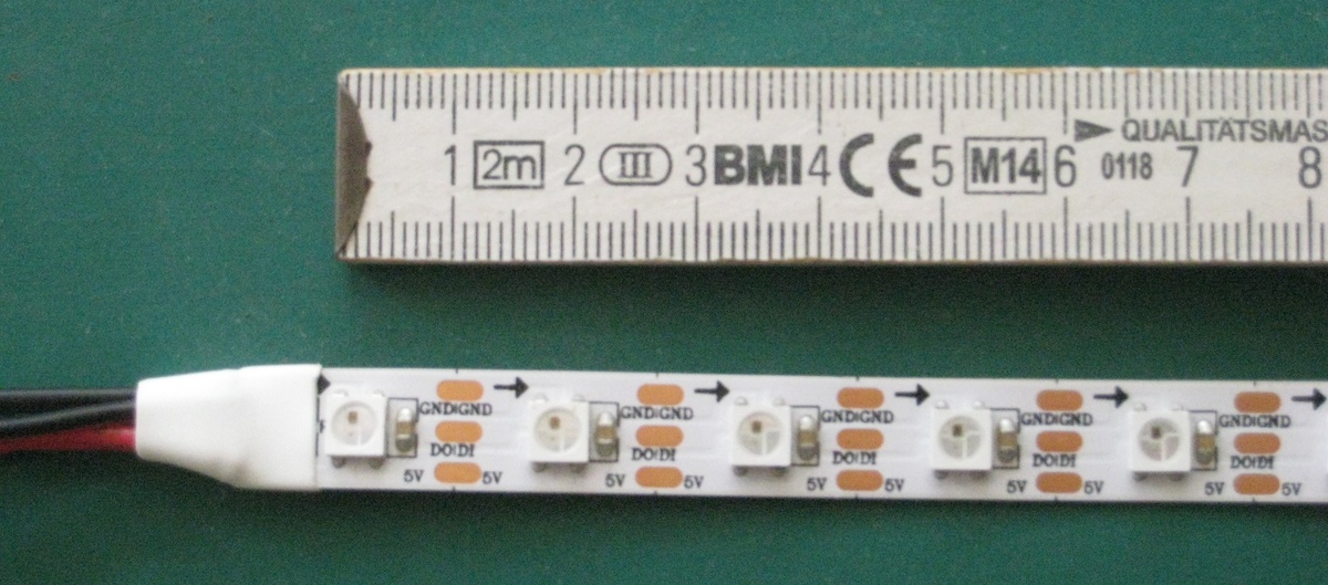
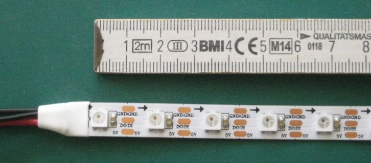
LED-Streifen mit Lineal
1 2m 2 III 3 BMI 4 CE 5 M14 6 0118 7 8 GND GND GND DO DI DO DI DO DI DO DI DO DI 5V 5V 5V
in „[V] LED-Stripes: RGB WS2812 bzw. weiß, jeweils 60 LED/m“ · Markt · · Fotos
-
Datei
putty.txt
button_init... timer2_init... wpsbutton_init... Version: 2.9.5 Hardware: STM32F103 Display: WC12h LEDs: WS2812 GRB Welcome to WordClock Logger! ---------------------------- irmp_init... power_init... power_init() called power_on... switching power on delay_init... board_led_init... button_init... timer2_init... wpsbutton_init... Version: 2.9.5 Hardware: STM32F103 Display: WC12h LEDs: WS2812 GRB rtc is online eeprom is online ws2812: no external pullup detected eeprom is online current eeprom version: 0x00020900 reading ir codes from eeprom DFPLAYER LOGGER ESP8266 LOGGER read rtc: Tu 2019
-
Datei
3-farben-fader.bas
'3-Farben-fader mit WS2812b $regfile = "attiny13a.dat" $crystal = 9600000 $hwstack = 16 $swstack = 16 $framesize = 7 $lib "Rainbow.lib" 'implementierung $external Ws2812b 'Driver Declare sub BOW_INIT() Declare Sub Bow_reset() Declare Sub Bow_clear(byval Set_direct As Byte) Declare sub BOW_Select(Bylabel WS2812b_Channel as Word) Declare Sub Bow_setcolor(byval Lednr As Word , Byval Color As Long , Byval Set_direct As Byte) Const Send = 1 Const Nosend = 0 Const Nosettablecolor = 1 Const Noswap = 1 Const Norotate
in „3x LED-PWM-Faden“ · Mikrocontroller und Digitale Elektronik ·
-
PDF
Anleitung-Wort-Uhr.pdf
UHR Version 2.2.0 Pegelanpassung Der ESP arbeitet intern mit einer Betriebsspannung von 3,3V. Die WS2812(B) Streifen arbeiten dagegen mit 5V. Dies erfordert eine Pegelanpassung, damit die digitalen Signale fehlerfrei zu den Stripes übertragen warden können. Ohne Anpassung kann es auch funktionieren, muss
in „Wortuhr Dioden Multiplex entstören“ · Analoge Elektronik und Schaltungstechnik ·
-
Datei
main.c
XTAL_FREQ 32000000 #include <XC.h> #include <stdio.h> #include <stdlib.h> #include <stdint.h> #include "WS2812.h" void main(void) { unsigned char rgb_data[]={0xFF,0x00,0x00, 0x00,0xFF,0x00 ,0x00,0x00,0xFF,}; int angle; OSCCONbits.SPLLEN=1; // 4x PLL Is enabled OSCCONbits.IRCF=0b1110; // 8 MHz or 32 MHz HF OSCCONbits.SCS
in „[ASM & C] PIC12/PIC18/PIC24 WS2812 SPI Library“ · Projekte & Code ·
-
Datei
main.c
16MHz */ #include <util/delay.h> #include <avr/io.h> #include <avr/interrupt.h> #include "light_ws2812.h" #define MAXPIX 4 #define COLORLENGTH (50) #define FADE (256/COLORLENGTH) struct cRGB colors[8]; struct cRGB led[MAXPIX]; int main(void) { uint8_t j = 1; uint8_t k = 1; DDRB|=_BV(ws2812_pin); uint8
in „Neopixel Attiny85 Makefile Probleme“ · Mikrocontroller und Digitale Elektronik ·
-
Datei
Rainbow.c
16MHz */ #include <util/delay.h> #include <avr/io.h> #include <avr/interrupt.h> #include "light_ws2812.h" #define MAXPIX 30 #define COLORLENGTH MAXPIX/2 #define FADE 256/COLORLENGTH struct cRGB colors[8]; struct cRGB led[MAXPIX]; int main(void) { uint8_t j = 1; uint8_t k = 1; DDRB|=_BV(ws2812_pin);
in „Kann mit Light WS2812 nicht mehr als 128 LEDs ansteuern“ · Mikrocontroller und Digitale Elektronik ·
-
Datei
Lichterkette.c
eeprom.h> #include <avr/io.h> #define EESIZE (1+E2END) #include "Lichterkette.h" #include "light_ws2812.h" #include "ws2812_config.h" typedef struct { const uint8_t numLED; const uint8_t colorWhiteR; const uint8_t colorWhiteG; const uint8_t colorWhiteB; const uint8_t colorOrangeR; const uint8_t colorOrangeG
in „Deadlock in Übersetzungsdurchgang“ · Mikrocontroller und Digitale Elektronik ·
-
Datei
Mit_MS.ino
HAS ONLY GOT THE ADUIO VISUALIZER MODE USING THE MSGEQ7 FOR OTHER MODES SEE THE "RGBStripe_Control_WS2812.ino SKETCH **/ #define USES_POTENTIOMETER 0 // SET THIS TO "1" IF YOU ARE USING POTENTIOMETER FOR BRIGHTNESS CONTROL! #define POT_BRIGHTNESS A2 #define LED_DATA 6 #define NUM_LEDS 300 #define BRIGHTNESS
in „MSGEQ7 zeigt durchgängig einen Wert unabhängig vom Audiosignal an“ · Mikrocontroller und Digitale Elektronik ·
-
Datei
pwm_mpp.ino
#include "WS2812.h" #define numleds 2 uint8_t pixel[numleds*3]; #define PWM_CT1_B 10 //OC1B #define PWM_CT2_B 3 //OC2B #define Vout A1 #define Vin A0 #define maxpwm 4*248 #define minpwm 0 float V_set_in = 17.0; float
in „Hab meinen MPP(T) akkulader probiert :)“ · Mikrocontroller und Digitale Elektronik ·
-
Datei
main.cpp
, active-low. * LED_TYPE 1 -> SuperMini Plus/V2: addressable WS2812B NeoPixel on GPIO8. * */ #include <Arduino.h> #include <NimBLEDevice.h> #ifndef LED_TYPE #define LED_TYPE 0 #endif #if LED_TYPE == 1 #include <FastLED.h> #endif // ---------------------------------
-
Datei
led_modes.c
05.05.2016 23:25:26 * Author: Hannes */ #include <math.h> #include <stdlib.h> #include "includes/light_ws2812.h" #include "config.h" #include "led_modes.h" #define MAX 255 #define RESOLUTION 64 //number of steps to increment the brightness value #define NOF_COLORS 14 #define NOF_MODES (NOF_COLORS + 3) struct
in „Code zu groß für AtTiny45“ · Mikrocontroller und Digitale Elektronik ·
-
Datei
rainbow.c
avr/io.h> #include <avr/eeprom.h> #include <stdlib.h> #include <avr/interrupt.h> #include "light_ws2812.h" #include "irmpconfig.h" #include "irmp.h" //defines LEDs / Programme #define MAXPIX 106 #define COLORLENGTH MAXPIX/2 #define FADE 256/COLORLENGTH #define P_Nothing 0 #define P_ColorPix 1 #define
in „Lightweight WS2811/WS2812 Library“ · Mikrocontroller und Digitale Elektronik ·
-
PDF
Schematic_SIMInterface-Base_Schaltplan_20190313164157.pdf
Connector 17 A1 GPA4 26 12 28 1 MISO +5 2 +5V R9 A2 GPA5 27 11 27 Solder Jumper to run 1K GPA6 10 26 WS2812b with 5V USB 3 4 18 RESET GPA7 28 9 25 power (only in special cases) SCK MOSI 8 24 5 6 20 INTA 7 23 RESET GND 19 INTB GPB0 1 6 22 2 14 GPB1 3 5 21 11 NC GPB2 4 4 20 NC GPB3 3 19 DSP-NEXTION GPB4 5
in „ATMEGA32U4 Schaltplan“ · Mikrocontroller und Digitale Elektronik ·
-
PDF
Schematic_ATMEGA_CaN_L298_2020-04-23_23-39-20.pdf
1 32 L298_IN4 R4 B L298_ENB 2(PCINT19/OC2B/INT1)PD3 PD2(INT0/PCINT18)31 TX 10K ABSTANDSENSOR C2 WS2812_LED 3(PCINT20/XCK/T0)PD4 PD1(TXD/PCINT17) 30 RESET Header-Male-2.54_2x5 22pF GND 4GND PD0(RXD/PCINT16) 29 RX 5V 1 2 SCL 5V 5VCC PC6(RESET#/PCINT14) 28 3 1 GND 3 4 SDA 3 2 GND 6GND PC5(ADC5/SCL/PCINT13
in „atmega328 - arduino bootloader flashen - doppelt belegte Pins“ · Platinen ·
-
 Bild
Bild
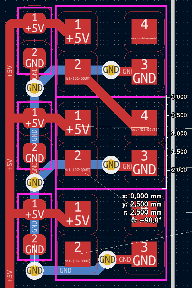
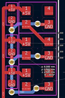
CAD-Ansicht eines Leiterplatten-Layouts
1 +5V 2 GND 3 GND 4 1 +5V 2 GND 3 GND 4 1 +5V 2 GND 3 GND 4 1 +5V 2 GND 3 GND 4 GND Net-(D1-DOUT) GND Net-(D2-DOUT) GND Net-(D3-DOUT) GND x: 0,000 mm y: 2,500 mm r: 2,500 mm $\theta$: -90,0°
in „Suche mini-kleine PCB mit WS2812-kompatiblen LEDs“ · Mikrocontroller und Digitale Elektronik · · Layouts
-
Datei
ws2812test.c
/* * ws2812test.c * * Created: 12.12.2012 00:02:22 * Author: adrock */ #define F_CPU 16000000 #include <avr/io.h> #include <util/delay.h> extern void WS_init(void); extern void WS_put(uint8_t *D, uint16_t Num)
in „Serielle Ansteuerung / Protokoll WS2812 RGB LED“ · Mikrocontroller und Digitale Elektronik ·
-
Datei
Ws2812Spi.c
Author: Thomas */ #include <stdbool.h> #include "sam.h" #include "clocks.h" #include "IO.h" #include "Ws2812Spi.h" #define RAM_FUNC __attribute__ ((long_call, section (".ramfunc"))) #define ISR(func) void func(void) // Cortex M Interrupt handlers can be programmed as normal C functions // Pattern low 1000
in „ATSAM WS2812B?“ · Mikrocontroller und Digitale Elektronik ·
-
Datei
WS2812_Display.ino
#include <CharacterEncoding.h> #include <ShiftDisplay.h> #include <Adafruit_NeoPixel.h> #include <RTClib.h> #include <Wire.h> #include <boarddefs.h> #include <IRremote.h> #include <IRremoteInt.h> #include <ir_Lego_PF_BitStreamEncoder.h> #define PIXEL_PIN 9 // Digital IO pin connected to the NeoPixels. #define PIXEL_COUNT 60 // Parameter 1 = number of pixels in strip, neopixel stick has 8 // Parameter 2 = pin number (most are valid) // Parameter 3 = pixel type flags, add together as needed: // NEO_RGB Pixels are wired for RGB bitstream // NEO_GRB Pixels are wired for GRB bitstream, correct for neopixel
in „WS2811 und 74HC595 Zusammen an Arduino steuren“ · Mikrocontroller und Digitale Elektronik ·
-
Datei
UhrWS2812.ino
/** * NeoClock * * Clock using 60 WS2812B/Neopixel LEDs and DS3231 RTC * * Libraries needed: * * Adafruit NeoPixel (Library Manager) - Phil Burgess / Paint Your Dragon for Adafruit Industries - LGPL3 * * Rtc by Makuna (Library Manager) -
in „LED Uhr mit RTC braucht Taster“ · Mikrocontroller und Digitale Elektronik ·
-
PDF
kurzdatenblatt_ws2812.pdf
WS2812 Oktober 2012, Copyright © KT-Elektronic 1 sk
in „Touch bauen, suche günstigere alternativen“ · Mikrocontroller und Digitale Elektronik ·
-
 Bild
Bild
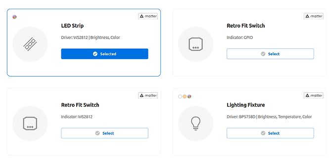
Benutzeroberfläche für Matter-Gerätekonfiguration
matter LED Strip Driver: WS2812 | Brightness, Color Selected Retro Fit Switch Indicator: GPIO Select matter Retro Fit Switch Indicator: WS2812 Select matter Lighting Fixture Driver: BP5758D | Brightness, Temperature, Color Select
in „Neues RTL-SDR-Dongle, Matter-Gerätegenerator von ESP32 und andere Funknachrichten“ · HF, Funk und Felder · · Screenshots
-
 Bild
Bild
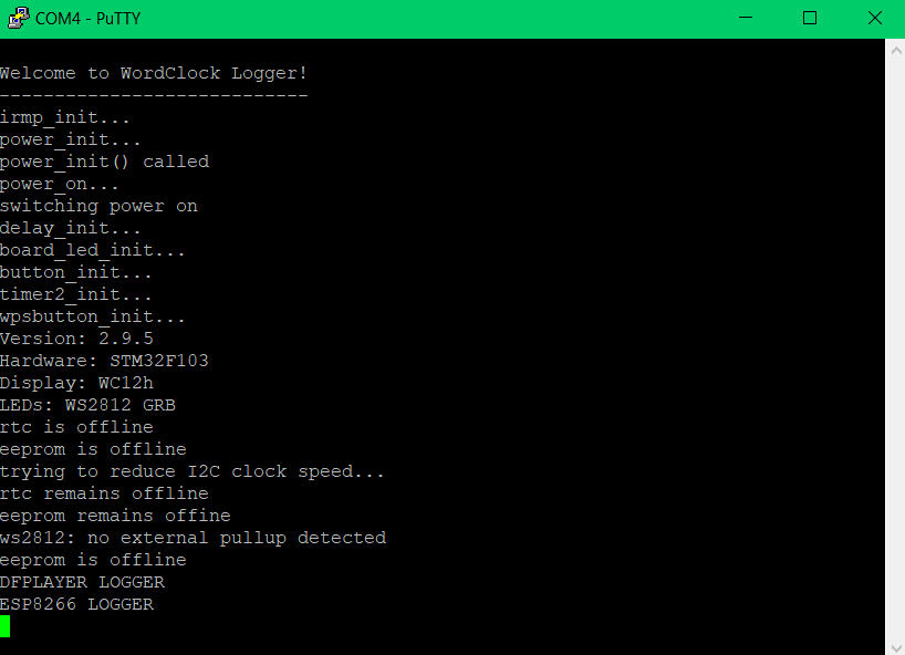
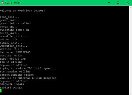
PuTTY Terminal-Ausgabe eines Mikrocontroller-Loggers
button_init... timer2_init... wpsbutton_init... Version: 2.9.5 Hardware: STM32F103 Display: WC12h LEDs: WS2812 GRB rtc is offline eeprom is offline trying to reduce I2C clock speed... rtc remains offline eeprom remains offline ws2812: no external pullup detected eeprom is offline DFPLAYER LOGGER ESP8266 LOGGER
in „WordClock mit WS2812“ · Projekte & Code · · Screenshots
-
 Bild
Bild
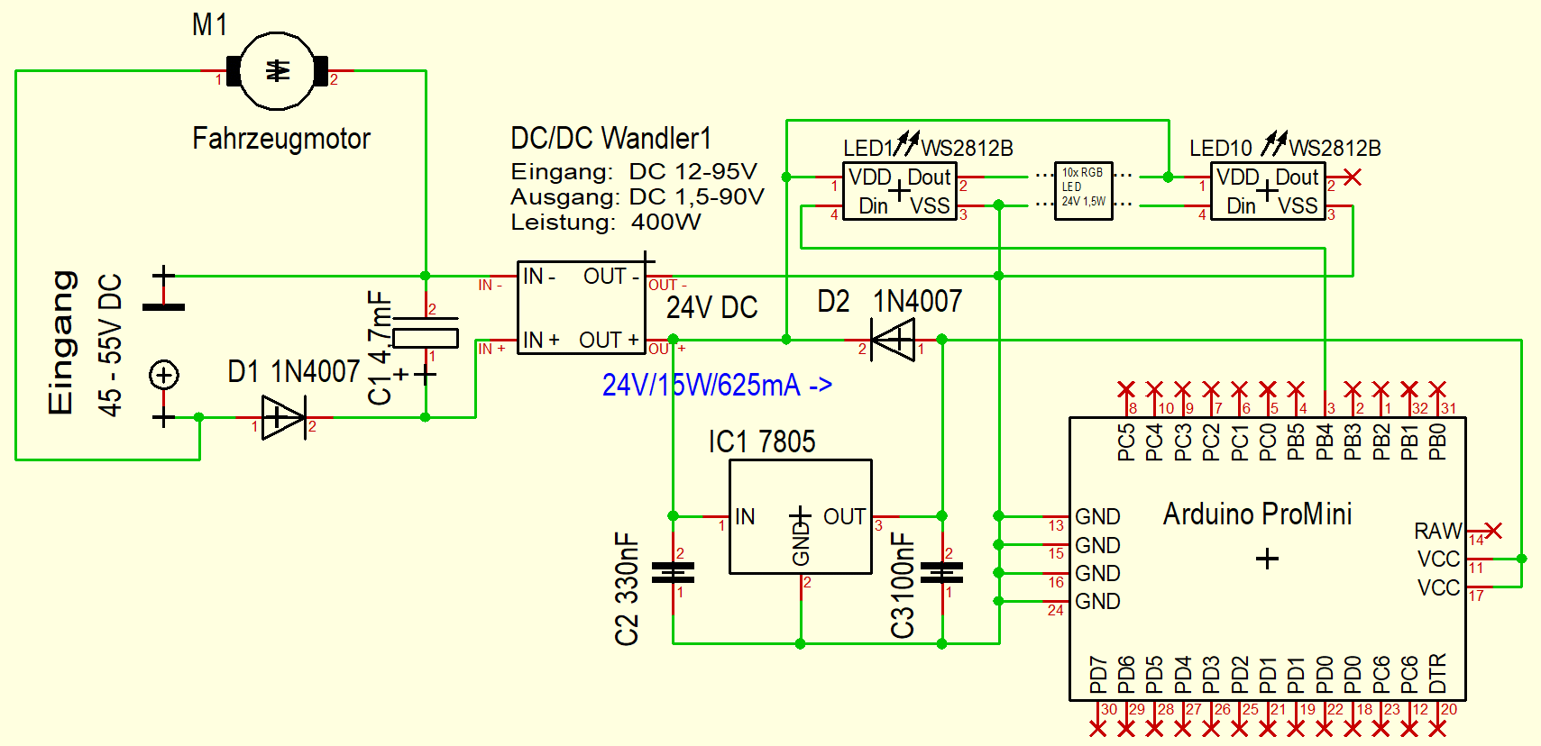
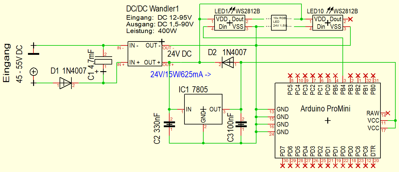
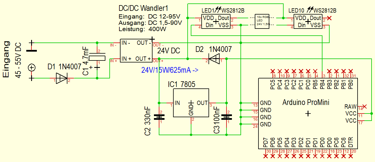
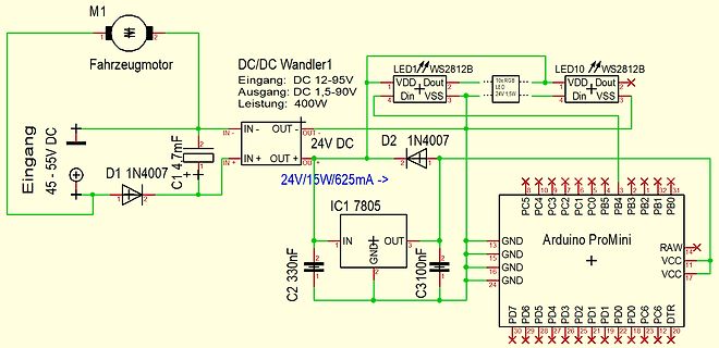
Schaltplan mit DC/DC-Wandler, Motor und Arduino ProMini
M1 Fahrzeugmotor, DC/DC Wandler1, Eingang: DC 12-95V, Ausgang: DC 1,5-90V, Leistung: 400W, LED1 WS2812B, LED10 WS2812B, 24V 1,5W, Eingang 45-55V DC, D1 1N407, C1 4,7mF, 24V/15W/625mA, D2 1N407, IC1 7805, C2 330nF, C3 100nF, Arduino ProMini, PC5 bis PC0, PB5 bis PB1, PB0, RAW, VCC, DDR, DT, PD0 bis PD7
in „DCDC Wandler sterben - Schutzmaßnahmen?“ · Analoge Elektronik und Schaltungstechnik · · Schaltpläne
-
Datei
log.txt
button_init... timer2_init... wpsbutton_init... Version: 2.9.4 Hardware: STM32F103 Display: WC12h LEDs: WS2812 GRB rtc is online eeprom is online ws2812: external pullup detected eeprom is online current eeprom version: 0x00020900 reading ir codes from eeprom DFPLAYER LOGGER ESP8266 LOGGER read rtc: Su 2000
-
PDF
Blockdiagramm.pdf
Heartbeat Heartbeat AREF PC7:0 PF0 LCD Atmega128 DRV5033 PA7:0 I²C MAX520 Pinheader LM4040 + Buffer WS2812 PG0 PB7:0 CAT5259 PG4 ADS7828 RV4162 Backup Battery ICSP M24C64 JTAG PF7:0 AREF PG4 RS232/UART UART0 I²C MAX520 LM4040 + MAX3232 Buffer Atmega128L PCF8563 Backup Battery PA7:0 M24C64 EC11 Taster PC7:0 LCD SPI Heartbeat PG1 WS2812 PG0 ADS7844
in „Dev-Kit machen?“ · Mikrocontroller und Digitale Elektronik ·
-
Datei
Logfile.txt
button_init... timer2_init... wpsbutton_init... Version: 2.9.5 Hardware: STM32F103 Display: WC12h LEDs: WS2812 GRB rtc is online eeprom is online ws2812: external pullup detected eeprom is online current eeprom version: 0x00020900 reading ir codes from eeprom DFPLAYER LOGGER ESP8266 LOGGER read rtc: Su 2000
-
 Bild
Bild
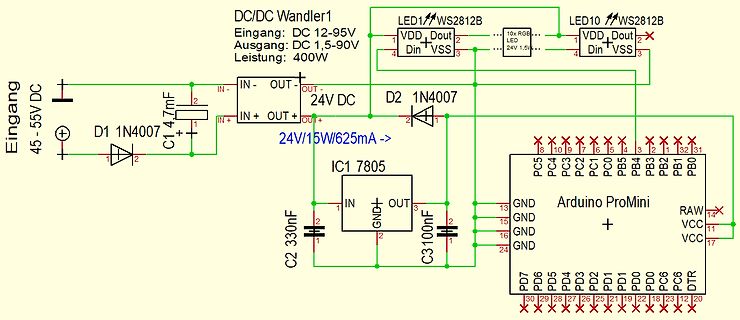
Schaltplan mit Arduino ProMini und DC/DC Wandler
DC/DC Wandler1 Eingang: DC 12-95V Ausgang: DC 1,5-90V Leistung: 400W LED1 WS2812B LED10 WS2812B VDD Dout VSS Din 24V 1,5V Eingang 45-55V DC D1 1N4007 C1 4,7mF IN- OUT- OUT+ IN+ OUT+ 24V DC D2 1N4007 IC1 7805 24V/15W/625mA -> C2 330nF C3 100nF IN GND OUT GND GND GND Arduino ProMini
in „DCDC Wandler sterben - Schutzmaßnahmen?“ · Analoge Elektronik und Schaltungstechnik · · Schaltpläne
-
 Bild
Bild
Schaltplan mit DC/DC-Wandler, Arduino ProMini und LEDs
DC/DC Wandler1 Eingang: DC 12-95V Ausgang: DC 1,5-90V Leistung: 400W LED1 WS2812B LED10 WS2812B 24V 1,5W VDD Dout Din VSS Eingang 45-55V DC D1 1N4007 C1 4,7mF IN- OUT- 24V DC IN+ OUT+ D2 1N4007 24V/15W/625mA -> IC1 7805 IN GND OUT C2 330nF C3 100nF Arduino ProMini GND GND GND RAW
in „DCDC Wandler sterben - Schutzmaßnahmen?“ · Analoge Elektronik und Schaltungstechnik · · Schaltpläne
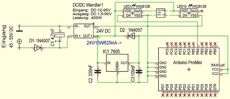
-
Datei
PuTTY_log.txt
button_init... timer2_init... wpsbutton_init... Version: 2.9.1 Hardware: STM32F103 Display: WC24h LEDs: WS2812 GRB rtc is online eeprom is online ws2812: no external pullup detected eeprom is online current eeprom version: 0x00020900 reading ir codes from eeprom DFPLAYER LOGGER ESP8266 LOGGER read rtc: We 2018
-
PDF
Beschreibung_Steuerungssoftware_und_Platinenlayout.pdf
voneinander abhängiges Bewegungsschema vorwärts-rückwärts-Drehung rechts-Drehung links - Steuern von einem WS2812B RGB LED Ring mit 24-32 LEDs - Bedienung über Balkenmenu auf SH1106-OLED-Display 128 x 64 Pixel - Menu-Steuerung über Drehgeber - Menu viersprachig (DE, EN, FR, ES) Alle Einstellungen bei Veränderung
in „Unterstützung gesucht, Micropython & Platinenlayout“ · Markt ·
-
Datei
SK6812.cpp
------ Note. This library has only been tested on the SK6812 LED. It may not work with the older WS2812 or other types of addressable RGB LED, becuase it relies on a division multiple of the 72Mhz clock frequence on the STM32 SPI to generate the correct width T0H pulse, of 400ns +/- 150nS SPI DIV32 gives
in „STM32 Bluepill -> SK6812 (auf Basis von WS2812B Lib)“ · Projekte & Code ·
-
Datei
log.txt
button_init... timer2_init... wpsbutton_init... Version: 2.9.4 Hardware: STM32F103 Display: WC12h LEDs: WS2812 GRB rtc is online eeprom is online ws2812: external pullup detected eeprom is online current eeprom version: 0x00020900 reading ir codes from eeprom DFPLAYER LOGGER ESP8266 LOGGER read rtc: Fr 2019
-
Datei
ws2812_test2.c
/* ------------------------------------------------------- ws2812_test.c Programm zum Ansprechen von WS2812 LED's MCU : STM8S103F3 Takt : interner Takt 16 MHz 28.04.2017 R. Seelig ------------------------------------------------------ */ /* ######################
in „SDCC und struct“ · Mikrocontroller und Digitale Elektronik ·
-
Datei
ws6812_test_zwo.c
#include <util/delay.h> #include <avr/io.h> #include <avr/interrupt.h> #include "light_ws2812.h" #define F_CPU 8000000UL #define ANZAHL_SPALTEN 24 #define ANZAHL_ZEILEN 24 #define ANZAHL_LEDS (ANZAHL_SPALTEN * ANZAHL_ZEILEN) #define UP 1 #define DOWN 0 struct cRGBW led[ANZAHL_LEDS]; uint16_
in „LED-Matrix mit light_ws2812-library; Ansteuerungsgeschwindigkeit“ · Mikrocontroller und Digitale Elektronik ·
-
Datei
main12.asm
LED3 Magenta movwf rgb_byte+6 movlw 0xFF movwf rgb_byte+7 movlw 0xFF movwf rgb_byte+8 call transmit_WS2812 goto $ ;*******************************************************************************; transmit_WS2812 movlw high(rgb_byte) movwf FSR0H movlw low(rgb_byte) movwf FSR0L BANKSEL SSP1BUF movf INDF0,
in „[ASM & C] PIC12/PIC18/PIC24 WS2812 SPI Library“ · Projekte & Code ·
-
Datei
main18.asm
rgb_byte+6,ACCESS movlw 0xFF movwf rgb_byte+7,ACCESS movlw 0xFF movwf rgb_byte+8,ACCESS call transmit_WS2812 goto $ transmit_WS2812 movlw high(rgb_byte) movwf FSR0H movlw low(rgb_byte) movwf FSR0L movf INDF0,w movwf tx_buf,ACCESS txloop_1 movlw .7 ; Transmit 7 bits movwf tx_cnt,ACCESS txloop_0 movlw b'11111100
in „[ASM & C] PIC12/PIC18/PIC24 WS2812 SPI Library“ · Projekte & Code ·
-
PDF
PitschLight_Doku_V1.2.pdf
LEDs zu bestimmen, sollte man die Glasscheibe des TV ausmessen und entsprechend lange Stücke von WS2812-Streifen abschneiden. Evtl. müssen die etwas kürzer sein, da die Montagemöglichkeiten auf der Rückseite dies erfordern. Kleinere Abweichungen zwischen Abmessungen des Schirms und Länge der Streifen
in „Ambilight mit STM32F4discovery und TVP5150AM1“ · Mikrocontroller und Digitale Elektronik ·
-
PDF
WC_MiniDev_Shield_v6.pdf
Data RESET GPIO14 GPIO0 A4 IRF9310 B1 1 IC2A B9 2 PON GPIO12 GPIO2 C4 3 A9 GPIO13 GPIO15 GPIO15 WS2812 4 GDN VCC GND R10 100nF LM358N VCC B0 Q1 4 6 +3V3 2 k 82 BS170 R8 7 DCF77 1 0 0 a R 1 R 1 4 n LED1 680 5 4 12 T t DCF IC2B T DD B O R8, LED1 und IC2 nur erforderlich, GND B 2 wenn DCF verwendet wird
-
Datei
Treppenbeleuchtung-WS2812B.ino
#include <Adafruit_NeoPixel.h> #include <Wire.h> #ifdef __AVR__ #include <avr/power.h> #endif /*******************************Variablendeklaration***********************************/ int Melder_unten = 22; // Input Bewegungsmelder unten int Melder_oben = 23; // Input Bewegungsmelder oben int Nanopixel = 6; // Output für NanoPixel LEDs int VZ = 15; // Verzögung Ansteuerung der Stufen int Dauer = 30000; // Leuchtdauer wenn alle Stufen angesteuert sind int Sperrzeit = 60000; // Sperrzeit bevor die Scheife beendet wird und die anderen Laufen kann bool BWU,BWO; float PIXEL; #define NUMPIXELS 394 // Anzahl
in „Dynamischer Variablenname in Scheife hochzählen“ · Mikrocontroller und Digitale Elektronik ·
-
Datei
stm32f1xx_hal_msp.c
END TIM1_MspPostInit 0 */ /**TIM1 GPIO Configuration PA9 ------> TIM1_CH2 */ GPIO_InitStruct.Pin = WS2812_Pin; GPIO_InitStruct.Mode = GPIO_MODE_AF_PP; GPIO_InitStruct.Speed = GPIO_SPEED_FREQ_LOW; HAL_GPIO_Init(WS2812_GPIO_Port, &GPIO_InitStruct); /* USER CODE BEGIN TIM1_MspPostInit 1 */ /* USER CODE END
in „STM32F103 Hardfault“ · Mikrocontroller und Digitale Elektronik ·
-
Datei
Weihnachtsledas.ino
strip.begin(); strip.show(); } void loop(){ if (digitalRead(2) == HIGH){ loop();{ if (go==1) { cli(); ws2812_sendarray(display_buffer, NUMBER_OF_PIXELS * 3); sei(); go=0; } } ISR(USART_RX_vect) { unsigned char b; b=UDR0; if (b == 1) {pos=0; ptr=display_buffer; return;} if (pos == (NUMBER_OF_PIXELS*3)) {} else {*ptr=b; ptr++; pos++;} if (pos == ((NUMBER_OF_PIXELS*3)-1)) {go=1;} } void ws2812_sendarray(uint8_t *data,uint16_t datlen) { uint8_t curbyte,ctr,masklo; uint8_t maskhi = _BV(DATA_PIN); masklo =~ maskhi & DATA_PORT; maskhi |= DATA_PORT; while (datlen--) { curbyte = *data++; asm volatile
in „Auswahl zweier Arduino Sketches“ · Mikrocontroller und Digitale Elektronik ·