-
Datei
MCP6001.txt
*************************************************************** * * Macromodel for the MCP6001/2/4 op amp family: * MCP6001,MCP6002,MCP6004 * * Revision History: * REV A: 21-Jun-02, Created model * REV B: 16-Jul-02, Improved output stage * REV C: 03-Jan-03, Added MCP6001 * REV D: 19-Aug-06, Added over
in „Einbinden opv in LT-Spice“ · Analoge Elektronik und Schaltungstechnik ·
-
Datei
MCP6001.txt
*************************************************************** * * Macromodel for the MCP6001/2/4 op amp family: * MCP6001, MCP6001R, MCP6001U, MCP6002, MCP6004 * * Revision History: * REV A: 21-Jun-02, Created model * REV B: 16-Jul-02, Improved output stage * REV C: 03-Jan-03, Added MCP6001 * REV D
in „OPV-Schaltung in LT Spice nicht stabil“ · Analoge Elektronik und Schaltungstechnik ·
-
PDF
107261_blueline-w_data.pdf
PASSEND DAZU (FENSTER 60,0x14,8mm) EA 017-2UKE 2x16 ZEICHEN 5,56mm EAW162B-NLW T op.-2 0..+ 7 0 °C LED-Strom max. 30mA@+25°C externer Vorwiderstand an Pin 15 und 16 erforderlich VEE= typ. 3,7V@+20°C BESTELLBEZEICHNUNG 2x16 ZEICHEN, 5,56mm, BLAU/WEISS, LED-BELEUCHTUNG EA W162B-NLW FRONTRAHMEN
in „[V] 4St. neue LCD 16x2 weiß/blaue Hintergrundbel. LED 9,7mm Char (123x45mm)“ · Markt ·
-
PDF
Funkschau_Inhalt_1980-1990.pdf
Mikroelektronik - Das Zeitalter des Siliziums 89/14/48 Stromversorgung - DC/DC-Konverter en miniature 89/8/97 Tiefpaß - Filter siebter Ordnung 89/4/62 AT&T: Mobilfunk-Chip für GSM-Netz 90/1/16 Bauelemente: CCDs -Augen für die Videokamera 90/8/56 Bauelemente: High-End-Op-Amp 90/1/100 Bauelemente: Klangsynthese
-
PDF
21-Lasermodulatoren_und_Pockelszellen.pdf
-650 5.0 > 92 / 89 5 x 5 350 ± 10 % 84502011000 auf Anfrage LM 0202 P 400-650 0.1 > 97 / 94 3 x 3 210 ± 10 % 84502004000 auf Anfrage LM 0202 P 400-650 0.1 > 97 / 94 5 x 5 350 ± 10 % 84502005000 auf Anfrage LM 0202 P 400-650 5.0 > 92 / 89 3 x 3 210 ± 10 % 84502013000 auf Anfrage LM 0202 P 400-650 5.0 > 92 / 89 5 x 5 350 ± 10 % 84502014000 auf Anfrage LM 0202 HAS 400-650 0.1 > 97 / 94 3 x 3 210 ± 10 % 84502007000 auf Anfrage LM 0202 HAS 400-650 0.1 > 97 / 94 5 x 5 350 ± 10 % 84502008000 auf Anfrage LM 0202 HAS 400-650 5.0 > 92 / 89 3 x 3 210 ± 10 % 84502016000 auf Anfrage
in „Impulserzeugung via Blumleingenerator“ · HF, Funk und Felder ·
-
PDF
adxl380.pdf
ingsections)forenablingpowersavingsatthesystemlevel,aswell areavailable(forexample,HPmodeandULPmode:OP_MODE asatthedevicelevel. =4’b1110).SeetheOP_MODEbits,Bits[3:0]intheOP_MODE register(Register0x26)formoredetailsabouteachmode. OPERATING MODES TheADXL380supportssevenmodesofoperationtoprioritize TheADXL380hassevenstandardoperatingmodes
in „ADXL380 mit SPI auslesen“ · Mikrocontroller und Digitale Elektronik ·
-
Datei
8080int-jmp.asm
,ZFL_C ; | rjmp op_da_a02 ; if (C flag ... cpi opl,0x90 ; |... or upper nibble >= 0x90) brlo op_da_a03 ; | op_da_a02: ori oph,0x60 ; add 0x60 ori temp2,(1<<ZFL_C) ; set new C flag op_da_a03: ; endif rjmp op_da_ae op_da_a10
in „CP/M auf ATmega88“ · Mikrocontroller und Digitale Elektronik ·
-
 Bild
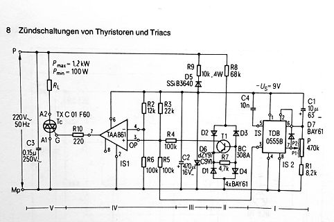
Schaltplan Zündschaltungen von Thyristoren und Triacs
Triacs Pmax = 1,2 kW Pmin = 100 W RL 220V~ 50Hz A2 TX C 01 F60 Tc C3 0.15µ 250V A1 G R10 220 TAA861 OP 6 4 3 7 8 2 IS1 R2 12k R3 22k R4 100k R6 100k R5 100k D5 SSi B3640 C4 10n C2 470 16V D6 ZY97 C9VI D1 D2 T1 D3 IS TDB 0555B BC 308A C1 10µ 63 D7 BAY61 7 1 2 3 4 5 6 8 IS 2 P2 P 470k P1 R1 8,2k 4xBAY61
in „Gibt es ein Triac Treiber IC welches sich um Leistungsverstellung / Paketwellensteuerung kümmert?“ · Analoge Elektronik und Schaltungstechnik · · Schaltpläne
-
PDF
TM56M152A-tenxtechnology.pdf
95.7~0 R/W 00 PWM1DH (96h) Function related to: PWM1 PWM1 Duty bit 15~8 PWM1DH 96.7~0 R/W 80 PWM1DL (97h) Function related to: PWM1 PWM1 Duty bit 7~0 PWM1DL 97.7~0 R/W 00 PWM2DH (98h) Function related to: PWM2 PWM2DH 98.7~0 R/W 80 PWM2 Duty bit 15~8 PWM2DL (99h) Function related to: PWM2 PWM2DL 99.7~0
in „MCU identifikation/Datenblatt - MC9989A0ZQ“ · Mikrocontroller und Digitale Elektronik ·
-
PDF
catalog-3.pdf
]: Amplifiers - Op Amps, Buffer, Instrumentation [Desc]: Op Amp Single Precision Amplifier R-R O/P ±15V 8-Pin SOIC N Tube MPN: OPA121KU/2K5E4 [ID]: 000082 [Price]: undef/offer [QTY]: 5 [Category]: Amplifiers - Op Amps,
-
PDF
NASA_Technical_Note_D-822.pdf
"/2 .i_9179 .1k5709 .1_8525 .15Lx599 .157751 .16_57_ .167_72 .17L_8 7O 80 •2_977 .2578_ ._'_'5D1 ._97_6 .=ppa_ ._1976 .96_96 ._7u_9 ._o855 ._7;98 ,-4 9O .z958_ .500_97 ._o7o98 .5158o2 ._0606 .5_7_88 .p_ .I_1_5 .P_8_92 .55577o i ,-I 100 ._ ._7o_,_ .5"rr_ _2_5,_ ._ ._ ._ .,,1_a8 ._ ._51_59 110 .&_657 .
in „Komplexe Berechnung auf µC - geschickte Annäherung?“ · Mikrocontroller und Digitale Elektronik ·
-
PDF
SPV1040.pdf
= 33 µH 5 PV cells - V = 2.5 V, L = 33 µH mp X mp X PoutPin AM14864v1PiP/max AM14865v1 (%) (%) 98 97 96 Pin = 0.25 W Pin = 0.25 W Pin = 0.5 W Pin = 0.5 W 94 Pin = 1.0 W 95 Pin = 1.0 W Pin = 1.5 W Pin = 1.5 W 92 Pin = 2.0 W Pin = 2.0 W Pin = 2.5 W 93 Pin = 2.5 W 90 Pin = 3.0 W Pin = 3.0 W Pin = 3.5 W
in „Platine Designen für SPV1040“ · Mikrocontroller und Digitale Elektronik ·
-
PDF
uaf42.pdf
Ad2 V 2 13 High-Pass V (1) (1) IN3 O NC 2 15 NC V IN2 3 12 VIN1 V 3 14 High-Pass V IN3 O Auxiliary Op Amp, +In4 11 Ground V 4 13 V IN2 IN1 Auxiliary Op Amp, -In5 10 V+ Auxiliary Op Amp, +In5 12 Ground Auxiliary Op Amp, V 6 9 V- O Auxiliary Op Amp, -In6 11 V+ Bandpass V 7 8 Frequency Adj O 1 Auxiliary
in „Rechteck Sinus“ · Analoge Elektronik und Schaltungstechnik ·
-
Datei
MCP601.txt
******************************************************************************** * * The following op-amps are covered by this model: * MCP601,MCP602,MCP603,MCP604 * * Revision History: * REV A: 30-Jun-99, BCB (created model) * REV B: 10-Jul-99, BCB (corrected DC Iq) * REV C: 30-Nov-99, BCB (".subckt
in „LTSpice: Timestep too small“ · Analoge Elektronik und Schaltungstechnik ·
-
Datei
MCP6001.txt
*************************************************************** * * Macromodel for the MCP6001/2/4 op amp family: * MCP6001,MCP6002,MCP6004 * * Revision History: * REV A: 21-Jun-02, Created model * REV B: 16-Jul-02, Improved output stage * REV C: 03-Jan-03, Added MCP6001 * REV D: 19-Aug-06, Added over
in „Schaltung mit Operationsverstärker in LT-Spice -> Frage zu Bode-Plot“ · Analoge Elektronik und Schaltungstechnik ·
-
Datei
MCP6001.txt
*************************************************************** * * Macromodel for the MCP6001/2/4 op amp family: * MCP6001,MCP6002,MCP6004 * * Revision History: * REV A: 21-Jun-02, Created model * REV B: 16-Jul-02, Improved output stage * REV C: 03-Jan-03, Added MCP6001 * REV D: 19-Aug-06, Added over
in „LTSpice Model für den MCP6001 funktioniert nicht“ · Analoge Elektronik und Schaltungstechnik ·
-
PDF
OM6206U_Z.pdf
System (xS ) LOW 0 0 0 1 0 BS 2 BS 1 BS0 Reserved do not use (reserved for testLOW 0 1 X X X X X X Set OP write OPxto register LOW 1 VOP6 V OP5 V OP4 VOP3 VOP2 VOP1 VOP0 Table 2 Explanations for symbols in Table 1 BIT BIT VALUE DESCRIPTION RESET STATE PD 0 chip is active 1 1 chip is in Power-down mode V
in „Display VG-G090651 von Pollin“ · Mikrocontroller und Digitale Elektronik ·
-
Datei
z80.asm
do_op_rmem16 .dw do_op_rmem8 .dw do_op_da .dw do_op_scf .dw do_op_cpl .dw do_op_ccf .dw do_op_pop16 .dw do_op_push16 .dw do_op_ifnz .dw do_op_ifz .dw do_op_ifnc .dw do_op_ifc .dw do_op_ifpo .dw do_op_ifpe
in „CP/M auf ATmega88“ · Mikrocontroller und Digitale Elektronik ·
-
Datei
avr-m8_z80.asm
do_op_rmem16 .dw do_op_rmem8 .dw do_op_da .dw do_op_scf .dw do_op_cpl .dw do_op_ccf .dw do_op_pop16 .dw do_op_push16 .dw do_op_ifnz .dw do_op_ifz .dw do_op_ifnc .dw do_op_ifc .dw do_op_ifpo .dw do_op_ifpe
in „CP/M auf ATmega88“ · Mikrocontroller und Digitale Elektronik ·
-
PDF
3260.pdf
Settling Time t C = 20 pF — — 20 µs sd L Reverse Battery Current ICC V RCC= -16 V – – -15 mA NOTES:1. . OP= operate point (output turns RP= release point (output turns ON). 2. Typical Data is at T = +25°C a= 12 V and is for design information only. A CC MAGNETIC CHARACTERISTICS over operating supply voltage
in „Schaltnetzteil TNY Ersatztyp Kompatibel ?“ · Analoge Elektronik und Schaltungstechnik ·
-
PDF
behringer_eurolive_b112d_sm.pdf
10k - 100/16 AGND IC4-C 82p R63 4580 C19 100n 100n 1 470p 1 8 VCC 4580 VSS 4 C18 1M 47k IC2-A AGND OP1-B 2 R62 C71 3 + IC5-C EUTEC OPTO 3n3 C26 100n 8 4 C47 100n AGND 3 50KB 1 R55 AGND VCC 4580 VSS C78 5k6 AGND VR1-A AGND R59 R3 IC8-C 7k68 470 100n 100n C40 8 VCC 4580 VSS 4 C77 C66 C61 47p MIC1OUT R77
in „Behringer B112D Funktionsweise Netzteil“ · Analoge Elektronik und Schaltungstechnik ·
-
PDF
C906560.pdf
−28 1839.00 1885.00 2001.49 28 85.90 86.90 87.88 84 8.88 9.20 9.50 −27 29 85 1724.00 1767.00 1872.97 81.97 82.97 83.94 8.57 8.89 9.18 −26 1617.00 1656.00 1753.51 30 78.25 79.23 80.20 86 8.28 8.59 8.87 −25 1517.00 1554.00 1642.43 31 74.71 75.69 76.65 87 8.00 8.30 8.58 −24 32 88 1424.00 1458.00 1538.88
in „Ersatz für ON-Semi STK5Q4U362J-E / STK5Q4U363J-E bzw. passt da NFAQ1060L33T / NFAQ1060L36T“ · Analoge Elektronik und Schaltungstechnik ·
-
PDF
Choosing_the_Correct_Digipot-Analog.pdf
0.90 LGST, 8% R-tol; 2.3 V supply operation AD5231 1024 ±2.75, +5.5 SPI 10, 50, 100 600 TSSOP-16 1.97 28 bytes of user-programmable NVM AD5251 64 ±2.75, +5.5 I C 1, 10, 50, 100 600 TSSOP-14 1.97 % R-tol error stored in NVM, 12 bytes of user-programmable NVM 2 AD5122A New 128 ±2.75, +5.5 I C 10, 100 35
in „Alter Analogverstärker mit Digitalpotis ausstatten“ · Mikrocontroller und Digitale Elektronik ·
-
PDF
LUW_W5AM_Pb_free.pdf
page 21 2) page 21 Brightness Group Luminous Flux Luminous Intensity ΦV (mlm) IV (mcd) KY 82.000 ... 97.000 22.400 (typ.) KZ 97.000 ...112.000 26.100 (typ.) LX 112.000 ...130.000 30.200 (typ.) LY 130.000 ...150.000 35.000 (typ.) Anm.: Die Standardlieferform von Serientypen beinhaltet eine Familiengruppe
-
PDF
LED-Treiber.pdf
= Transistor_ein/Clock_Periode, mittlerer Speicherdrosselstrom Resultat Mittlerer Eingangsstrom = 97mA, Tastverhältn. = 74%, Transistor-Spitzenstrom = 131mA LED-Treiber.doc Seite 10 / 18 H. Hochreutener, SoE@ZHAW 3. LED an Netz-Wechselspannung von 230V / 50Hz Wenn LEDs andere Lampentypen ersetzen sollen
in „cos phi eines Laptop-Netzteils“ · Analoge Elektronik und Schaltungstechnik ·
-
PDF
MAX4249-MAX4257.pdf
EVALUATION KIT AVAILABLE MAX4249–MAX4257 UCSP, Single-Supply, Low-Noise, Low-Distortion, Rail-to-Rail Op Amps General Description Features The MAX4249–MAX4257 low-noise, low-distortion oper- Available in Space-Saving UCSP, SOT23, and ational amplifiers offer rail-to-rail outputs and single- MAX ® Packages
-
PDF
25l2c_OPERATIONAL_AMPLIFIERStlc25m2.pdf
differential voltage V = 1 V to 6 V, R = 1 MΩ 0°C 50 1025 V/mV VD amplification O L 70°C 50 660 25°C 65 97 CMRR Common-mode rejection ratio V = V min 0°C 60 97 dB IC ICR 70°C 60 97 25°C 70 97 k S upp y-vo age re ec on ra o V = 5 V to 10 V,V = 1.4 V 0°C 60 97 dB SVR (∆VDD /∆VDD ) DD O 70°C 60 98 25°C 29 46
in „Merten Dimmaktor (6470 29) keine 0-10V am Ausgang“ · Analoge Elektronik und Schaltungstechnik ·
-
Datei
Descriptions.txt
365 NPN Transistor 217 MICROCONTROLLER 213 CRYSTAL 200 JUMPER 144 Wire PAD connect wire on PCB 114 OP AMP 107 NPN TRANSISTOR 102 THROUGH-HOLE PAD 100 HARTING 97 POTENTIOMETER 94 CONNECTOR 93 SUB-D 92 VOLTAGE REGULATOR 78 OSRAM 72 SAL41B 67 INDUCTOR, European symbol 66 Positive VOLTAGE REGULATOR 65 P-Channel
in „[KiCad] Bibliotheksaufbau - Konzeptideen gesucht“ · Platinen ·
-
 Bild
Bestückte Leiterplatte mit elektronischen Bauteilen
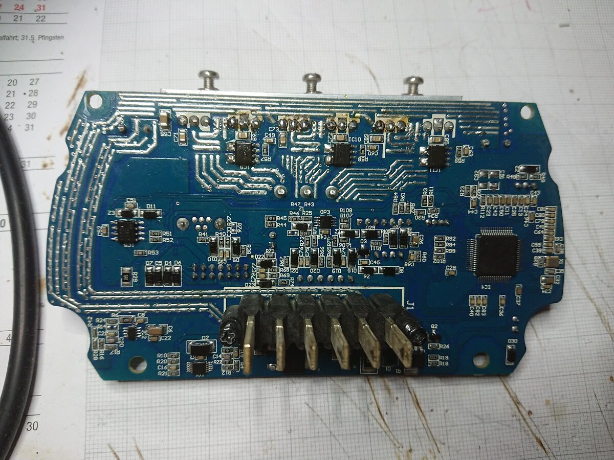
D11 R51 R53 D5 D4 D6 R47 R22 OP3 R107 R108 R45 R44 R46 R48 R49 R50 R52 R54 R55 R56 R57 R58 R59 R60 R61 R62 R63 R64 R65 R66 R67 R68 R69 R70 R71 R72 R73 R74 R75 R76 R77 R78 R79 R80 R81 R82 R83 R84 R85 R86 R87 R88 R89 R90 R91 R92 R93 R94 R95 R96 R97 R98 R99 R100 R101 R102 R103 R104 R105 R106 R107 R108 R109 R110 R111 R112 R113 R114 R115 R116 R117 R118 R119 R120 R121 R122 R123 R124 R125 R126 R127 R128 R129 R130 R131 R132 R133 R134 R135 R136 R137 R138
in „VICTORIA eClassic 3.1 Ladeelektronik“ · Platinen · · Platinenfotos
-
PDF
UKW_Berichte_1963_2019.pdf
cm-Band Schmalbandige Filter für die Bänder bei 23cm, 13cm und 9cm Dieter Vollhardt DL 3 NQ 1977/2 97…106 Filter Schmalbandige Filter für 23 cm, 13 cm, 9 cm Dieter Vollhardt DL 3 NQ 1977/2 97…106 23-cm-Band Schmalbandige Filter für die Bänder 23cm, 13cm und 9cm Dieter Vollhardt DL 3 NQ 1977/2 97…106
-
PDF
Diskreter_Leistungverst_rker_mit_OPVs__-_AN47.pdf
PHOTO= 500nA-350 A Q3 Q4 330 0.1 50 3k PNP = 2N3906 + NPN = 2N3904 –5V A4 OUTPUT LT1016 – LTAN47 • TA97 Figure 97. Adaptively Triggered 40MHz Fiber Optic Receiver is Immune to Shifts in Operating Point gardlessofabsoluteamplitude.Thissignal-adaptivevolt- Figure99usestheLT1193differentialamplifiertoaccom
in „Projekt: DDS basierter Funktionsgenerator mit AD5930“ · Mikrocontroller und Digitale Elektronik ·
-
PDF
TDA7293.pdf
CLIP DET VSTBY STBY 9 STBY R4 22K 1 8 15 STBY-GND -Vs -PWVs C3 10 F C4 10 F C9 100nF C8 1000 F -Vs D97AU805A (*) see Application note (**) for SLAVE function December1999 1/13 TDA7293 PIN CONNECTION (Topview) 15 -VS(POWER) 14 OUT 13 +VS(POWER) 12 BOOTSTRAP LOADER 11 BUFFER DRIVER 10 MUTE 9 STAND-BY 8
in „Kann mir jemand helfen. Wer ist der Hersteller der Audio Boards "YUANJING"“ · Analoge Elektronik und Schaltungstechnik ·
-
Datei
1.txt
based SSDs Device Model: OCZ-VECTOR150 Serial Number: OCZ-D88RRV800KYK5WEO LU WWN Device Id: 5 e83a97 4446a4617 Firmware Version: 1.2 User Capacity: 120,034,123,776 bytes [120 GB] Sector Size: 512 bytes logical/physical Rotation Rate: Solid State Device Device is: In smartctl database [for details use
in „[V] SATA SSD/HDDs“ · Markt ·
-
Datei
avr-m8_z80.asm
do_op_rmem16 .dw do_op_rmem8 .dw do_op_da .dw do_op_scf .dw do_op_cpl .dw do_op_ccf .dw do_op_pop16 .dw do_op_push16 .dw do_op_ifnz .dw do_op_ifz .dw do_op_ifnc .dw do_op_ifc .dw do_op_ifpo .dw do_op_ifpe
in „CP/M auf ATmega88“ · Mikrocontroller und Digitale Elektronik ·
-
Datei
avr-m8_z80.asm
do_op_rmem16 .dw do_op_rmem8 .dw do_op_da .dw do_op_scf .dw do_op_cpl .dw do_op_ccf .dw do_op_pop16 .dw do_op_push16 .dw do_op_ifnz .dw do_op_ifz .dw do_op_ifnc .dw do_op_ifc .dw do_op_ifpo .dw do_op_ifpe
in „CP/M auf ATmega88“ · Mikrocontroller und Digitale Elektronik ·
-
Datei
avr_cpm.asm
do_op_rmem16 .dw do_op_rmem8 .dw do_op_da .dw do_op_scf .dw do_op_cpl .dw do_op_ccf .dw do_op_pop16 .dw do_op_push16 .dw do_op_ifnz .dw do_op_ifz .dw do_op_ifnc .dw do_op_ifc .dw do_op_ifpo .dw do_op_ifpe
in „CP/M auf ATmega88“ · Mikrocontroller und Digitale Elektronik ·
-
PDF
OPV_LT1359CN.pdf
LT1358/LT1359 Dual and Quad 25MHz, 600V/µs Op Amps U FEATURES DESCRIPTIO ■ 25MHz Gain Bandwidth The LT1358/LT1359 are dual and quad low power high ■ 600V/µs Slew Rate speedoperationalamplifierswithoutstandingACandDC ■ 2.5mA MaximumSupply Current
in „Operationsverstärker (OPV) wird heiß als Summierer“ · Analoge Elektronik und Schaltungstechnik ·
-
PDF
LT1358__25MHz__LT.pdf
LT1358/LT1359 Dual and Quad 25MHz, 600V/µs Op Amps U FEATURES DESCRIPTIO ■ 25MHz Gain Bandwidth The LT1358/LT1359 are dual and quad low power high ■ 600V/µs Slew Rate speedoperationalamplifierswithoutstandingACandDC ■ 2.5mA MaximumSupply Current
in „defekte LT1358“ · Analoge Elektronik und Schaltungstechnik ·
-
PDF
vestel_17mb95m_r2-1_sch.pdf
7 6 5 4 3 2 1 N LG BASED 30070519 10k 1 5 k C 4 k 2 3 5 3 2 R235 9 0 R N N N PANEL_VCC 33k OP_PIN7 R 1 2 P P P R81 2 _ _ _ 1 2 3 O O O 10k 1 S57 2 2 R95 1 2 Q23 PANEL_VCC 1 S39 2 PANEL_VCC_ON/OFF 10k BC848B MEGA_DCR_IN B R221 1 B 2 PANEL_VCC 33k OP_PIN8 C141 1 0 9 8 7 6 5 4 3 2 1 0 9 8 7 6 5
in „Vestel TV Board 17MB95M zwei SMD Bauteile finden“ · Analoge Elektronik und Schaltungstechnik ·
-
PDF
gesamtinhalt-1967-2019_Call_Heft.pdf
187 Amateur- Fernsehen Vereinfachte Induktivitätsbestimmung kleiner Luftspulen Hubertus Rathke DC 1 OP 1979/3 158…159 Grundlagen neue Techniken ATV-FM-Steuersender für das 13-cm-Band Hubertus Rathke DC 1 OP 1987/4 204 – 214 Oszillatoren ATV-FM-Steuersender für das 13-cm-Band Hubertus Rathke DC 1 OP 1987/4 204…214 Amateurfernsehen Ein Uni(versal)-Zähler bis 12 GHz Hubertus Rathke DC 1 OP 2004/2 85…93 Messtechnik Ein interessantes Bauteil: ADF 4360 von Analog Devices Hubertus Rathke DC 1 OP 2010/2 67…73 Bauteile-Info ATV-FM-Steuersender für das 13-cm-Band Hubertus Rathke DC 1 OP 1987/
-
PDF
gesamtinhalt-1967-2019_HeftNr.pdf
cm-Band Schmalbandige Filter für die Bänder bei 23cm, 13cm und 9cm Dieter Vollhardt DL 3 NQ 1977/2 97…106 Filter Schmalbandige Filter für 23 cm, 13 cm, 9 cm Dieter Vollhardt DL 3 NQ 1977/2 97…106 23-cm-Band Schmalbandige Filter für die Bänder 23cm, 13cm und 9cm Dieter Vollhardt DL 3 NQ 1977/2 97…106
-
PDF
D_CH23103.pdf
sehen. Dank der optimalen Kopplung zwischen dem Primärkreis und der Kompensa- Zur Gewissheit, dass OP1 nicht gesättigt ist: OP1 Ausgangs- tionswicklung kann der Transformator-Effekt optimiert spannung = 2,7 V - Rspule I = 1,116 V. S werden. 1,116 V > 0,5 V = OP1 Sättigungspegel; wir sehen, dass es kein
in „Transducer LEM HAIS-50“ · Mikrocontroller und Digitale Elektronik ·
-
PDF
D_CH23103.pdf
sehen. Dank der optimalen Kopplung zwischen dem Primärkreis und der Kompensa- Zur Gewissheit, dass OP1 nicht gesättigt ist: OP1 Ausgangs- tionswicklung kann der Transformator-Effekt optimiert spannung = 2,7 V - Rspule I = 1,116 V. S werden. 1,116 V > 0,5 V = OP1 Sättigungspegel; wir sehen, dass es kein
in „LTS25-NP Stromwandler am ATmega -> Spannungsverstärkung muss wohl her“ · Mikrocontroller und Digitale Elektronik ·
-
PDF
D_CH23103.pdf
sehen. Dank der optimalen Kopplung zwischen dem Primärkreis und der Kompensa- Zur Gewissheit, dass OP1 nicht gesättigt ist: OP1 Ausgangs- tionswicklung kann der Transformator-Effekt optimiert spannung = 2,7 V - Rspule I = 1,116 V. S werden. 1,116 V > 0,5 V = OP1 Sättigungspegel; wir sehen, dass es kein
in „Messung mit Stromwandler LTSR 15-NP“ · Analoge Elektronik und Schaltungstechnik ·
-
PDF
D_CH23103.pdf
sehen. Dank der optimalen Kopplung zwischen dem Primärkreis und der Kompensa- Zur Gewissheit, dass OP1 nicht gesättigt ist: OP1 Ausgangs- tionswicklung kann der Transformator-Effekt optimiert spannung = 2,7 V - Rspule I = 1,116 V. S werden. 1,116 V > 0,5 V = OP1 Sättigungspegel; wir sehen, dass es kein
in „Wo Entstörkondensatoren in meiner Schaltung?“ · Mikrocontroller und Digitale Elektronik ·
-
PDF
D_CH23103.pdf
sehen. Dank der optimalen Kopplung zwischen dem Primärkreis und der Kompensa- Zur Gewissheit, dass OP1 nicht gesättigt ist: OP1 Ausgangs- tionswicklung kann der Transformator-Effekt optimiert spannung = 2,7 V - Rspule I = 1,116 V. S werden. 1,116 V > 0,5 V = OP1 Sättigungspegel; wir sehen, dass es kein
in „Strommessung mit Hallsensor“ · Mikrocontroller und Digitale Elektronik ·
-
PDF
LTSR.pdf
sehen. Dank der optimalen Kopplung zwischen dem Primärkreis und der Kompensa- Zur Gewissheit, dass OP1 nicht gesättigt ist: OP1 Ausgangs- tionswicklung kann der Transformator-Effekt optimiert spannung = 2,7 V - Rspule I = 1,116 V. S werden. 1,116 V > 0,5 V = OP1 Sättigungspegel; wir sehen, dass es kein
in „LEM-Wandler Datenblatt“ · Analoge Elektronik und Schaltungstechnik ·
-
PDF
D_CH23103.pdf
sehen. Dank der optimalen Kopplung zwischen dem Primärkreis und der Kompensa- Zur Gewissheit, dass OP1 nicht gesättigt ist: OP1 Ausgangs- tionswicklung kann der Transformator-Effekt optimiert spannung = 2,7 V - Rspule I = 1,116 V. S werden. 1,116 V > 0,5 V = OP1 Sättigungspegel; wir sehen, dass es kein
in „Stromsensor von LEM prüfen“ · Analoge Elektronik und Schaltungstechnik ·