
-
PDF
R2E140AL4005-DB-GER.pdf
60 80 100 120 140 160 180 200 220 240 260 280 300 320 340 360 380 400 420 440 qv[m^3/h] Messwerte U f n P e I LpA in LwA in qV pfs q V pfs -1 3 V Hz min W A dB(A) dB(A) m /h Pa cfm in. wg 1 230 50 1650 135 0,60 62 69 415 0 245 0,00 2 230 50 2095 111 0,48 62 68 355 200 210 0,80 3 230 50 2350 98 0,43
-
PDF
SA430.PDF
4 5 6 7 8 9 0 1 2 3 4 5 6 7 U3U LPii2 . . . . . . . V / / / / / / / / PIU307GND D PIU304 PILPi20PILPi202 P P P P P P P D 3 3 3 3 3 3 3 3 PR91R91 PR910910 PI3305GND C PI6302 18nH P P P P P P P P 1k5 1k5 PIU301GND B PIU308 PICOCi2
in „TI CC430 MCU als Spectrum Analyzer“ · HF, Funk und Felder ·
-
 Bild
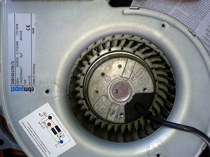
ebm-papst Lüfter mit Typenschild und Anschlussplan
ebm papst D2E135-C133-73 230V~ 50/60Hz 0,77/0,84A 1700/2100min-1 TOP 4µF 175/190W 400VDB CE 18/08 Made in Germany Ins.Cl.B L1 N PE U L2
in „Wie Lüfter weiter zerlegen?“ · Mechanik, Gehäuse, Werkzeug · · Fotos
-
PDF
DE_20DE0001_TECHNIK_LEITUNGSSCHUTZSCHALTER.PDF
Spannungsunterbrechnung M Z203 M Z204 M Z205 M Z206 4560 030 4560040 -- Anwendung: 4 560057 -- Anwendung: B E BE B MT BM T 230 4-0VC1 1 4-2 C1 Fernausschaltung des LS-Schalters 48 V D1 230 V D1 Sicherheitsaspekt z. B. im Falle eines (z. B. Sicherheitsaspekt) U< U < Spannungsausfalls an Motoren (Kreissäge C2
in „Heizstrahler Schalterkontakt brennt fest“ · Analoge Elektronik und Schaltungstechnik ·
-
PDF
uhp-ma_e.pdf
JYd120/A.C 圆 85 VPL-SC60/M JYd120/A.C 65×70 TLP-511E/Z JYd120/A.C 圆 85 VPL-SCM/M JYs200/D.C 65×70 B TLP-510Z JYd120/A.C 圆 85 VPL-PX30 JYs120/D.C TLP-471/E/Z JYs150/D.C 65×70 VPL-PX31 JYs120/D.C A TLP-470/E/Z JYs150/D.C 65×70 VPL-PX21 JYs20O/D.C TLP-470A JYd150/A.C VPL-PX20 JYs200/D.C TLP-450E/E/U JYd150
in „Beamer 'wiederverwerten'?“ · Mikrocontroller und Digitale Elektronik ·
-
PDF
Nichicon.pdf
numbering system (Example : 200V 680µF) Polarity bar Sleeve P.E.T. 1 2 3 4 5 6 7 8 9 10 11 12 . L G U 2 D 6 8 1 M E L A A + Case dia. code φ Configuration φD Code 10 Capacitancetolerance(±20%) 20 Y L±2 22 Z Rated capacitance (680µF) Pressure relief vent 4.0±0.5 Rated voltage (200V) 25 A 30 B Series name
in „Welche Elkos taugen was?“ · Analoge Elektronik und Schaltungstechnik ·
-
PDF
Reparaturanleitung.pdf
durch den R42-Filter gespeist. für solche Geräte. U1, C10-U1, R25-U1, C3-U1 aus der Quelle ähnliches Klassenstrukturdiagramm –12 V und durch den Filter R30-U1, C7-U1, (Abb. 2). Es enthält einen vertikalen Ablenkkanal A B R27-U1, C4-U1 von einer +12-V-Quelle
in „Altes Oszi aus USSR (C1-94). Strahlrücklauf sichtbar.“ · Analoge Elektronik und Schaltungstechnik ·
-
Datei
SDRSharp_20190803_155652Z_145802000Hz_IQ_ISS_okay_bild.txt
...p...h36b..... 18:09:10$ fm DK3RW-9 to U0SXV2-0 via DB0REI-10,DB0GIS-10,DB0FDA-0 UI PID=F0 `~WCo,`>/"7<}Ralf.F07 18:09:15$ fm DK3RW-9 to U0SXV6-0 via DB0GIS-10,WIDE1-0,DB0FDA-0 UI PID=F0 `~W@nf8>/"7:} 18:09:15
in „SDR: ISS SSTV Signal durch Digipeater gestört - Quelle finden“ · HF, Funk und Felder ·
-
PDF
MEGA_1284P_Xplained_Schematic.pdf
POPOWER0LED GND I201 PRTR5V0U2X TP200 I21 Power LED and USB Status LED TP201 USB Transient protection B B LEDS&BUTTONS VCC_P3V3 VCC_P3V3 VCC_P3V3 VCC_P3V3 2 2 2 2 A 0 A P5 A D4 A 03 2 C 5C 4 C 3 C 01C200 C20 U O02U D2 U C20 U D 2
in „MEGA1284P XPLAINED über USB mit avrdudue programmieren“ · Mikrocontroller und Digitale Elektronik ·
-
PDF
DE_16DE0001_TECHNIK_LEITUNGSSCHUTZSCHALTER.pdf
Normen DIN EN 60898-1, IEC 60898-1, VDE 0641-11 Polzahl 1, 2, 3, 4, 1 + N, 3 + N Auslösecharakteristik B C B C D Bemessungsspannung U n einpolig 230 / 400 V~ mehrpolig 400 V~ max. Bemessungsbetriebsspannung AC einpolig 230 / 400 V~ mehrpolig 400 V~ DC einpolig 60 V zweipolig (bei Reihenschaltung beider
in „Fi-Schutzschalter nur für die Hälfte der Wohnung?“ · Haus & Smart Home ·
-
PDF
id_ni-mh_1104_e.pdf
1 It80 t <1 year -20 to +35 a 3 0 10 20 30 40 50 60 70 80 e o 0.8 1400mA(2 It) e o 1 2 750mA(1 It) b Storage (°C) <6 months -20 to +45 V 1.1 Discharge time (minutes) b Storage (°C) <6 months -20 to +45 V 0.8 Discharge time (minutes) 1500mA(2 It) m 0 10 20 30 40 50 60 70 80 m 1 10 10 20 30 40 50 60 70
in „Mit welcher Spannung lädt man eine NIMH Zelle?“ · Analoge Elektronik und Schaltungstechnik ·
-
PDF
Netzteil_NT255_30V-6A.pdf
- Glimmerscheiben und Isolierbuchsen. ,’ i’ir empfehlen unbedingt die Verwendung eines Der AnschluB erfolgt lt. Abbildung: Jetztrafo m i t M i t t e l a b g r i f f . ! ! ! 1 H i e r d u r c h lird die Thermische Belastung vcn T 2 - T 3 erheblich reduziert.“Beispiel: “Normal-Trafo” 28V Transistor 2.-N3771 . .angenommen es werden 12 V = bei 3 A ßelastung (oder Vergleich) lenötigt.Die “Schaltung” u. insbesondere die .eistungstransistoren müssen rund 16V/ 3A B=. Basis n nutzlose, ja Thermische Wärme “verwandeln” . C= Kollektor(am Gehäuse) EierGber sind T 2 ! T3 nicht besonders “erfreut”! InbetriePnahme
in „Conrad-Netzteilbausatz 30V / 7A 'Diamant' - Schaltplan gesucht?“ · Analoge Elektronik und Schaltungstechnik ·
-
PDF
CAN_uC_V2_CPU_27Aug2011.pdf
0 1 (AN255-02 Philips (NXP)) 1 C 1 C 1 C 1 C unter dem R 1 C15 22p Extern Prozessor R4 1 2 D 116 2 B 2 B 2 B 2 B 44 43 42 41 40 39 38 37 36 35 34 1 3 2 N TWI_SCL 1 2 N N N N 6 5 4 3 2 1 0 3 2 1 C Q2 G 2 TWI_SDA R17 100R GND RC7 C C C D D D D C C C N NC 10MHZ 100n R5 1 2100R 1 R R R R R R R R R R 33
in „Anforderungssammlung CAN Hausbus mit PIC µC“ · Haus & Smart Home ·
-
PDF
FKN.pdf
F K NW ireW o u n dF u sib leR e sisto r Features ⅠFunction as a resistor in normal operation condition. ⅡQuick fusing protects circuit from excessive over load. ⅢApprovals awarded; UL 1412 File No.E341249. ⅣProducts meet EU-RoHS. Construction a b c d e f a Leadwire b Cap c Ceramicbase d Wirewound e Markingorcolorcode Dimensions f Insulationcoat t t Φd H L H p ow er D im ensions(m m ) W eight(g) T ype (W ) (1000pcs) L± 1.0 t M ax D± 0.5 Φ d± 0.05
in „Widerstand welche Größe“ · Analoge Elektronik und Schaltungstechnik ·
-
PDF
schematics.pdf
TEMP_IN TEMP_OUT TEMP_MOTOR PIP101 5V GND B6B-PH-K-S P3 PIP301 2 5V SERVO PIP302 VCC PIP403 GND PIP304 SCK_ADC_EXT PIP305 TX_SDA_NSS C PIP306 RX_SCL_MOSI LED_GREEN C PIP307 MISO_ADC_EXT2 LED_RED VCC B7B-PH-K-S PRCR3 PCO3 PCO2 U_temp 100R 100R
in „BLDC Motorcontroller 200A 48V basierend auf VESC“ · Analoge Elektronik und Schaltungstechnik ·
-
Datei
mv_gcctest9.lst
6D61 6C2E 91 00 92 .data 93 .LC0: 94 0000 5072 6573 .string "Press any key..." 94 7320 616E 94 7920 6B65 94 792E 2E2E 94 00 95 .LC1: 96 0011 6131 363F .string "a16? %u\r\n" 96 2025 750D 96 0A00 97 .LC2: 98 001b 5469 636B .string "Ticks1? %u\r\n" 98 7331 3F20 98 2575 0D0A 98 00 99 .LC3: 100 0028 5469 636B .string "Ticks2? %u\r\n" 100 7332 3F20 100 2575 0D0A 100 00 101 .LC4: 102 0035 6454 6963 .string "dTicks? %u us\r\n" 102 6B73 3F20 102 2575 2075 102 730D 0A00 103 .text 105 .global main 107 main: 1:mv_gcctest9.c **** /*
in „Multiplikation ist zu schnell...“ · Mikrocontroller und Digitale Elektronik ·
-
PDF
5521f.pdf
Leakage vs LO Frequency Figure vs Supply Voltage vs LO Power –36 10 30 10 25 IIP3 P –38 8 25 3 8 24 B IIP3 –40°C m 6 23 )–40 6 85°C 20 A B 25°C D P ( 85°C B –40°C N B4 22 3 G–42 ( 4 NF 15 I ( 85°C B K GC E G 25°C m E I 2 –40°C 21 ) L–44 25°C 2 10 U GC E 0 20 GC d –46 0 5 B ) –2 19 –48 –2 0 –4 18 1500
in „Anpassung Differenztialeingang LT5521“ · HF, Funk und Felder ·
-
PDF
PM55L-048-E.pdf
Voltage 24[V] 24[V] Current / Phase 600[mA] Coil Resistance / Phase 30[ ] 6[ ] Drive I C SMDT-002 UDN2916B-V Magnet Material Ferrite plastic magnet Polar anisotropy ferrite sintered magnet Nd-Fe-B bonded magnet Insulation Resistance 100M[ ] MIN Dielectric Strength AC 500[V] 1[min] Class of Insulation CLASS
in „Welcher Schrittmotor für Drehpodest?“ · Mikrocontroller und Digitale Elektronik ·
-
PDF
Ender3_schematic.PDF
4 5 6 7 8 Power VMOT VCC VCC CU UP1 MP1584 LP1 FP1 PIP10 VIN SW PIU101 PIP0 PI11 PF11PIP0 功率电感 -15uH/3A 1.5A P6 VMOT PI PI2 PI2 P0 CP2 R262 PWR PI COC R_P1 COP1 DP1 "Power inductor" U8U P6k PIWR0 30 PI100k PI 0.1uF B340A-13-F 22uF ENDTEMP PIU830 PU804 RESET 1 100uF 2 8 PI P0 BEDTEMP 31 ADC7/PCINT7/
in „Problem mit SD Card Melzi Creality3D V1.1.3 Sanguino Atmega 1284“ · Mikrocontroller und Digitale Elektronik ·
-
PDF
irfp2907.pdf
Maximum Avalanche Energy Fig 12b. Unclamped Inductive Waveforms Vs. Drain Current Q G 10 V Q GS QGD 4.0 VG 3.5 ) V ( 3.0 c Charge i ID = 250µA a Fig 13a. Basic Gate Charge Waveform V 2.5 Current Regulator ) Same Type as D.U.T. t S 2.0 G 50KΩ V 12V .2µF .3µF 1.5 + D.U.T. -DS 1.0 -75 -50 -25 0 25 50 75 100 125 150 175 VGS 3mA T , Temperature ( °C ) J G D Current Sampling Resistors Fig 14. Threshold Voltage Vs. Temperature Fig 13b. Gate Charge Test Circuit 6 www.irf.com
in „Sinusendstufe für 300A“ · Mikrocontroller und Digitale Elektronik ·
-
PDF
IRFP2907.pdf
Maximum Avalanche Energy Fig 12b. Unclamped Inductive Waveforms Vs. Drain Current Q G 10 V Q GS QGD 4.0 VG 3.5 ) V ( 3.0 c Charge i ID = 250µA a Fig 13a. Basic Gate Charge Waveform V 2.5 Current Regulator ) Same Type as D.U.T. t S 2.0 G 50KΩ V 12V .2µF .3µF 1.5 + D.U.T. -DS 1.0 -75 -50 -25 0 25 50 75 100 125 150 175 VGS 3mA T , Temperature ( °C ) J G D Current Sampling Resistors Fig 14. Threshold Voltage Vs. Temperature Fig 13b. Gate Charge Test Circuit 6 www.irf.com
in „Auto-Kühler-Lüfter per PWM manuell steuern“ · Analoge Elektronik und Schaltungstechnik ·
-
PDF
Layout_f_rs_Display.pdf
dieser Baugrößen gelesen. Leider war ich schwer oft fehlende Funk- und beträgt bei Mignon typisch 2100 mAh und bei Micro enttäuscht, dass die Software tion einer Buch- 800 mAh. Ansonsten unterscheiden sich die neuen Akkus nur im .Hex-Format zum sensperre/eines akusti- nicht von bisherigen NiMH-Akkus,
in „Siemens M55 Display Datenblatt Ansteuerung“ · Mikrocontroller und Digitale Elektronik ·
-
PDF
Schematic.pdf
1 2 3 4 5 6 Spannungsversorgung Relaisschaltung V V V 1P 2 5 5 U2 AMS1117-3.3 3 HV.P F1 S14K275 600 + + 3 D 2*2 + 3 HV.P IN NOUT 4 A 0,4A L1 G I1.► K1 A + C5 +C3 C6 1 +C4 5 O1.▲ 7 ~ C11 C8 C9 R - 4,7µ 47µ 4,7µ 1 ROLL2 1 2 - 22µ 100n 22µ 47µ 2 Z Z 2 HV.N E E R R . 1 K K 1 V GND GND H 3 O2.▼ WIFI-Modul I2 4 K2 3 5 3 + MDL1 3 3 ESP8266_ESP12E 3 3 B REST REST TXD TXD + + B ADC ADC RXD RXD CH_PD CH_PD GPIO5 GPIO5 IO_O2 8 k 9 k GPIO16 GPIO16 GPIO4 GPIO4 IO_O1 R 1 R 1 UART 5 4 5 4 I²C_SCLGPIO14 GPIO14 GPIO0 GPIO0 + 4 + 4 IO_I1 GPIO12 GPIO12 GPIO2 GPIO2
in „ESP8266 - UP-Modul zur Rolladensteuerung bzw. als Kreuzschalter für Lichtinstallationen“ · Projekte & Code ·
-
PDF
_APT30M40JVFR_A-601394.pdf
R P N A VDS>DI(ON) DS(ON)MAX. O ( 90 250 SEC. PULSE TEST C 1.1 N @ <0.5 % DUTY CYCLE R VGS =10V E U R S U 60 - 1.0 C - VGS =20V I I A T = +125°C A D 30 J R 0.9 , T = +25°C T = -55°C , I J J N ( 0 S 0.8 0 2 4 6 8 RD 0 40 80 120 160 200 V , GATE-TO-SOURCE VOLTAGE (VOLTS) I , DRAIN CURRENT (AMPERES) GS
in „SOT-227 Leistung Gehäuse im Linearbetrieb?“ · Analoge Elektronik und Schaltungstechnik ·
-
PDF
mkp_b32714h_718h.pdf
5.0 14.0 15.0 0.8 4.4 2100 3.0 13.5x23.0x31.5 – B32714H9305+000 6.2 5.4 12.6 16.0 0.8 4.7 1932 4.0 15.0x24.5x31.5 – B32714H9405+000 7.6 6.6 9.5 17.0 0.8 4.8 1680 5.0 16.0x30.0x31.5 – B32714H9505+000 8.6 7.5 7.8 20.0 0.8 4.9 1064
in „[V] MKP-Kondensatoren 4 µF und 100 nF mit 1 kV Spannungsfestigkeit“ · Markt ·
-
PDF
LGT8FX8P_databook_v1.0.4.pdf
LDD/STD 指令高效的在 uDSC 与 SRAM 以及通用寄存器文件之间进行 16 位数 据交换。 为了不破坏正常的LD/ST指令系统, LGT8XM内核把SRAM空间重映射到0x2100~0x28FF。 使用 LD/ST 指令从 0x2100~0x28FF 空间访问 SRAM 时, 内核自动开启 16 位 LD/ST 功能,打 开 SRAM 与 uDSC 之间的直接存取通道。 下图为 LGT8XM 内核的数据空间地址分布: 0x0000 Register File 8b uDSC 0x0020 8/16b I/O 8/16b 8b 0x0060 Ext I/O 8b 0x0100 G 2Kx8 8b 8 SRAM M 2Kx8 L SRAM 0x0900 S I t 0x2100 f C I e R R 1Kx16 16b 16b X Y L H D SRAM uDSC 0x2900 如上图所示,LGT8XM 内核可以通过使用 LD/ST 指令,在 uDSC 的
in „Spot Welder Firmware Update fehlerhaft“ · Mikrocontroller und Digitale Elektronik ·
-
PDF
LGT8FX8P_databook_v1.0.4.pdf
LDD/STD 指令高效的在 uDSC 与 SRAM 以及通用寄存器文件之间进行 16 位数 据交换。 为了不破坏正常的LD/ST指令系统, LGT8XM内核把SRAM空间重映射到0x2100~0x28FF。 使用 LD/ST 指令从 0x2100~0x28FF 空间访问 SRAM 时, 内核自动开启 16 位 LD/ST 功能,打 开 SRAM 与 uDSC 之间的直接存取通道。 下图为 LGT8XM 内核的数据空间地址分布: 0x0000 Register File 8b uDSC 0x0020 8/16b I/O 8/16b 8b 0x0060 Ext I/O 8b 0x0100 G 2Kx8 8b 8 SRAM M 2Kx8 L SRAM 0x0900 S I t 0x2100 f C I e R R 1Kx16 16b 16b X Y L H D SRAM uDSC 0x2900 如上图所示,LGT8XM 内核可以通过使用 LD/ST 指令,在 uDSC 的
-
Datei
asm.txt
(uint32_t value) { uint32_t result; #if (__CORTEX_M >= 0x03U) || (__CORTEX_SC >= 300U) __ASM volatile ("rbit %0, %1" : "=r" (result) : "r" (value) ); 8001b2c: 6a7a ldr r2, [r7, #36] ; 0x24 8001b2e: fa92 f2a2 rbit r2, r2 8001b32: 623a str r2, [r7, #32] result |
in „NUCLEO-L432KC Blinky Projekt mit 11kB Speicherverbrauch“ · Mikrocontroller und Digitale Elektronik ·
-
PDF
irf3708.pdf
On-Resistance Vs. Drain Current Fig 13. On-Resistance Vs. Gate Voltage Current Regulator Same Type as D.U.T. QG 50KΩ VGS 12V .2µF .3µF + GS QGD D.U.T-DS 600 VG ) ID VGS J TOP 10A 3mA ( Charge y 20.7A IG D r 480 BOTTOM 24.8A Current Sampling Resistors n E e Fig 14a&b. Gate Charge Test Circuit c 360 and Waveform n a v A s 240 u P 15V l n 120 V(BR)DSS i tp VDS L DRIVER , S A RG D.U.T + E 0 AS -VDDA 25 50 75 100 125 150 175 20V Starting T , Junction Temperature ( C)° I tp 0.0Ω J AS Fig 15a&b. Unclamped Inductive Test circuit
in „IRF3708 als Schalter“ · Mikrocontroller und Digitale Elektronik ·
-
Datei
dtmf-decoding-encoding.txt
] / 128.0; #endif for(j=0; j<NUMTONES; j++) { t = u0[j]; u0[j] = in + coef[j] * u0[j] - u1[j]; u1[j] = t; } } for(j=0; j<NUMTONES; j++) /* feedforward */ power[j] = u0[j] * u0[j] + u1[j] * u1[j] - coef[j] * u0[j] * u1[j]; return(0); } /* * detect which
in „CTCSS decoder / encoder“ · Mikrocontroller und Digitale Elektronik ·
-
PDF
Testboard_KK32F7.PDF
SD_CD SD_CD CS_FLASH CS_FLASH HAL_A HAL_A HAL_B HAL_B B B U_KK32F7_Sheet4 MOT_CURRENT MOT_CURRENT KK32F7_Sheet4.SchDoc ADC_HOME ADC_HOME INF_MOT_VCC INF_MOT_VCC UTR_A UTR_A LCD_R[0..7] LCD_R[0..7] UTR_B UTR_B LCD_G[0..7] LCD_G[0..7] PWM_A PWM_A LCD_B
in „STM32F7 Discovery Board“ · Mikrocontroller und Digitale Elektronik ·
-
PDF
IRF3708PBF.pdf
On-Resistance Vs. Drain Current Fig 13. On-Resistance Vs. Gate Voltage Current Regulator Same Type as D.U.T. QG 50KΩ V GS 12V .2µF .3µF + QGS QGD D.U.T-VDS 600 G J ID VGS m TOP 10A 3mA ( 20.7A Charge g IG D e480 BOTTOM 24.8A Current Sampling Resistors n E h Fig 14a&b. Gate Charge Test Circuit c360 and Waveform a a v A l240 u P 15V l n120 V(BR)DSS S tp DS L DRIVER , S A R G D.U.T + E 0 AS -VDDA 25 50 75 100 125 150 175 20V Starting T , Junction Temperature ( C) I p 0.01 J AS Fig 15a&b. Unclamped Inductive Test circuit Fig
in „Transistor zum Schalten von 24V/12V“ · Analoge Elektronik und Schaltungstechnik ·
-
PDF
IRF3708_IR__1_.pdf
On-Resistance Vs. Drain Current Fig 13. On-Resistance Vs. Gate Voltage Current Regulator Same Type as D.U.T. QG 50KΩ V GS 12V .2µF .3µF + QGS QGD D.U.T-VDS 600 G J ID VGS m TOP 10A 3mA ( 20.7A Charge g IG D e480 BOTTOM 24.8A Current Sampling Resistors n E h Fig 14a&b. Gate Charge Test Circuit c360 and Waveform a a v A l240 u P 15V l n120 V(BR)DSS S tp DS L DRIVER , S A R G D.U.T + E 0 AS -VDDA 25 50 75 100 125 150 175 20V Starting T , Junction Temperature ( C) I p 0.01 J AS Fig 15a&b. Unclamped Inductive Test circuit Fig
in „Mosfet Treiberschaltung“ · Mikrocontroller und Digitale Elektronik ·
-
PDF
IRF3708_IR__1_.pdf
On-Resistance Vs. Drain Current Fig 13. On-Resistance Vs. Gate Voltage Current Regulator Same Type as D.U.T. QG 50KΩ V GS 12V .2µF .3µF + QGS QGD D.U.T-VDS 600 G J ID VGS m TOP 10A 3mA ( 20.7A Charge g IG D e480 BOTTOM 24.8A Current Sampling Resistors n E h Fig 14a&b. Gate Charge Test Circuit c360 and Waveform a a v A l240 u P 15V l n120 V(BR)DSS S tp DS L DRIVER , S A R G D.U.T + E 0 AS -VDDA 25 50 75 100 125 150 175 20V Starting T , Junction Temperature ( C) I p 0.01 J AS Fig 15a&b. Unclamped Inductive Test circuit Fig
in „24V-Ausgang potentialgetrennt aus einem STM32 3,3V“ · Mikrocontroller und Digitale Elektronik ·
-
PDF
datasheet.pdf
notice, the specifications and information contained herein. - 5 0 TYPICAL PERFORMANCE CURVES APT100GN60B2(G) 300 350 VGE = 15V 15V 13V ) 250 ) 300 ( ( T T 12V N TJ= 175°C N 250 R 200 R R R U TJ= 125°C U 200 11V C C O 150 O T TJ= 25°C T 150 E E 10V L 100 L O O 100 C TJ= -55°C C 9V ,C ,C I 50 I 50 8V 7V 0
in „Dicken Kondensator aufladen & Kurzschließen“ · Analoge Elektronik und Schaltungstechnik ·
-
PDF
663X-Specification_5990-9303EN.pdf
without a complicated test setup. done using industry standard SCPI Specifications Specifications 6631B 6632B 6633B 6634B (at 0 ° to 55 °C unless other wise specified) Number of outputs 1 1 1 1 GPIB Yes Yes Yes Yes Output ratings Voltage 0 to 8 V 0 to 20 V 0 to 50 V 0 to 100 V Current 0 to 10 A 0 to 5
in „Muss die Ladespannung exakt 4,2V betragen?“ · Analoge Elektronik und Schaltungstechnik ·
-
PDF
663X-Specification_5990-9303EN.pdf
without a complicated test setup. done using industry standard SCPI Specifications Specifications 6631B 6632B 6633B 6634B (at 0 ° to 55 °C unless other wise specified) Number of outputs 1 1 1 1 GPIB Yes Yes Yes Yes Output ratings Voltage 0 to 8 V 0 to 20 V 0 to 50 V 0 to 100 V Current 0 to 10 A 0 to 5
in „DC/DC-Wandler von 2.4 V auf 15 V mit 25 Watt“ · Analoge Elektronik und Schaltungstechnik ·
-
PDF
663X-Specification_5990-9303EN.pdf
without a complicated test setup. done using industry standard SCPI Specifications Specifications 6631B 6632B 6633B 6634B (at 0 ° to 55 °C unless other wise specified) Number of outputs 1 1 1 1 GPIB Yes Yes Yes Yes Output ratings Voltage 0 to 8 V 0 to 20 V 0 to 50 V 0 to 100 V Current 0 to 10 A 0 to 5
in „Norma: Profi-Akku und deren Kapazität“ · Analoge Elektronik und Schaltungstechnik ·
-
PDF
MPXx6115A.pdf
INFORMATION Small Outline Package (Media Resistant Gel) (MPXHZ6115A Series) MPXHZ6115A6U 1317 • • MPXHZ6115A MPXHZ6115A6T1 1317 • • MPXHZ6115A MPXHZ6115AC6U 1317A • • MPXHZ6115A MPXHZ6115AC6T1 1317A • • MPXHZ6115A SMALL OUTLINE PACKAGES MPXA6115A6U/T1 MPXA6115AC6U/T1 MPXA6115AC7U MPXAZ6115AP/T1 MPXAZ6115A6U MPXAZ6115AC6U/T1 CASE 482C CASE 1369 CASE 482 CASE 482A SUPER SMALL OUTLINE PACKAGES MPXH6115A6U/T1 MPXH6115AC6U/T1 MPXHZ6115AC6U/T1 MPXHZ6115A6U/T1 CASE 1317 CASE 1317A MPXA6115A Sensors 2 Freescale
in „(S) Empfehlung für Drucksensoren (MPX? 6115A6U)“ · Mikrocontroller und Digitale Elektronik ·
-
PDF
STM32F746G_Discovery.pdf
_1%_0402 O PIU11INH P2 C966 / 0 1_ _ TSM-103-01-x-DPID101STPS1L30A 72 GI2 BY04SS P1100nF A A A A A B B B B B D C9492 C73732 C95902 C9791 PVCP_RXX PISB1PISB1102NK_TXTX P P P P P P P P P P V V 3V3 5 Volts Power Supply 710nF SB1B 1 1 1 1 1 1 1 2 2 2 2 2 1uF 1 10nF01 1uF92 STLINK_RXR U3 4 P6 7 8 92 23 04
in „STM32F7 Discovery Board“ · Mikrocontroller und Digitale Elektronik ·
-
PDF
MW-RSP150-Pollin-352477.pdf
Overvoltage/Overtemperature Cooling by free air convection Built-in constant current limiting circuit 1U low profile 30mm Remote ON-OFF control LED indicator for power on Over voltage category 100% full load burn-in test 3 years warranty Segelma geruft www.tuv.com R33100 ID 2000000000 SPECIFICATION AS/NZS62368
in „10W Bitcoin miner mit 450GH/s für Raspberry Pi“ · Projekte & Code ·
-
PDF
MapCom.pdf
PIU1028PD3 (TXD1/INT3) PC5 (A13) PIU104013 GND GPS_ONO PIU1029PD4 (IC1) PC6 (A14) PIU104114 A13 PIU601 U4B4 INB_M0M PIU1030PD5 (XCK1) PC7 (A15) PIU104215A15 I7I7 IN7IN7 A12 PIU602 A7 PIU4014A Y0 PIU4012 I7 PIU1031PD6 (T1) A11 PIU603U6U A6 PIU4013B Y1 PIU4011 KEYE PIU1032PD7 (T2) PF7 (ADC7/TDI) PIU10547
in „[V] Weiterer M8, GPS, GSM Siemens M20, ATmega128“ · Markt ·
-
PDF
CM300DY-24H.pdf
Youngwood, Pennsylvania 15697-1800 (724) 925-7272 Dual IGBTMOD™ H-Series Module 300 Amperes/1200 Volts A B M P - DIA. (4 TYP.) 2 C2E1 E2 C1 E R C F 1 L D 1 R C G G H Description: S - M6 THD. Powerex IGBTMOD™ Modules (3 TYP) .110 TAB N K N are designed for use in switching K K Q applications. Each module consists
in „teslaspulenverzweiflung“ · Analoge Elektronik und Schaltungstechnik ·
-
PDF
Heizleiterlegierungen-Handbuch-GER.pdf
d u m l i l d g t h t W B e h e c e v n e t s e m d e ä t g b A d , h b o i p W e t a m m i s e f a g n u e e u n n t t a b a b ä t r d h , G k e d m c D s e n b gn k a n i u s u d e . r d m . i n n d .
in „Heizelement aus Widerstandsdraht herstellen.“ · Analoge Elektronik und Schaltungstechnik ·
-
PDF
KiCAD_file_formats_08May2012.pdf
the corresponding schematic file. n = 1: name of the sheet of hierarchy. form = I (input) O (output) B (BiDi) T (tri state) U (unspecified) side = R (right) , L (left)., T (tpo) , B (bottom) Schematic files format: page 4/24 Files Formats Schematic files format: KiCad Example: $Sheet S 1800 1600 1500
-
PDF
Schematic.pdf
2 1 3 1 R 6 6 15pFC28 A 2 2 2 2 1 4 4 G 0 1 G 2 C C D R M X R 0 4 3 N U H 3 U M 2 N z 2 N 2 H O O F D D z N N 3 X X N O X 2 1 U O X 15pFC29 T U C T N 1 1 3 3 2 A A A A C C B B B B B B B B 6 3 3 3 2 , , , , , , , , , , , , , , B 1918 D01D 2 B B B B B B B A B B B B B B B B
in „M16C28 Board“ · Mikrocontroller und Digitale Elektronik ·
-
PDF
TEKTDS1000B_2000B.PDF
Professional Version. Opt. CA1 – Provides a single calibration event or any programming. Standard TDS1000B and AC2100 – Soft carrying case for instrument. coverage for the designated calibration interval, TDS2000B Series support for acquiring,controlling, whichever comes first. viewing and exporting your
-
PDF
DC02EN.pdf
Heatsink (Watts) output stage (kHz) (%) SCA-SS-70-10 11- 70 10 20 700 49 95 SCA-SS-70-30 11- 70 30 60 2100 49 95 Control Inputs Set v (Set value) -10 to +10 VDC; Ri = 20 kOhm Encoder input signals Channel A, B; max. 100 kHz; TTL / +5 VDC; Ri = 1kOhm Tacho max. 50 VDC; Ri = 100 kOhm Enable +8 to +30 VDC;
in „[V] 2 Elektromotoren“ · Markt ·
-
PDF
Schematic_Prints.pdf
1 2 3 4 5 6 7 8 A A 1V8_DDSD B 3V3_DDS 1V8_DDSA B 9 5 5 1 5 9 1 6 9 0 1 3 5 6 7 9 4 4 5 5 7 1 1 1 2 2 2 3 3 3 3 3 3 3 1V8_DDSA I D D D D D D D D D D D D D D D D D L500 L501 L502 DDS02_P 50 _ V V V V V V V V V V V V V V V V V 10mH
in „DDS AD9958 - Probleme mit dem extrahieren des Chips“ · Mikrocontroller und Digitale Elektronik ·
