Suchergebnisse für "WS2812"
g = ring_green; led[pixel[zeile_akt][i]].b = ring_blue; led[pixel[zeile_akt][i]].w = ring_white; } ws 2812 _setleds_rgbw(led,ANZAHL_LEDS); zeile_akt++; } } int main(void) { create_matrix(ANZAHL_ZEILEN, ANZAHL_SPALTEN); while(1) { fill_background(0,0,0,0); ws 2812 _setleds_rgbw(led,ANZAHL_LEDS); _delay_ms
in
„LED-Matrix mit light_ws2812-library; Ansteuerungsgeschwindigkeit“
·
Mikrocontroller und Digitale Elektronik
·
15.12.2018 02:05
----------------------------------------- */ #include "Project.h" #include "tetris_io.h" #include "ws 2812 .h" /* stores the color (number) of every pixel */ uint8_t TRIS_pixelArrey[GRID_DX][GRID_DY]; static void TRIS_SetPixel(uint_fast8_t x, uint_fast8_t y, uint_fast8_t color) { /* check array borders
in
„ein plattformunabhängiger Tetris-Clone“
·
Projekte & Code
·
13.05.2015 19:36
den Nachbau wird folgende Hardware/Software benötigt. • NodeMCU (getestetes Board Lolin Version3) • WS 2812 B oder WS 2816 RGB LED Stripes • Netzteil 5V 2A • Arduino Version 1.8.8 • 470 Ohm Widerstand • Diode oder Pegelanpasser • Optional: LDR, 10 KOhm Widerstand 16/02/2019 S e i t e | 5 Quelle: https://
in
„Wortuhr Dioden Multiplex entstören“
·
Analoge Elektronik und Schaltungstechnik
·
21.06.2026 13:00
define FRAMESON 0b0101 // Frames for black/white // Functions void SysTick_Handler(void); void put_ws 2812 (struct LEDRGB led_data[], int led_num, uint8_t *serial_buf); // MAIN int main(void) { /* Initialize hardware */ RCC->AHBENR |= RCC_AHBENR_GPIOAEN|RCC_AHBENR_DMA1EN; /* Enable GPIO A, DMA */ RCC->
in
„The secret of WS2812B“
·
Mikrocontroller und Digitale Elektronik
·
29.03.2016 00:02
include <stdlib.h> #include <string.h> #include "UART.h" #include "LCD.h" #include "site.h" #include "WS 2812 .h" #include "WLAN.h" // Contains ssid and passwd #define numberLED 12 char buf[64]; unsigned char ChrToHex(char chr); void HexToStr(unsigned char hex, char* str); int main(void) { struct RGBvalue
in
„Einfacher Webserver mit PIC24 + ESP8266“
·
Projekte & Code
·
22.09.2014 14:12
Bild
etc
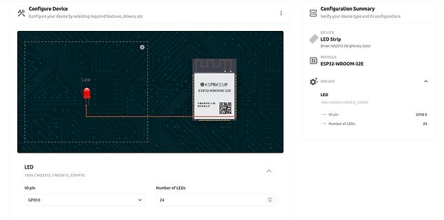
Configuration Summary
Verify your device type and its configurations
DEVICE
LED Strip
Driver: WS 2812 | Brightness, Color
MODULE
ESP32-WROOM-32E
DRIVER
LED
1000 / WS 2812 / WS 2812 _CONFIG
IO pin GPIO 0
Number of LEDs 24
in
„Neues RTL-SDR-Dongle, Matter-Gerätegenerator von ESP32 und andere Funknachrichten“
·
HF, Funk und Felder
·
22.08.2023 10:51
·
Screenshots
Bild
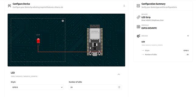
WROOM
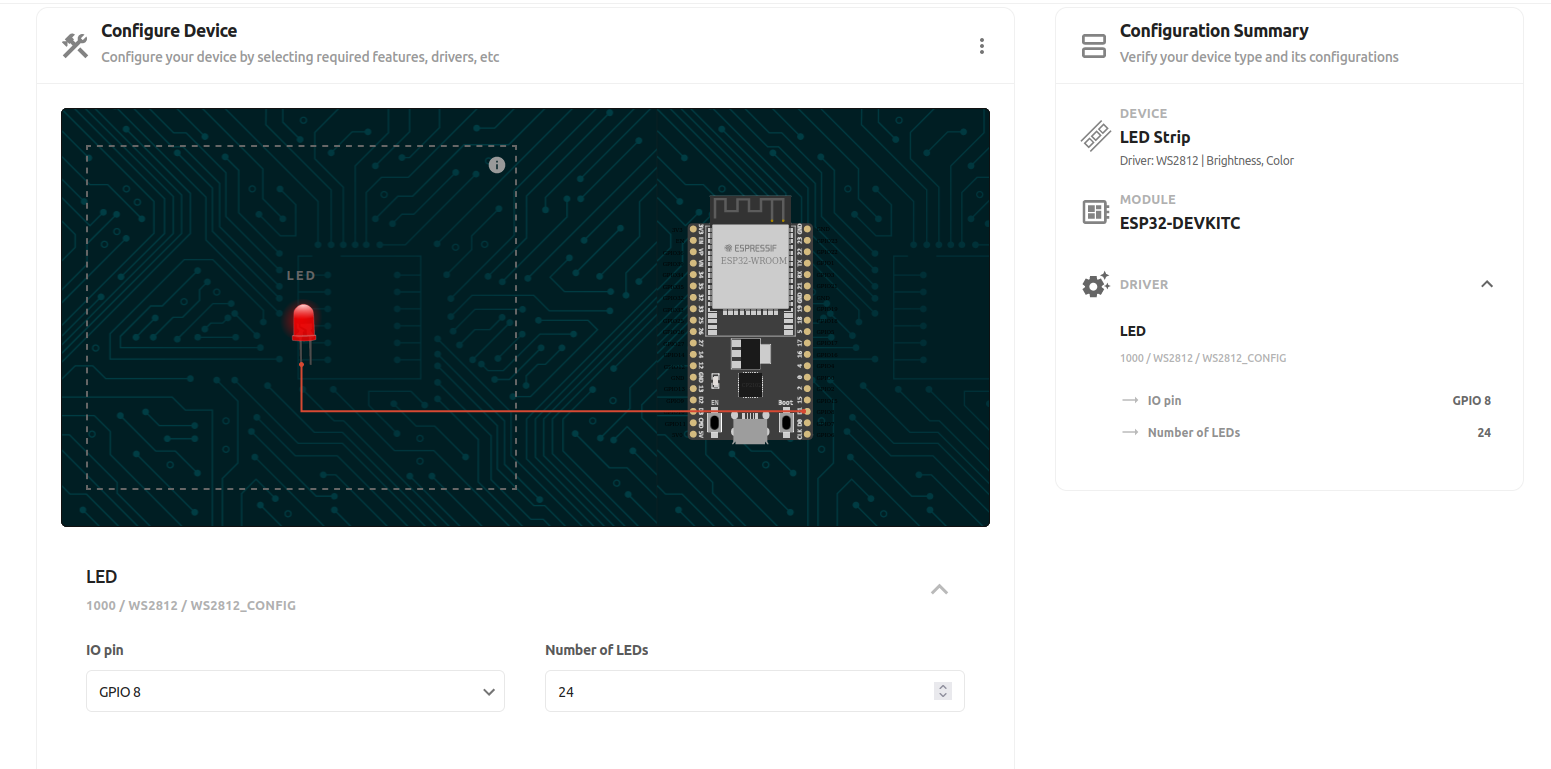
Configuration Summary
Verify your device type and its configurations
DEVICE
LED Strip
Driver: WS 2812 | Brightness, Color
MODULE
ESP32-DEVKITC
DRIVER
LED
1000 / WS 2812 / WS 2812 _CONFIG
IO pin
GPIO 8
Number of LEDs
24
in
„Neues RTL-SDR-Dongle, Matter-Gerätegenerator von ESP32 und andere Funknachrichten“
·
HF, Funk und Felder
·
22.08.2023 10:51
·
Screenshots
Bild
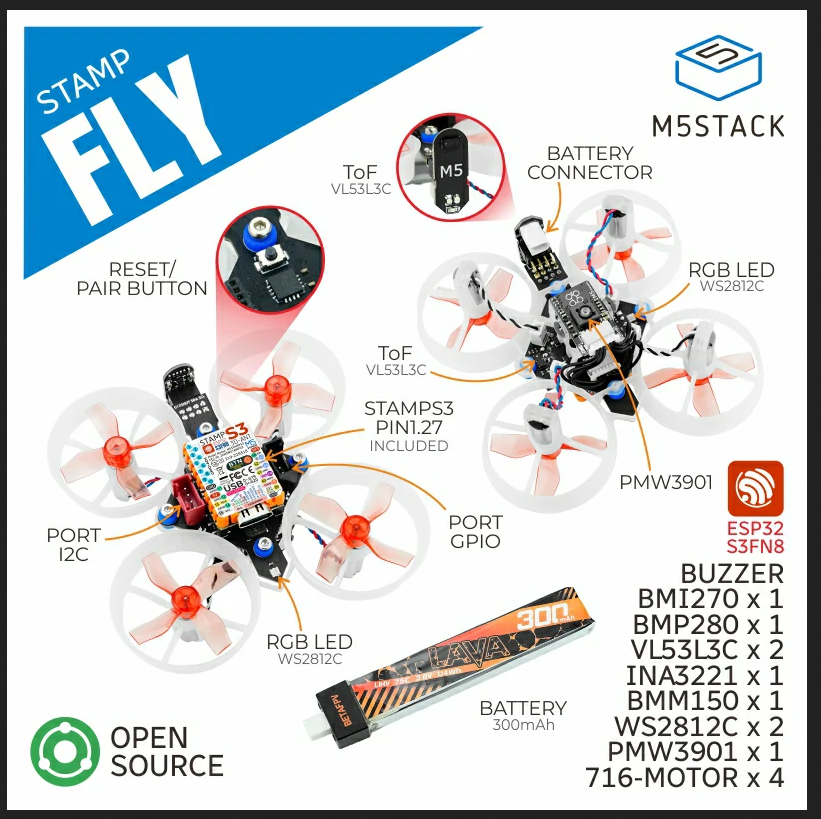
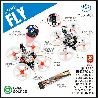
STAMP FLY M5STACK RESET/ PAIR BUTTON ToF VL53L3C BATTERY CONNECTOR RGB LED WS 2812 C ToF VL53L3C STAMPS3 PIN1.27 INCLUDED PORT I2C PORT GPIO RGB LED WS 2812 C PMW3901 BATTERY 300mAh ESP32 S3FN8 BUZZER BMI270 x 1 BMP280 x 1 VL53L3C x 2 INA3221 x 1 ISM150 x 1 WS 2812 C x 2 PMW3901 x 1
in
„Bauteil-Roundup: Drohnenkit bis Piezoputzanlage“
·
Mikrocontroller und Digitale Elektronik
·
09.09.2024 19:19
·
Sonstiges
Bild
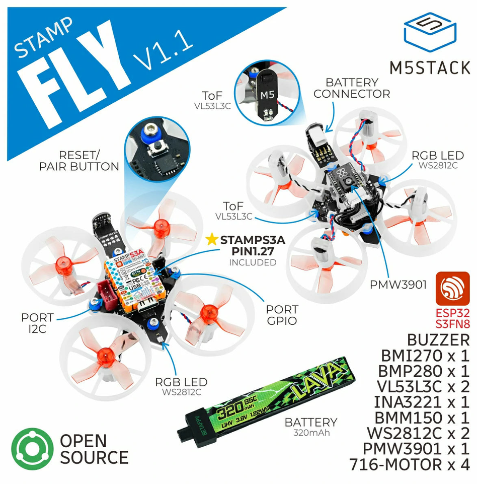
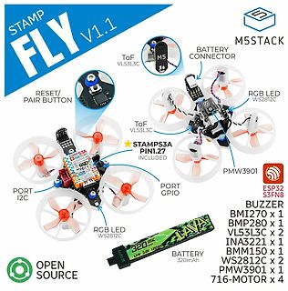
STAMP FLY V1.1 M5STACK RESET/ PAIR BUTTON ToF VL53L3C BATTERY CONNECTOR RGB LED WS 2812 C ToF VL53L3C STAMPS3A PIN1.27 INCLUDED PORT I2C PORT GPIO RGB LED WS 2812 C PMW3901 BUZZER BMI270 x 1 BMP280 x 1 VL53L3C x 2 INA3221 x 1 BMM150 x 1 WS 2812 C x 2 PMW3901 x 1 716-MOTOR x 4 LAVA 320mAh
in
„Neue Bauteile: Hochgeschwindigkeitsfunk, Löttechnik und die Rückkehr der QWERTZ-Tastatur“
·
Mikrocontroller und Digitale Elektronik
·
07.08.2026 06:59
·
Sonstiges
Bild
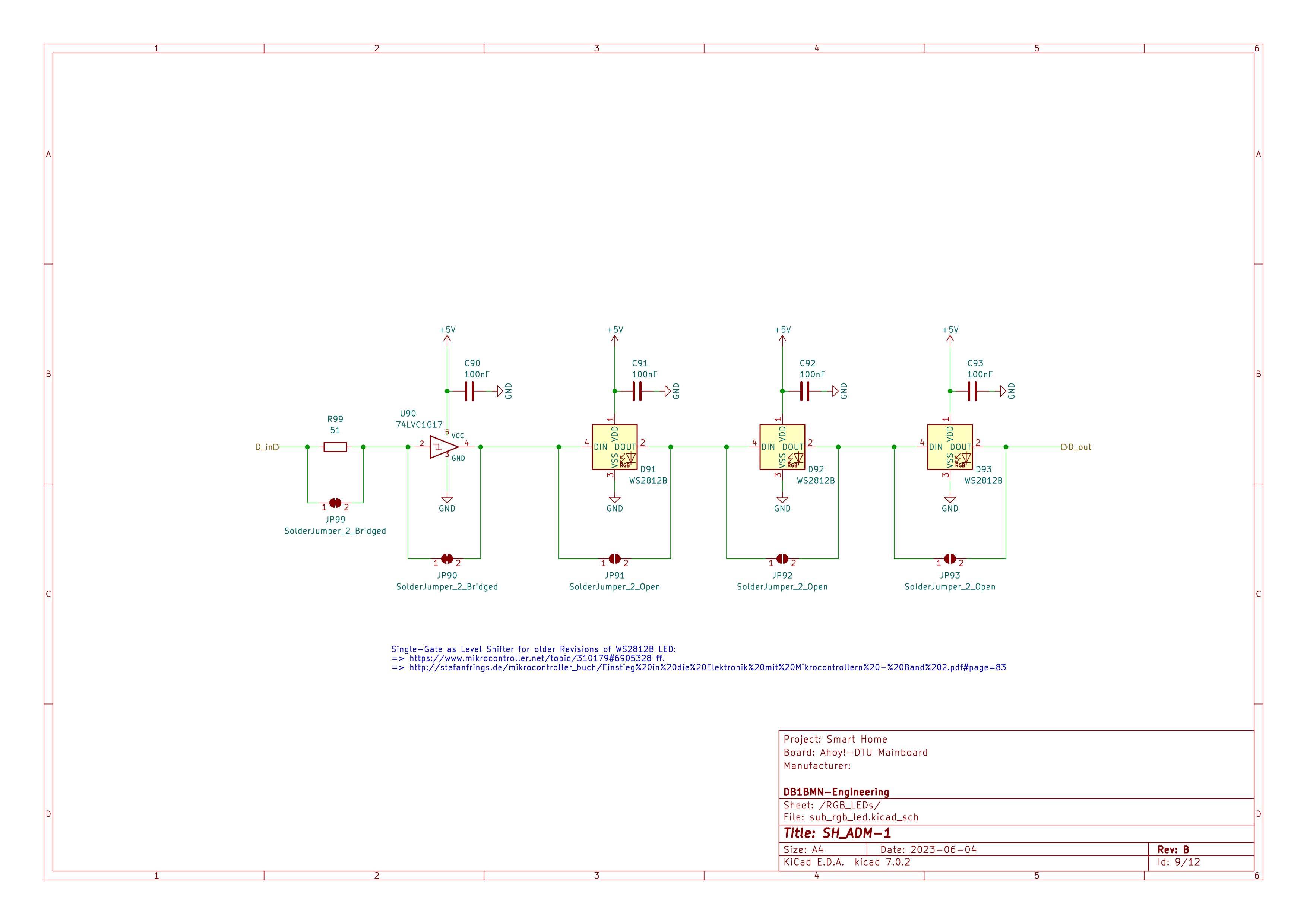
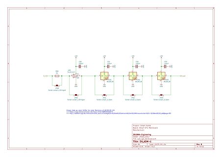
R99, S1, U90 74LVC1G17, D_in, GND, +5V, C90 100nF, JP99 SolderJumper_2_Bridged, JP90, C91 100nF, D91 WS 2812 B, DIN, DOUT, JP91 SolderJumper_2_Open, GND, C92 100nF, D92 WS 2812 B, DIN, DOUT, JP92 SolderJumper_2_Open, C93 100nF, D93 WS 2812 B, DIN, DOUT, D_out, Project: Smart Home, Board: Anydot-DTU Mainboard
in
„Wortuhr Dioden Multiplex entstören“
·
Analoge Elektronik und Schaltungstechnik
·
19.06.2026 16:20
·
Schaltpläne
/* * Copyright 2012 Alan Burlison, alan@bleaklow.com. All rights reserved. * Use is subject to license terms. */ /* * WS2811 RGB LED driver. */ #ifndef WS2811_h #define WS2811_h // RGB value structure. typedef struct __attribute__ ((__packed__)) { uint8_t r; uint8_t g; uint8_t b; } RGB_t; #ifndef ARRAYLEN #define ARRAYLEN(A) (sizeof(A) / sizeof(A[0])) #endif /* * Inline asm macro to output 24-bit RGB value in (G,R,B) order, MSBit first. * 0 bits are 250ns hi, 1000ns lo, 1 bits are 1000ns hi, 250ns lo. * r18 = red byte to be output * r19 = green byte to be output * r20 = blue byte to be output * r26
in
„Portierung ASM“
·
Mikrocontroller und Digitale Elektronik
·
25.03.2013 09:58
/* * ws 2812 .s * * Created: 12.12.2012 01:09:32 * Author: adrock */ #include <avr/io.h> #include "asmdefs.h" #define F_OUT 800000 #define F_CPU 16000000 #define CNT_TOTAL ((F_CPU/F_OUT)-1) #define CNT_LOW ((F_CPU/F_OUT)/3-1) #define CNT_HIGH (((F_CPU/F_OUT)*2)/3-1) .global WS _init .global WS _put WS _init: cbi _SFR_IO_ADDR(PORTB), PB1 sbi _SFR_IO_ADDR(DDRB), PB1 ldi r24, (1<<COM0B1)|(1<<WGM01)|(1<<WGM00) STORE TCCR0A, r24 ldi r24, CNT_TOTAL STORE OCR0A, r24 ret WS _put: movw
in
„Serielle Ansteuerung / Protokoll WS2812 RGB LED“
·
Mikrocontroller und Digitale Elektronik
·
16.12.2012 03:27
#include <avr/interrupt.h> #include <stdbool.h> #include "ws 2812 _config.h" #include "ws 2812 .h" static bool _stripeModeChangeRequest; static bool _stripeDecoChangeRequest; static uint16_t _numOfPixel; static uint8_t _dataPin; static uint8_t _dataPort; void WS 2818
in
„WS2812b LED-streifen aktualisiert sich erst nach zweitem aufruf“
·
Mikrocontroller und Digitale Elektronik
·
17.04.2020 09:07
#ifndef WS 2818_H_ #define WS 2818_H_ #include <stdint.h> #include <stdbool.h> #include "ws 2812 _config.h" void WS 2818(volatile uint8_t* ddr, uint8_t ddrNewSate, volatile uint8_t* port, uint8_t portNewState, uint8
in
„WS2812b LED-streifen aktualisiert sich erst nach zweitem aufruf“
·
Mikrocontroller und Digitale Elektronik
·
17.04.2020 09:07
// write GRB data to WS 2812 LED string void ws 2812 _write(uint8_t *p_data, uint16_t cnt, volatile uint8_t *port, uint8_t mask);
in
„Frage zu IR-Remote+LED-Strips an AVR“
·
Mikrocontroller und Digitale Elektronik
·
22.11.2020 11:00
include <avr/power.h> #endif int i=0; #define PIN 9 // Hier wird angegeben, an welchem digitalen Pin die WS 2812 LEDs bzw. NeoPixel angeschlossen sind #define NUMPIXELS 40 // Hier wird die Anzahl der angeschlossenen WS 2812 LEDs bzw. NeoPixel angegeben Adafruit_NeoPixel pixels = Adafruit_NeoPixel(NUMPIXELS,
in
„LED Uhr mit RTC braucht Taster“
·
Mikrocontroller und Digitale Elektronik
·
08.07.2021 12:29
include <avr/power.h> #endif int i=0; #define PIN 9 // Hier wird angegeben, an welchem digitalen Pin die WS 2812 LEDs bzw. NeoPixel angeschlossen sind #define NUMPIXELS 40 // Hier wird die Anzahl der angeschlossenen WS 2812 LEDs bzw. NeoPixel angegeben Adafruit_NeoPixel pixels = Adafruit_NeoPixel(NUMPIXELS,
in
„LED Uhr mit RTC braucht Taster“
·
Mikrocontroller und Digitale Elektronik
·
08.07.2021 14:22
= 1; DDRB|=_BV(ws 2812 _pin); uint16_t i; for(i=MAXPIX; i>0; i--) { led[i-1].r=0;led[i-1].g=0;led[i-1].b=0; } DDRD &= ~((1<<PIND2)|(1<<PIND3)|(1<<PIND4)); //d2 d3 d4 PORTD |= (1<<PIND2)|(1<<PIND3)|(1<<PIND4); // Pull ups
in
„Kann mit Light WS2812 nicht mehr als 128 LEDs ansteuern“
·
Mikrocontroller und Digitale Elektronik
·
07.12.2016 20:06
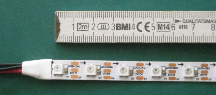
Bild
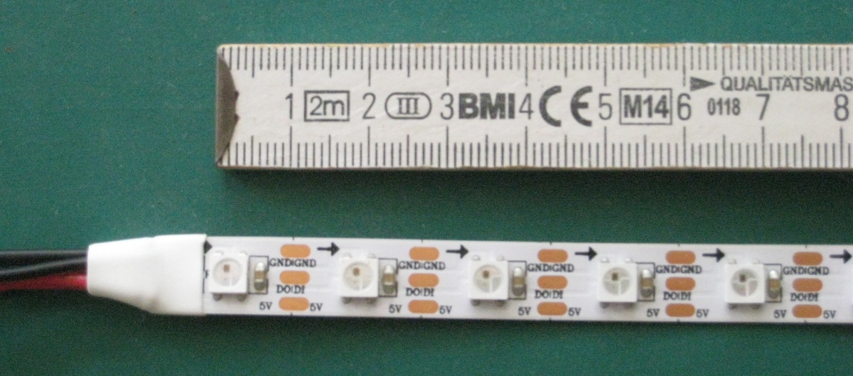
1 2m 2 III 3 BMI 4 CE 5 M14 6 0118 7 8 GND GND GND DO DI DO DI DO DI DO DI DO DI 5V 5V 5V
in
„[V] LED-Stripes: RGB WS2812 bzw. weiß, jeweils 60 LED/m“
·
Markt
·
13.05.2023 13:32
·
Fotos
button_init... timer2_init... wpsbutton_init... Version: 2.9.5 Hardware: STM32F103 Display: WC12h LEDs: WS 2812 GRB Welcome to WordClock Logger! ---------------------------- irmp_init... power_init... power_init() called power_on... switching power on delay_init... board_led_init... button_init... timer2_init... wpsbutton_init... Version: 2.9.5 Hardware: STM32F103 Display: WC12h LEDs: WS 2812 GRB rtc is online eeprom is online ws 2812 : no external pullup detected eeprom is online current eeprom version: 0x00020900 reading ir codes from eeprom DFPLAYER LOGGER ESP8266 LOGGER read rtc: Tu
in
„WordClock mit WS2812“
·
Projekte & Code
·
19.03.2019 22:33
include "uart/uart.h" #include "timer/timer.h" #include "time/time.h" #include "clock/clock.h" #include "ws 2812 /ws 2812 .h" #include "io/io.h" #define WS 2818_DATA_PIN PIND2 #define WS 2818_MAX_PIXEL 110 #define WS 2818_SEND_DATA_DELAY 50 #define UART_MAXSTRLEN 12 #define BUTTON_DEBOUNCETIME 3 volatile uint8_t
in
„WS2812b LED-streifen aktualisiert sich erst nach zweitem aufruf“
·
Mikrocontroller und Digitale Elektronik
·
17.04.2020 10:17
'3-Farben-fader mit WS 2812 b $regfile = "attiny13a.dat" $crystal = 9600000 $hwstack = 16 $swstack = 16 $framesize = 7 $lib "Rainbow.lib" 'implementierung $external Ws 2812 b 'Driver Declare sub BOW_INIT() Declare Sub Bow_reset() Declare Sub Bow_clear(byval Set_direct As Byte) Declare sub BOW_Select(Bylabel WS 2812 b_Channel as Word) Declare Sub Bow_setcolor(byval Lednr As Word , Byval Color As Long , Byval Set_direct As Byte) Const Send = 1 Const Nosend = 0 Const Nosettablecolor = 1 Const Noswap = 1 Const Norotate
in
„3x LED-PWM-Faden“
·
Mikrocontroller und Digitale Elektronik
·
30.08.2014 11:10
XTAL_FREQ 32000000 #include <XC.h> #include <stdio.h> #include <stdlib.h> #include <stdint.h> #include "WS 2812 .h" void main(void) { unsigned char rgb_data[]={0xFF,0x00,0x00, 0x00,0xFF,0x00 ,0x00,0x00,0xFF,}; int angle; OSCCONbits.SPLLEN=1; // 4x PLL Is enabled OSCCONbits.IRCF=0b1110; // 8 MHz or 32 MHz HF
in
„[ASM & C] PIC12/PIC18/PIC24 WS2812 SPI Library“
·
Projekte & Code
·
07.09.2014 22:42
at 16MHz */ #include <util/delay.h> #include <avr/io.h> #include <avr/interrupt.h> #include "light_ws 2812 .h" #define MAXPIX 4 #define COLORLENGTH (50) #define FADE (256/COLORLENGTH) struct cRGB colors[8]; struct cRGB led[MAXPIX]; int main(void) { uint8_t j = 1; uint8_t k = 1; DDRB|=_BV(ws 2812 _pin); uint8
in
„Neopixel Attiny85 Makefile Probleme“
·
Mikrocontroller und Digitale Elektronik
·
06.10.2017 17:08
at 16MHz */ #include <util/delay.h> #include <avr/io.h> #include <avr/interrupt.h> #include "light_ws 2812 .h" #define MAXPIX 30 #define COLORLENGTH MAXPIX/2 #define FADE 256/COLORLENGTH struct cRGB colors[8]; struct cRGB led[MAXPIX]; int main(void) { uint8_t j = 1; uint8_t k = 1; DDRB|=_BV(ws 2812 _pin)
in
„Kann mit Light WS2812 nicht mehr als 128 LEDs ansteuern“
·
Mikrocontroller und Digitale Elektronik
·
07.12.2016 12:12
avr/eeprom.h> #include <avr/io.h> #define EESIZE (1+E2END) #include "Lichterkette.h" #include "light_ws 2812 .h" #include "ws 2812 _config.h" typedef struct { const uint8_t numLED; const uint8_t colorWhiteR; const uint8_t colorWhiteG; const uint8_t colorWhiteB; const uint8_t colorOrangeR; const uint8_t colorOrangeG
in
„Deadlock in Übersetzungsdurchgang“
·
Mikrocontroller und Digitale Elektronik
·
10.06.2015 11:16
<avr/io.h> #include <avr/eeprom.h> #include <stdlib.h> #include <avr/interrupt.h> #include "light_ws 2812 .h" #include "irmpconfig.h" #include "irmp.h" //defines LEDs / Programme #define MAXPIX 106 #define COLORLENGTH MAXPIX/2 #define FADE 256/COLORLENGTH #define P_Nothing 0 #define P_ColorPix 1 #define
in
„Lightweight WS2811/WS2812 Library“
·
Mikrocontroller und Digitale Elektronik
·
31.12.2016 17:27
HAS ONLY GOT THE ADUIO VISUALIZER MODE USING THE MSGEQ7 FOR OTHER MODES SEE THE "RGBStripe_Control_WS 2812 .ino SKETCH **/ #define USES_POTENTIOMETER 0 // SET THIS TO "1" IF YOU ARE USING POTENTIOMETER FOR BRIGHTNESS CONTROL! #define POT_BRIGHTNESS A2 #define LED_DATA 6 #define NUM_LEDS 300 #define BRIGHTNESS
in
„MSGEQ7 zeigt durchgängig einen Wert unabhängig vom Audiosignal an“
·
Mikrocontroller und Digitale Elektronik
·
20.03.2020 13:37
#include "WS 2812 .h" #define numleds 2 uint8_t pixel[numleds*3]; #define PWM_CT1_B 10 //OC1B #define PWM_CT2_B 3 //OC2B #define Vout A1 #define Vin A0 #define maxpwm 4*248 #define minpwm 0 float V_set_in = 17.0; float
in
„Hab meinen MPP(T) akkulader probiert :)“
·
Mikrocontroller und Digitale Elektronik
·
16.10.2022 15:33
, active-low. * LED_TYPE 1 -> SuperMini Plus/V2: addressable WS 2812 B NeoPixel on GPIO8. * */ #include <Arduino.h> #include <NimBLEDevice.h> #ifndef LED_TYPE #define LED_TYPE 0 #endif #if LED_TYPE == 1 #include <FastLED.h> #endif // -------------------------------
in
„esp32 c3 BLE to ws2812 + softseriel out“
·
Offtopic
·
02.09.2026 18:52
Connector 17 A1 GPA4 26 12 28 1 MISO +5 2 +5V R9 A2 GPA5 27 11 27 Solder Jumper to run 1K GPA6 10 26 WS 2812 b with 5V USB 3 4 18 RESET GPA7 28 9 25 power (only in special cases) SCK MOSI 8 24 5 6 20 INTA 7 23 RESET GND 19 INTB GPB0 1 6 22 2 14 GPB1 3 5 21 11 NC GPB2 4 4 20 NC GPB3 3 19 DSP-NEXTION GPB4
in
„ATMEGA32U4 Schaltplan“
·
Mikrocontroller und Digitale Elektronik
·
13.03.2019 16:54
gives a pulse width of 444nS which is well within spec for the SK6812 but is probably too long for the WS 2812 which needs a 350ns pulse for T0H This WS 2811B library is free software: you can redistribute it and/or modify it under the terms of the GNU Lesser General Public License as published by the Free
in
„STM32 Bluepill -> SK6812 (auf Basis von WS2812B Lib)“
·
Projekte & Code
·
29.10.2023 08:18
B 1 32 L298_IN4 R4 B L298_ENB 2(PCINT19/OC2B/INT1)PD3 PD2(INT0/PCINT18)31 TX 10K ABSTANDSENSOR C2 WS 2812 _LED 3(PCINT20/XCK/T0)PD4 PD1(TXD/PCINT17) 30 RESET Header-Male-2.54_2x5 22pF GND 4GND PD0(RXD/PCINT16) 29 RX 5V 1 2 SCL 5V 5VCC PC6(RESET#/PCINT14) 28 3 1 GND 3 4 SDA 3 2 GND 6GND PC5(ADC5/SCL/PCINT13
in
„atmega328 - arduino bootloader flashen - doppelt belegte Pins“
·
Platinen
·
23.04.2020 23:44
Bild
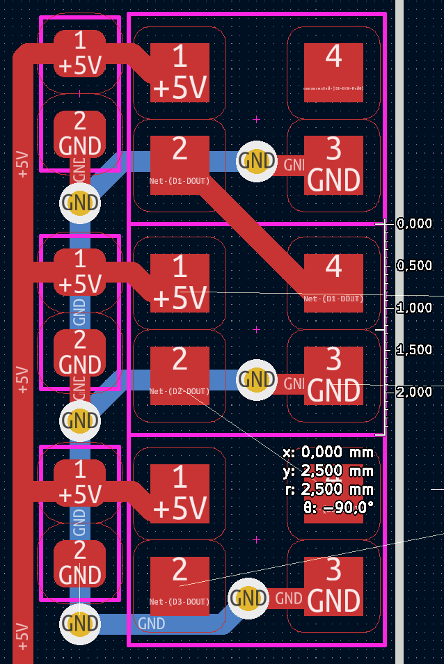
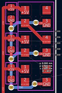
1 +5V 2 GND 3 GND 4 1 +5V 2 GND 3 GND 4 1 +5V 2 GND 3 GND 4 1 +5V 2 GND 3 GND 4 GND Net-(D1-DOUT) GND Net-(D2-DOUT) GND Net-(D3-DOUT) GND x: 0,000 mm y: 2,500 mm r: 2,500 mm $\theta$: -90,0°
in
„Suche mini-kleine PCB mit WS2812-kompatiblen LEDs“
·
Mikrocontroller und Digitale Elektronik
·
26.01.2024 14:58
·
Layouts
/* * ws 2812 test.c * * Created: 12.12.2012 00:02:22 * Author: adrock */ #define F_CPU 16000000 #include <avr/io.h> #include <util/delay.h> extern void WS _init(void); extern void WS _put(uint8_t *D, uint16_t Num
in
„Serielle Ansteuerung / Protokoll WS2812 RGB LED“
·
Mikrocontroller und Digitale Elektronik
·
16.12.2012 03:26
/* * Ws IntSpi.c * * Created: 02.11.2018 16:32:20 * Author: Thomas */ #include <stdbool.h> #include "sam.h" #include "clocks.h" #include "IO.h" #include "Ws 2812 Spi.h" #define RAM_FUNC __attribute__ ((long_call
in
„ATSAM WS2812B?“
·
Mikrocontroller und Digitale Elektronik
·
29.03.2019 19:46
#include <CharacterEncoding.h> #include <ShiftDisplay.h> #include <Adafruit_NeoPixel.h> #include <RTClib.h> #include <Wire.h> #include <boarddefs.h> #include <IRremote.h> #include <IRremoteInt.h> #include <ir_Lego_PF_BitStreamEncoder.h> #define PIXEL_PIN 9 // Digital IO pin connected to the NeoPixels. #define PIXEL_COUNT 60 // Parameter 1 = number of pixels in strip, neopixel stick has 8 // Parameter 2 = pin number (most are valid) // Parameter 3 = pixel type flags, add together as needed: // NEO_RGB Pixels are wired for RGB bitstream // NEO_GRB Pixels are wired for GRB bitstream, correct for neopixel
in
„WS2811 und 74HC595 Zusammen an Arduino steuren“
·
Mikrocontroller und Digitale Elektronik
·
19.12.2017 16:58
/** * NeoClock * * Clock using 60 WS 2812 B/Neopixel LEDs and DS3231 RTC * * Libraries needed: * * Adafruit NeoPixel (Library Manager) - Phil Burgess / Paint Your Dragon for Adafruit Industries - LGPL3 * * Rtc by Makuna (Library Manager)
in
„LED Uhr mit RTC braucht Taster“
·
Mikrocontroller und Digitale Elektronik
·
08.07.2021 14:24
Bild
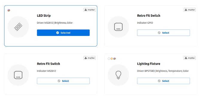
matter LED Strip Driver: WS 2812 | Brightness, Color Selected Retro Fit Switch Indicator: GPIO Select matter Retro Fit Switch Indicator: WS 2812 Select matter Lighting Fixture Driver: BP5758D | Brightness, Temperature, Color Select
in
„Neues RTL-SDR-Dongle, Matter-Gerätegenerator von ESP32 und andere Funknachrichten“
·
HF, Funk und Felder
·
22.08.2023 10:51
·
Screenshots
#include <util/delay.h> #include <avr/io.h> #include <avr/interrupt.h> #include "light_ws 2812 .h" #define F_CPU 8000000UL #define ANZAHL_SPALTEN 24 #define ANZAHL_ZEILEN 24 #define ANZAHL_LEDS (ANZAHL_SPALTEN * ANZAHL_ZEILEN) #define UP 1 #define DOWN 0 struct cRGBW led[ANZAHL_LEDS]; uint16
in
„LED-Matrix mit light_ws2812-library; Ansteuerungsgeschwindigkeit“
·
Mikrocontroller und Digitale Elektronik
·
15.12.2018 12:31
Bild
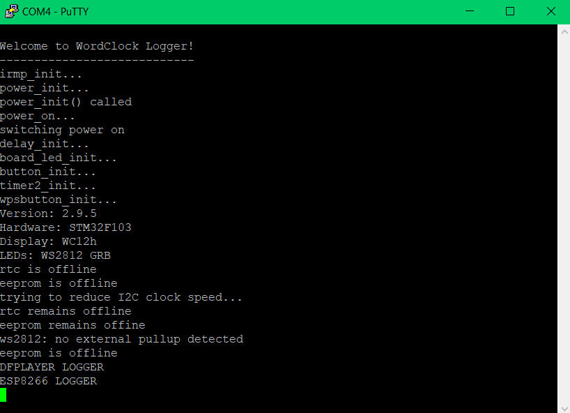
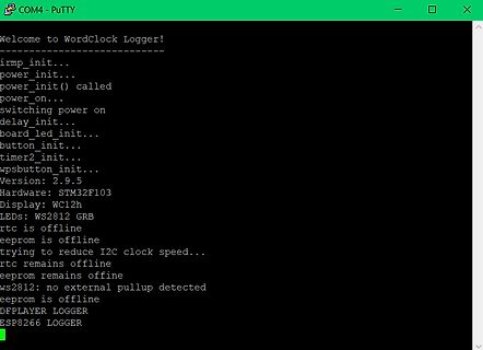
button_init...
timer2_init...
wpsbutton_init...
Version: 2.9.5
Hardware: STM32F103
Display: WC12h
LEDs: WS 2812 GRB
rtc is offline
eeprom is offline
trying to reduce I2C clock speed...
rtc remains offline
eeprom remains offline
ws 2812 : no external pullup detected
eeprom is offline
DFPLAYER LOGGER
ESP8266 LOGGER
in
„WordClock mit WS2812“
·
Projekte & Code
·
23.08.2025 14:56
·
Screenshots
Bild
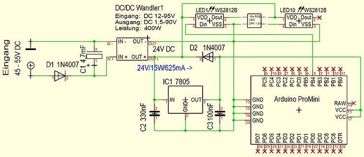
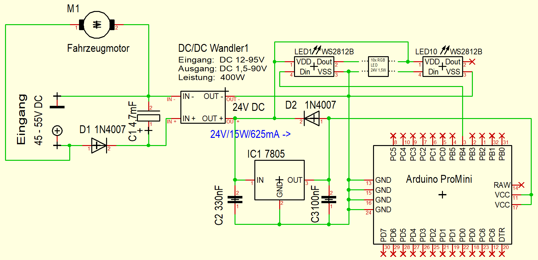
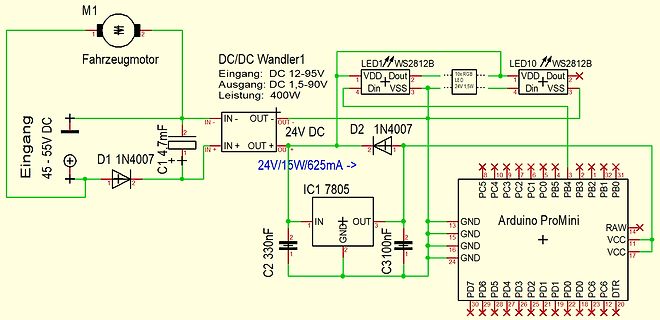
M1 Fahrzeugmotor, DC/DC Wandler1, Eingang: DC 12-95V, Ausgang: DC 1,5-90V, Leistung: 400W, LED1 WS 2812 B, LED10 WS 2812 B, 24V 1,5W, Eingang 45-55V DC, D1 1N407, C1 4,7mF, 24V/15W/625mA, D2 1N407, IC1 7805, C2 330nF, C3 100nF, Arduino ProMini, PC5 bis PC0, PB5 bis PB1, PB0, RAW, VCC, DDR, DT, PD0 bis
in
„DCDC Wandler sterben - Schutzmaßnahmen?“
·
Analoge Elektronik und Schaltungstechnik
·
22.11.2025 12:26
·
Schaltpläne
button_init... timer2_init... wpsbutton_init... Version: 2.9.4 Hardware: STM32F103 Display: WC12h LEDs: WS 2812 GRB rtc is online eeprom is online ws 2812 : external pullup detected eeprom is online current eeprom version: 0x00020900 reading ir codes from eeprom DFPLAYER LOGGER ESP8266 LOGGER read rtc: Su 2000
in
„WordClock mit WS2812“
·
Projekte & Code
·
06.01.2019 00:03
Heartbeat Heartbeat AREF PC7:0 PF0 LCD Atmega128 DRV5033 PA7:0 I²C MAX520 Pinheader LM4040 + Buffer WS 2812 PG0 PB7:0 CAT5259 PG4 ADS7828 RV4162 Backup Battery ICSP M24C64 JTAG PF7:0 AREF PG4 RS232/UART UART0 I²C MAX520 LM4040 + MAX3232 Buffer Atmega128L PCF8563 Backup Battery PA7:0 M24C64 EC11 Taster PC7:0 LCD SPI Heartbeat PG1 WS 2812 PG0 ADS7844
in
„Dev-Kit machen?“
·
Mikrocontroller und Digitale Elektronik
·
14.07.2020 00:05
button_init... timer2_init... wpsbutton_init... Version: 2.9.5 Hardware: STM32F103 Display: WC12h LEDs: WS 2812 GRB rtc is online eeprom is online ws 2812 : external pullup detected eeprom is online current eeprom version: 0x00020900 reading ir codes from eeprom DFPLAYER LOGGER ESP8266 LOGGER read rtc: Su 2000
in
„WordClock mit WS2812“
·
Projekte & Code
·
17.04.2020 08:30
Bild
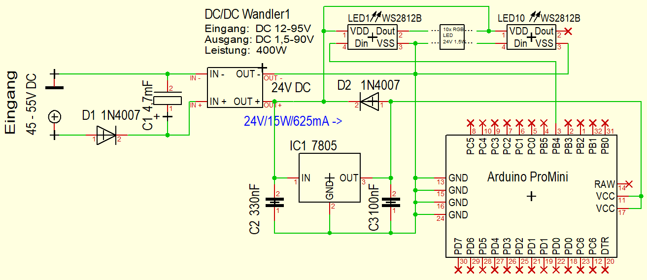
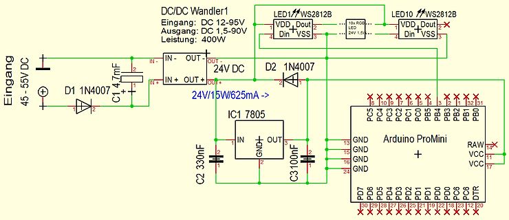
DC/DC Wandler1 Eingang: DC 12-95V Ausgang: DC 1,5-90V Leistung: 400W LED1 WS 2812 B LED10 WS 2812 B VDD Dout VSS Din 24V 1,5V Eingang 45-55V DC D1 1N4007 C1 4,7mF IN- OUT- OUT+ IN+ OUT+ 24V DC D2 1N4007 IC1 7805 24V/15W/625mA -> C2 330nF C3 100nF IN GND OUT GND GND GND Arduino ProMini
in
„DCDC Wandler sterben - Schutzmaßnahmen?“
·
Analoge Elektronik und Schaltungstechnik
·
22.11.2025 11:05
·
Schaltpläne
Bild
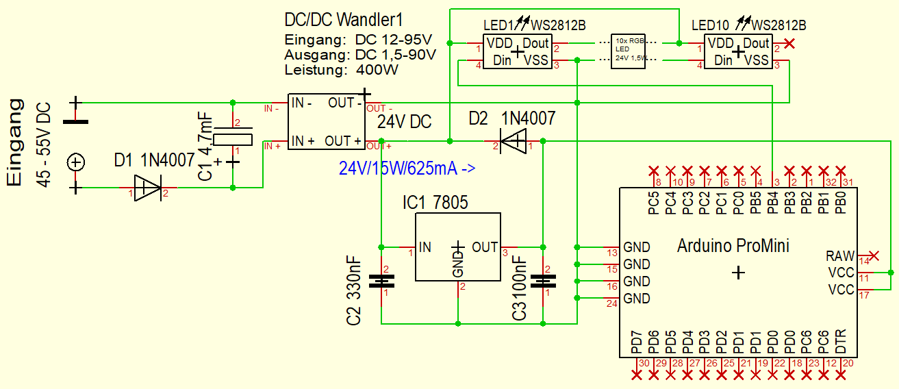
DC/DC Wandler1 Eingang: DC 12-95V Ausgang: DC 1,5-90V Leistung: 400W LED1 WS 2812 B LED10 WS 2812 B 24V 1,5W VDD Dout Din VSS Eingang 45-55V DC D1 1N4007 C1 4,7mF IN- OUT- 24V DC IN+ OUT+ D2 1N4007 24V/15W/625mA -> IC1 7805 IN GND OUT C2 330nF C3 100nF Arduino ProMini GND GND GND
in
„DCDC Wandler sterben - Schutzmaßnahmen?“
·
Analoge Elektronik und Schaltungstechnik
·
22.11.2025 11:19
·
Schaltpläne
button_init... timer2_init... wpsbutton_init... Version: 2.9.1 Hardware: STM32F103 Display: WC24h LEDs: WS 2812 GRB rtc is online eeprom is online ws 2812 : no external pullup detected eeprom is online current eeprom version: 0x00020900 reading ir codes from eeprom DFPLAYER LOGGER ESP8266 LOGGER read rtc: We
in
„WordClock mit WS2812“
·
Projekte & Code
·
09.05.2018 13:50
voneinander abhängiges Bewegungsschema vorwärts-rückwärts-Drehung rechts-Drehung links - Steuern von einem WS 2812 B RGB LED Ring mit 24-32 LEDs - Bedienung über Balkenmenu auf SH1106-OLED-Display 128 x 64 Pixel - Menu-Steuerung über Drehgeber - Menu viersprachig (DE, EN, FR, ES) Alle Einstellungen bei Veränderung
in
„Unterstützung gesucht, Micropython & Platinenlayout“
·
Markt
·
02.02.2023 13:20

 Bild
Bild
 Bild
Bild
 Bild
Bild
 Bild
Bild
 Bild
Bild
 Bild
Bild
 Bild
Bild
 Bild
Bild
 Bild
Bild
 Bild
Bild
 Bild
Bild
 Bild
Bild