-
Datei
xFB_switch.h
case (fb_0): lgw(4,10,"Stopp "); egg_off; egg_state=egg_state_aus; cookingtime=0; pwm_sound_on(110); soundtimer=2; egg_timer_ct=0; break; case (fb_1): lgw(4,1,"Aufheizen Weichei "); cookingtime=280; egg_on; egg_state=egg_state_aufheizen; pwm_sound_on(110); soundtimer=2; egg_timer_ct=
-
PDF
Book_of_Knowledge_german.pdf
PWM- PWM- ReferenzV VS Komparatorlip-Flop-Schaltung REF+ V = I I spannung VFB A1 S S R Trenn- - schalter R Fehler- VOUT 1 verstärker S Rückführung s R2 Abb. 1.41: Blockschaltbild eines Strommodus-PWM-Kontrollers
in „Eingangsfilter DC-DC-Wandler - mal wieder“ · Analoge Elektronik und Schaltungstechnik ·
-
PDF
RECOM_de_Buch.pdf
PWM- PWM- ReferenzV VS Komparatorlip-Flop-Schaltung REF+ V = I I spannung VFB A1 S S R Trenn- - schalter R Fehler- VOUT 1 verstärker S Rückführung s R2 Abb. 1.41: Blockschaltbild eines Strommodus-PWM-Kontrollers
in „Schaltnetzteil Grundlage“ · Analoge Elektronik und Schaltungstechnik ·
-
 Bild
Bild
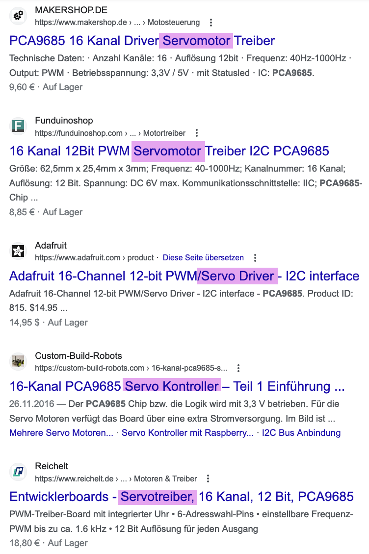
Suchergebnisse für PCA9685 Servomotor Treiber
Servomotor Treiber Technische Daten: Anzahl Kanäle: 16 • Auflösung 12bit • Frequenz: 40Hz-1000Hz • Output: PWM • Betriebsspannung: 3,3V / 5V • mit Status LED • IC: PCA9685. 9,60 € • Auf Lager Funduinoshop 16 Kanal 12Bit PWM Servomotor Treiber I2C PCA9685 Größe: 62,5mm x 25,4mm x 3mm; Frequenz: 40-1000Hz; Kanalnummer
in „Arduino mit 7 Servos“ · Mikrocontroller und Digitale Elektronik · · Screenshots
-
Datei
Test_Tiny13.asm
;PWM-Test .include "tn13def.inc" .def TEMP1 = r16 .def SAVE_SREG = r17 .def PAUSE = r18 .def PWM = r19 .def LED = r20 .def DIR = r21 .org $000 rjmp RESET ;Reset-Vektor .org $003 rjmp TIMER1 ;Timer-Vektor
in „Verständnisfrage SRAM“ · Mikrocontroller und Digitale Elektronik ·
-
Datei
BASCOM.txt
$crystal = 9600000 $hwstack = 16 $swstack = 5 $framesize = 16 Config Portb.0 = Output 'Ausgang f?r PWM an PB0 Config Timer0 = Pwm , Compare A Pwm = Clear Down , Prescale = 1 Config 1wire = Portb.4 'hier ist der DS18S20 angeschlossen 'Dimensionierung der Variablen: Dim Variable1 As Byte Dim Variable2
in „Bascom vs. Assembler“ · Mikrocontroller und Digitale Elektronik ·
-
Datei
Timer3FastPWMMode.txt
******************************************** //*** Diese Methode startet den 16-Bit-timer3 im fast PWM Mode *** //*** Es muß die PWM-Intervalldauer und die länge *** //*** des initialen PWM-pulses angegeben werden. *** //**************************************************************** void start_16Bit_Timer3_In_FAST_PWM_Mode(short TOPValue,short startPWMInterval){ TCCR3B = TCCR1B & 0xF8; //CS10, CS11, CS12 auf 0 ==>timer erst abschalten //Einstellen des PWM-Modus (S.137) //Modus Nr.14 Fast PWM TOP=ICR3 TCCR3B = TCCR3B
in „FastPWM Mode auf AT90CAN128“ · Mikrocontroller und Digitale Elektronik ·
-
PDF
Si823x_-_AMP_ISOdriver.pdf
VOB NC 7 10 VOB VDDI 8 9 GNDB VDDI 8 9 GNDB Table 12. Si8231/4 PWM Input HS/LS Isolated Driver (SOIC-16) Pin Name Description 1 PWM PWM input. 2 NC No connection. 3 VDDI Input-side power supply terminal; connect to a source of 4.5 to 5.5 V. 4 GNDI Input-side ground
in „Si8223 - Highside/Lowside Treiber - normales Verhalten?“ · Mikrocontroller und Digitale Elektronik ·
-
PDF
ltc6812-1.pdf
Table 53. PWMRegister Group REGISTER RD/WR BIT 7 BIT 6 BIT 5 BIT 4 BIT 3 BIT 2 BIT 1 BIT 0 PWMR0 RD/WR PWM2[3] PWM2[2] PWM2[1] PWM2[0] PWM1[3] PWM1[2] PWM1[1] PWM1[0] PWMR1 RD/WR PWM4[3] PWM4[2] PWM4[1] PWM4[0] PWM3[3] PWM3[2] PWM3[1] PWM3[0] PWMR2 RD/WR PWM6[3] PWM6[2] PWM6[1] PWM6[0] PWM5[3] PWM5[2] PWM5[1] PWM5[0] PWMR3 RD/WR PWM8[3] PWM8[2] PWM8[1] PWM8[0] PWM7[3] PWM7[2] PWM7[1] PWM7[0] PWMR4 RD/WR PWM10[3] PWM10[2] PWM10[1] PWM10[0] PWM9[3] PWM9[2] PWM9[1] PWM9[0] PWMR5 RD/WR PWM12[3] PWM12[2] PWM12[1]
in „Differenzverstärker INA105“ · Analoge Elektronik und Schaltungstechnik ·
-
Datei
PID2.txt
y=Pwert+Isum; //Stellgrösse if(y>964) y=964; //Begrenzung auf 0...964 if(y<1) y=0; // ealt=e; set_pwm1_duty(y); //Ausgabe PWM T0IF=0; //Timer0 Interrupt-Flag löschen } /* #################################################################################################################### ############
in „PI-Regler (PIC) Problem mit Abtastzeit und Totzeit“ · Mikrocontroller und Digitale Elektronik ·
-
Datei
stromregler.c
shift_i 5 // 5 #define strom_mux 0x07 #define poti_mux 0x01 #define gain_kompensation 0x05 #define pwm_max 128 int saturation(int input, int limit_max, int limit_min); unsigned int stromregler(); int stromberechnung(); unsigned int filterung8(unsigned int input, unsigned int array[], unsigned char *position
in „Schon wieder volatile -_O“ · Mikrocontroller und Digitale Elektronik ·
-
Datei
PWM_PA0_Uvergleich-3.9khz-neu.asm
;ausgangsspannungsregelung nach stepdown ;pwm an atmega16 für 3,906 khz ;bei 4mhz taktfrequenz ;mit timer0 im fast pwm mode, 8 bit aufloesung ;pwm-signal liegt auf pb3 oc0 ;11.2.12 .include "m16def.inc" jmp reset ;führe reset aus jmp RESET ; Reset
in „Hilfe Ladereglung Atmega16 Assembler“ · Mikrocontroller und Digitale Elektronik ·
-
Datei
PWM_PA0_Uvergleich-3.9khz-IRQ.asm
;ausgangsspannungsregelung nach stepdown ;pwm an atmega16 für 3,906 khz ;bei 4mhz taktfrequenz ;mit timer0 im fast pwm mode, 8 bit aufloesung ;pwm-signal liegt auf pb3 oc0 ;12.2.12 .include "m16def.inc" ;.def v_panel = r14 ;Messwert PV-Spannung
in „Hilfe Ladereglung Atmega16 Assembler“ · Mikrocontroller und Digitale Elektronik ·
-
Datei
wiring.c
some functions won't // work there sei(); // on the ATmega168, timer 0 is also used for fast hardware pwm // (using phase-correct PWM would mean that timer 0 overflowed half as often // resulting in different millis() behavior on the ATmega8 and ATmega168) #if defined(TCCR0A) && defined(WGM01) sbi(TCCR0A
in „IRMP - Infrared Multi Protocol Decoder“ · Projekte & Code ·
-
Datei
Gyrosensor-Auslesen-Winkel_2-0.c
----------------------------------------------------------- int i=1; int abc=0; //Zählvariable für PWM-Berechnung int m=1; //Soll Schalterprellen verhindern Taster4 int n=1; //Soll Schalterprellen verhindern Taster5 double pwm=0; //Zahl die auf 487 addiert wird; bei OCR1A = 487 fängt Motor an zu drehen
in „Motorregelung“ · Mikrocontroller und Digitale Elektronik ·
-
Datei
AtMega328_timercounter.asm
ori temp1,(0<<OCIE0B | 0<<OCIE0A | 1<<TOIE0) sts TIMSK0,temp1 clr temp1 sts TCNT0,temp1 ret ;MODE 1 PWM-PhaseCorrect beide Channels nutzbar da Counter bis FF zählt mode1_t0_init: rcall A0_ch_en ;out aktivieren rcall B0_ch_en ;out aktivieren rcall A0_ch_load ;Zeitwert laden rcall B0_ch_load ;Zeitwert laden
in „Drehencoder in ASM Timer oder Interrupt“ · Projekte & Code ·
-
Datei
inverter.ino
/* */ #define PWM_CT2A 11 //OC2A #define PWM_CT2B 3 //OC2B #define maxpwm 120 void ct2_init() { pinMode(PWM_CT2A, OUTPUT); pinMode(PWM_CT2B, OUTPUT); TCCR2A = (1 << COM2B1) |(1 << COM2B0) | (1 << COM2A1) | (1 << WGM20); TCCR2B = (1 << CS20); // prescaler 0 OCR2A = 0; OCR2B = 255; // pwm value } void setup() { pinMode(LED_BUILTIN, OUTPUT); Serial.begin(115200); ct2_init(); } void setct(uint8_t data) { uint8_t ld = constrain(data,0,maxpwm); OCR2A = ld; OCR2B = 255-ld; // pwm value }
-
Datei
stepper.c
output as segment is loaded, just prior to the first step. spindle_set_speed(st.exec_segment->spindle_pwm); } else { // Segment buffer empty. Shutdown. st_go_idle(); // Ensure pwm is set properly upon completion of rate-controlled motion. if (st.exec_block->is_pwm_rate_adjusted) { spindle_set_speed(SPINDLE_PWM_OFF_VALUE
in „Problem mit Positionsrückmeldung bei GRBL“ · Mikrocontroller und Digitale Elektronik ·
-
PDF
Mikrocontroller-PIC18F2420.pdf
trigger event can be done. Conflicts may occur if both modules are using the same time base. Capture PWM (1) None Compare PWM (1) None PWM (1) Capture None PWM (1) Compare None PWM (1) PWM (1) Both PWMs will have the same frequency and update rate (TMR2 interrupt). Note 1: Includes standard and Enhanced
in „Spannungseinbruch beim Sampeln des Signals“ · Mikrocontroller und Digitale Elektronik ·
-
PDF
SSD1963_V014.pdf
the PWM configuration PWMF[7:0] : Set the PWM frequency in system clock (POR = 00000000) PWM signal frequency = PLL clock / (256 * (PWMF[7:0] + 1)) / 256 PWM[7:0] : Set the PWM duty cycle (POR = 00000000) PWM duty cycle = PWM[7:0] / 256 for DBC disable (0xD0] A0 = 0 If DBC enable (0xD0] A0 = 1, these parameter will be ignored Note : PWM always 0 if PWM[7:0] = 00h Figure 9-19: PWM signal Period = 1/ PWM Freq PWM PWM[7:0]/
in „SSD1963 Datenblatt“ · Mikrocontroller und Digitale Elektronik ·
-
PDF
SSD1963_Rev1.6.pdf
the PWM configuration PWMF[7:0] : Set the PWM frequency in system clock (POR = 00000000) PWM signal frequency = PLL clock / (256 * (PWMF[7:0] + 1)) / 256 PWM[7:0] : Set the PWM duty cycle (POR = 00000000) PWM duty cycle = PWM[7:0] / 256 for DBC disable (0xD0] A0 = 0 If DBC enable (0xD0] A0 = 1, these parameter will be ignored Note : PWM always 0 if PWM[7:0] = 00h Figure 9-19: PWM signal Period = 1/ PWM Freq PWM PWM[7:0]/
in „SSD1963 Datenblatt“ · Mikrocontroller und Digitale Elektronik ·
-
Datei
AVRootloader.asm
m88Pdef.inc" ; ATmega88P ;.include "m8Adef.inc" ; ATmega8A ;.include "m8def.inc" ; ATmega8 ;.include "pwm216def.inc" ; AT90PWM216 ;.include "pwm2Bdef.inc" ; AT90PWM2B ;.include "pwm2def.inc" ; AT90PWM2 ;.include "pwm316def.inc" ; AT90PWM316 ;.include "pwm324def.inc" ; AT90PWM324 ;.include "pwm3Bdef.inc" ; AT90PWM3B ;.include "pwm3def.inc" ; AT90PWM3 ;.include "tn13Adef.inc" ; ATtiny13A ATTENTION! small FLASH space, not all feature can be used ;.include "tn13def.inc" ; ATtiny13 ATTENTION! small FLASH space, not
-
PDF
miniat91.pdf
TCLK0_PA4 35 PA5 F 54 VDDCORE RXD0/NPCS3_PA5 34 PA6 2 1nF VDDCORE TXD0/PCK0_PA6 32 PA7 +3.3V 2 RTS0/PWM3_PA7 PA8 45 VDDIO CTS0/PWM3_PA8 31 PA9 58 VDDIO DRXD/NPCS1_PA9 30 PA10 +3.3V 18 VDDIO DTXD/NPCS2_PA10 29 +3.3V NPCS0/PWM0_PA11 28 PA11 +3.3V 59 VDDFLASH MISO/PWM1_PA12 27 PA12 R12 22 PA13 100K 0 R3
in „AT91SAM7 Mini Board“ · Mikrocontroller und Digitale Elektronik ·
-
Datei
fr_br_03.asm
Transistor für Rückfahrlicht (bzw Test-LED) gegen Masse ; und Programmiertaste gegen +5V ;PB3 (Pin 2); PWM-Ausgang bei Tiny12 Vorwärts (bei Tiny15 Rückwärts) ;PB4 (Pin 3); PWM-Ausgang bei Tiny12 Rückwärts (bei Tiny15 Vorwärts) ;Der Fahrtregler muss durch Programmierung der Parameter per Programmiertaste
in „Fehlererkennung für PWM aus RC-Fernsteuerung“ · Mikrocontroller und Digitale Elektronik ·
-
PDF
CMPS10.pdf
operation leave To enter the serial mode of operation To enter the PWM mode of operation the mode pin unconnected connect the mode pin to ground connect the select PWM pin to ground Data update frequency Updates of the tilt compensated heading occur at 75hz with the data
in „Welcher Sensor für digitalen Kompass“ · Mikrocontroller und Digitale Elektronik ·
-
Datei
Jan1.c
temp; //Prototypen void init_uart(void); void init_counter0(void); void init_timer1(void); void init_pwm2(void); //Programmteil //main---------------------------------------------------------------- int main(void){ init_uart(); init_timer1(); init_counter0(); init_pwm2(); DDRA = 0xFF; DDRD = 0xFF; sei(
in „Timer und Uart konfilkt??“ · Mikrocontroller und Digitale Elektronik ·
-
Datei
spwm.cpp
#include <stdint.h> #include <string.h> #include <stdio.h> #include "svpwm.h" SvPwm aT; void PrintCsv(const char *pFileName) { static char ca[66][362]; static char ca2[66][362]; memset(ca, ' ', sizeof(ca)); memset(ca2, ' ', sizeof(ca2)); FILE *pF=fopen(pFileName, "wb"); if (!pF) {
in „Raumzeigermodulation, PWM“ · Mikrocontroller und Digitale Elektronik ·
-
PDF
AC_Board.pdf
5 7 B250D C 2 10 CRYSTAL2 2 DIGITAL_0(RX) 3 GND DIGITAL_1(TX) LAMPE_N 7 VCC DIGITAL_2 4 DIGITAL_3(PWM) 5 DIGITAL_4 6 VCC 20 11 21 VCC/ANALOG DIGITAL_5(PWM) 12 ANALOG_REFERENCE DIGITAL_6(PWM) 13 C6 DIGITAL_7 1 TP_GND2 DIGITAL_8 14 F 0.1u DIGITAL_9(PWM) 15 3 R N 22 GND/ANALOG DIGITAL_10(PWM) 16 Q I G 17 1K 8 DIGITAL_11(PWM) 18 GND DIGITAL_12 19 R8 DIGITAL_13 GND ATMEGA328-PU GND 3 R 8 4 D 4 5 Q E C t B e T D R5 G C LED1 330 V
in „GND Probleme beim Mosfet“ · Mikrocontroller und Digitale Elektronik ·
-
PDF
4620.pdf
trigger event can be done. Conflicts may occur if both modules are using the same time base. Capture PWM (1) None Compare PWM (1) None PWM (1) Capture None PWM (1) Compare None PWM (1) PWM Both PWMs will have the same frequency and update rate (TMR2 interrupt). Note 1: Includes standard and Enhanced PWM
in „SPI master/slave - schreib/lese befehle ?“ · Mikrocontroller und Digitale Elektronik ·
-
Datei
New_Style.asm
0x006A .equ zp4 = 0x006B .equ zp5 = 0x006C .equ zp6 = 0x006D .equ zp7 = 0x006E .equ zp8 = 0x006F .equ pwm = 0x0070 .equ plus = 0x0071 .equ minus = 0x0072 .equ pause1= 0x0073 .equ pause2= 0x0074 ;Stack initialisieren ldi temp1,high (ramend) out sph, temp1 ldi temp1,low (ramend) out spl, temp1 ;Pause löschen
in „S-RAM zu langsam?“ · Mikrocontroller und Digitale Elektronik ·
-
Datei
Kondensatormotor-sin_20200323b.ino
byte zahl = 1; int usin; int zsin; void setup() { TCCR1B = TCCR1B & B11111000 | B00000010; // for PWM frequency of 3921.16 Hz pinMode(upin, OUTPUT); // PWM pinMode(zpin, OUTPUT); // PWM analogWrite(upin,0); analogWrite(zpin,0); pinMode(enuppin,OUTPUT); digitalWrite(enuppin,HIGH); pinMode(enunpin,OUTPUT
in „Arduino Kondensatormotor Drehzahlsteuerung“ · Analoge Elektronik und Schaltungstechnik ·
-
Datei
main.c
links volatile uint16_t motor_values[NR_MOTORS]; uint8_t motor_bitmask[NR_MOTORS]; const uint32_t pwm_period = 40000; //cycletime in 0.5us res --> 20ms --> 50Hz char stest[50]; int main(void) { //motors init---------------------------------------------------------------------------------------------
in „atmega 328 und MPU 9150“ · Mikrocontroller und Digitale Elektronik ·
-
PDF
lcdd_snubber.pdf
Potentially lowers EMI emission ☛ This seminar will concentrate on single switch and diode snubbers for PWM converters 18 Snubbers Evolution • SCR (1): RC snubbers - high losses • SCR (2): Lossless Snubbers - help to turn off devices • PWM (1): RC Snubbers - high losses • PWM (2): Quasi Resonant - high stresses
in „Flyback-Wandler Störungen auf Versorgung“ · Analoge Elektronik und Schaltungstechnik ·
-
PDF
STM32_general-purpose_timer_cookbook_en.DM00236305.pdf
PWM cycle. If the current drawn is still higher than the threshold, the PWM signal will continue to be at low state until the next PWM cycle and so on. The comparison of the current drawn by the power stage
in „STM32 Timer Cookbook PWM - Beispiel 6.2“ · Mikrocontroller und Digitale Elektronik ·
-
PDF
Applnote.pdf
PWM cycle. If the current drawn is still higher than the threshold, the PWM signal will continue to be at low state until the next PWM cycle and so on. The comparison of the current drawn by the power stage
in „PWM Signalerzeugung“ · Mikrocontroller und Digitale Elektronik ·
-
Datei
heatgrips.bas
Portb.4 Anz1 Alias Portb.0 Anz2 Alias Portb.1 Anz4 Alias Portb.3 Anz8 Alias Portb.4 Config Timer0 = Pwm , Compare A Pwm = Clear Down , Prescale = 1 Pwm0a = 0 Config Timer1 = Timer , Prescale = 1024 ' Port D konfigurieren Config Pind.0 = Input Config Pind.1 = Input Config Pind.2 = Input ' Tachosignal Config
in „Optimierung Bascom Code“ · Mikrocontroller und Digitale Elektronik ·
-
Datei
main.c
interner Oszillator auf 8MHz Taktfrequenz set_tris_a( 0xDB ); //GP2,GP5 als Ausgang setup_ccp1( CCP_PWM ); //CCP-Modul auf PWM-Modus setup_timer_2( T2_DIV_BY_1, 63, 1 ); //Setup Timer 2 (Prescaler=1, Periodregister PR2=63, Postscaler=1) //Bei 8Mhz Taktfrequenz: Inkrementierung jeweils nach 0.5us, Überlauf
in „PI-Regler (PIC) Problem mit Abtastzeit und Totzeit“ · Mikrocontroller und Digitale Elektronik ·
-
Datei
PWM_PA0_Uvergleich-3.9khz-IRQ2.asm
;ausgangsspannungsregelung nach stepdown ;pwm an atmega16 für 3,906 khz ;bei 4mhz taktfrequenz ;mit timer0 im fast pwm mode, 8 bit aufloesung ;pwm-signal liegt auf pb3 oc0 ;11.2.12 .include "m16def.inc" ;.def v_panel = r14 ;Messwert PV-Spannung
in „Hilfe Ladereglung Atmega16 Assembler“ · Mikrocontroller und Digitale Elektronik ·
-
Datei
PWM_PA0-Uvergl.-Einfach-15.2.12.asm
;ausgangsspannungsregelung nach stepdown ;pwm an atmega16 für 3,906 khz ;bei 4mhz taktfrequenz ;mit timer0 im fast pwm mode, 8 bit aufloesung ;pwm-signal liegt auf pb3 oc0 ;adc takt mittels OVF1addr ;14.2.12 .include "m16def.inc" .def v_panel =
in „Hilfe Ladereglung Atmega16 Assembler“ · Mikrocontroller und Digitale Elektronik ·
-
Datei
PWM_PA0-Uvergl.-Einfach-15.2.12.asm
;ausgangsspannungsregelung nach stepdown ;pwm an atmega16 für 3,906 khz ;bei 4mhz taktfrequenz ;mit timer0 im fast pwm mode, 8 bit aufloesung ;pwm-signal liegt auf pb3 oc0 ;adc takt mittels OVF1addr ;14.2.12 .include "m16def.inc" .def v_panel =
in „Hilfe Ladereglung Atmega16 Assembler“ · Mikrocontroller und Digitale Elektronik ·
-
Datei
LCD.bas
swstack = 16 $framesize = 48 'Motoren anhalten 'PD4(OC1B)= Motor rechts und 'PD5(OC1A)= Motor links sind PWM-gesteuert Motor_r_pwm Alias Portd.4 : Config Motor_r_pwm = Output : Motor_r_pwm = 0 Motor_l_pwm Alias Portd.5 : Config Motor_l_pwm = Output : Motor_l_pwm = 0 'Schieberegister 74HC595 'aus Datenblatt
in „LCD DEM20485 in gerade Zeile springen (c't-Bot)“ · Mikrocontroller und Digitale Elektronik ·
-
Datei
Pulsweitenmessung.txt
; //Timer 1 Register Pulsweitenmodulation TCCR1A=0b00000000; TCCR1B=0b01000001; //Timer 0 Register PWM TCCR0=0b01101001; //Fast PWM + no prescaler + clear OC0 on compare match, set OC0 at Bottom,(non inverting mode) } void PWM_set (uchar duty) { OCR0 = duty; //OCR0 wird mit TCNT0 verglichen, wenn gleich OCO (PWM) } ISR(TIMER1_CAPT_vect) //Interrupt vector Seite 45 (Capture Handler) { if(edge == 0) { k=2; wr_data (k); pulseStart = ICR1; //Kopiren vom Capture Register (Zählwert) in Variable TCCR1B &= ~(1 << ICES1
in „Pulsweitenmessung“ · Mikrocontroller und Digitale Elektronik ·
-
Datei
Funktion.c
unsigned char Temperatur; //normale Temperatur (0) oder Überhitzung (1) unsigned char OUT; //0-LED/PWM aus;1-LED ein;2-LED blinkt;3=LOW Modus PWM;4=HIGH Modus PWM;5-Standby void Spannungsmessung(); //Funktion prüft dir Spannung mittels ADC an PB2 void Temperaturmessung(); //Funktion überprüft die Temperatur
in „C- Code und ATTiny45 vertragen sich nicht.“ · Mikrocontroller und Digitale Elektronik ·
-
Datei
main_-_Kopie.c
static volatile uint8_t timerflag_100ms = 0; // 100ms flag, set in timer interrupt static void set_pwm(uint8_t val) { // ... set pwm value } static PID_STATE_T pid_mode = PID_OFF; int main(void) { pid_Init(K_P, K_I, K_D, &hotend_pid); while(1) { if (timerflag_100ms) { timerflag_100ms = 0; // get temperature
in „Funktion mit INOUT Variablen“ · Mikrocontroller und Digitale Elektronik ·
-
PDF
PCA_Unit.pdf
) where CCAPnH is an 8-bit integer and Duty Cycle is expressed as a fraction. 270851–14 Figure 12. PWM Mode (Module 0) 19 AP-440 270851–15 Figure 13. CCAPnH Varies Duty Cycle Table 4. PWM Frequencies. PWM Frequency PCA Timer Mode 12 MHz 16 MHz 1/12 Osc. Frequency 3.9 KHz 5.2 KHz (/4 Osc. Frequency 11.8
in „PWM mit T89C51CC02“ · Mikrocontroller und Digitale Elektronik ·
-
PDF
PCA_Unit.pdf
) where CCAPnH is an 8-bit integer and Duty Cycle is expressed as a fraction. 270851–14 Figure 12. PWM Mode (Module 0) 19 AP-440 270851–15 Figure 13. CCAPnH Varies Duty Cycle Table 4. PWM Frequencies. PWM Frequency PCA Timer Mode 12 MHz 16 MHz 1/12 Osc. Frequency 3.9 KHz 5.2 KHz (/4 Osc. Frequency 11.8
in „AT89C51CC02 PWM-Interrupt“ · Mikrocontroller und Digitale Elektronik ·
-
PDF
ATMEL-Motor_Entwicklungsboard.pdf
ATAVRMC100 User Manual 4 7551A –AVR–10/05 2.3 Quick Start The evaluation board is shipped with a AT90PWM3 microcontroller. The AT90PWM3 is already programmed with demonstration code. The default jumper settings will allow the microcontroller to execute a basic program that runs the BLDC motor of the kit
in „Stromregeler Testboard ATAVRMC100“ · Mikrocontroller und Digitale Elektronik ·
-
PDF
ATmega8.pdf
correct PWM mode, the compare units allow generation of PWM wave- forms on the OC1x pins. Setting the COM1x1:0 bits to 2 will produce a non-inverted PWM and an inverted PWM output can be generated by setting the
in „Mikrocontroller und 15'' TFT LCD“ · Mikrocontroller und Digitale Elektronik ·
-
Datei
main.c
HAL_RCC_GPIOC_CLK_ENABLE(); __HAL_RCC_GPIOA_CLK_ENABLE(); /*Configure GPIO pin Output Level */ HAL_GPIO_WritePin(PWM_GPIO_Port, PWM_Pin, GPIO_PIN_RESET); /*Configure GPIO pin : PWM_Pin */ GPIO_InitStruct.Pin = PWM_Pin; GPIO_InitStruct.Mode = GPIO_MODE_OUTPUT_PP; GPIO_InitStruct.Pull = GPIO_PULLDOWN; GPIO_InitStruct.Speed
in „Phasenanschnitt funktioniert nicht richtig“ · Analoge Elektronik und Schaltungstechnik ·
-
PDF
MP3202_r0.91.pdf
amplifier and the thus increasing the power delivered to the result is fed into the positive input of the PWM output. comparator. When this voltage equals the output voltage of the error amplifier the power FET is turned off. FB + - CONTROL SW - LOGIC M1 + AMPLIFIER PWM 104mV COMPARATOR - + + GND CURRENT SENSE
in „TFT LED Backlight PWM“ · Mikrocontroller und Digitale Elektronik ·