
-
PDF
ST-4000.pdf
onsupply voltage: ACGain High andconstant:=68dB 28dBatVoo= 5V 23dBat Voo= 10V 18dBat Voo= 15V Low: 230 kHz at Voo= 5V High: 710kHz at Voo= 5V AC Band Width 280kHz at Voo= 10V 885kHz at Voo= 10V 295kHz at Voo= 15V 2800kHz at Voo= 15V Input Capacitance Low: Average 1to2pF High: Average 2to3pF Peak 2to4pF
in „RC-Oszillator mit zwei CD4001B-NOR-Gattern schwingt nicht an“ · Mikrocontroller und Digitale Elektronik ·
-
PDF
ADSP-2181_Datenblatt.pdf
RD 1 × 10 pF × 5 V × 16.67 MHz = 4.2 mW A 80 5.5V, –408C 2 m CLKOUT 1 × 10 pF × 5 V × 33.3 MHz = 8.3 mW – 60 5.0V, +258C 116.6 mW N 40 E R 20 4.5V, +858C Total power dissipation for this example is P + 116.6 mW. C INT E 0 4.5V, +858C C
-
PDF
Yaskawa-SGDB-xxADx-x-TSE-S800-16E.pdf
: 1.0kW (1.34HP) 12: 1.2kW (1.61HP) 13: 1.3kW (1.74HP) 15: 1.5kW (2.01HP) 20: 1.8kW (2.41HP), 2.0kW (2.68HP) 22: 2.2kW (2.95HP) 30: 2.9kW (3.89HP), 3.0kW (4.02HP) 32: 3.2kW (4.29HP) 40: 4.0kW (5.36HP) 44: 4.4kW (5.90HP) 50: 5.0kW (6.71HP) 55: 5.5kW (7.38HP) 60: 6.0kW (8.05HP) 75: 7.5kW (10.06HP) 1A: 11kW (14.75HP) 1E: 15kW(20HP) 2) Supply voltage A: 200V 3) Encoder specification 2: 8192 P/R incremental encoder 6: 4096 P/R incremental
-
PDF
rt8279.pdf
www.richtek.com 1 RT8279 Typical Application Circuit 7 1 VIN C VIN BOOT 5.5V to 36V 4.7µF/ RT8279 C BOOT 50V x 2 8 10nF L1 Chip Enable 5EN SW VOUT Open = Automatic D1 Startup B550A CFF R1 C OUT 22µF x 2 6, 9 (Exposed PGND FB 4 R2 Table 1. Recommended Component Selection V (V) R1 (k ) R2 (k ) C (pF) L ( H) C ( F
in „Suche Schaltregler“ · Analoge Elektronik und Schaltungstechnik ·
-
PDF
bq24072.pdf
I TERM = 110 mA, Battery Temperature Charge Range = 0°C to 50°C, Safety Timers disabled. R4 R5 1.5 kW 1.5 kW SYSTEM Adaptor O H DC+ IN O C OUT P C2 GND C1 4.7 mF 1 mF VSS BQ24074 EN2 EN1 TS TMR BAT CE C3 TEMP PACK+ 4.7mF M E M E I I I PACK- R1 R2 R3 4.12 kW 1.18 kW 1.13 kW Figure 10-12. Using BQ24074
in „[V] 3St TI LiIon Lade/ Batterie-Management Chips: BQ24725RG und BQ24072RG“ · Markt ·
-
PDF
AD8132.pdf
= 0.1 MHz to 100 MHz 12 nV/√Hz DC PERFORMANCE InputVoltage Range 1.0 to 3.7 V Input Resistance 30 kΩ Input OffsetVoltage VOS, cm OUT, cmDIN+V DIN−V OCM= 2.5V ±5 ±11 mV AD8132W only,T MINtoTMAX ±13 mV Input Bias Current 0.5 μA VOCM CMRR ΔVOUT, dmVOCM; ΔVOCM= 2.5V ±1V; resistors matched to 0.01% −66
in „Schutzbeschaltung für ADC“ · Mikrocontroller und Digitale Elektronik ·
-
PDF
SAA4700T.pdf
to ambient in free air − 130 K/W CHARACTERISTICS VP1 = P2 = 5 V;amb = 25 °C; CVBS signal according to VPS and VPT standard and measurements taken in Fig.1, unless otherwise specified. SYMBOL PARAMETER CONDITIONS MIN. TYP. MAX. UNIT
in „1 SAA4700T, 1 ATTiny12, 1 Display SLO2016 und 2 74HCT164.“ · Mikrocontroller und Digitale Elektronik ·
-
PDF
ir-detect.pdf
1206 R6 1k 1206 R7 100k 1206 R8 220k 1206 C1 100nF 1206 C2 22µF/16V SMD Q1 2N2222A SOT23 Q2 2N2222A SOT23 Q3 BSS138 SOT23 Q4 SFH3710 1206 IC1 ATTiny25-10 SU SO8 D1 LXHL-PD01 SMD D2 SMD LED green 1206 IR_RX AMN31112J TO05 Bestellliste Anzahl Artikel-Nr. Preis / St. Preis / Gesamt 1 SMD 1/4W 0,0 0,10 € 0,10 € 4 SMD 1/4W 220k 0,10 € 0,40 € 1 SMD 1/4W 100k 0,10 € 0,10 € 2 SMD 1/4W 1,00k 0,10 € 0,20 € 2 SMD 1/4W 1,00k 0,10 € 0,20 € 2 SMD 1/4W 10,0 0,10 € 0,20 € 1 X7R-G1206 100N 0,06 € 0,06
in „Atmega8 an zwei Knopfzellen betreiben (6V)“ · Mikrocontroller und Digitale Elektronik ·
-
PDF
LTC_2400_24Bit-ADC.pdf
* R2 J 50.2µV/°C 3.83k K 39.2µV/°C 4.99k S 6.15µV/°C 32.4k 2400 F35 *20°C ≤ A ≤ 50°C Figure 35. Diode Cold Junction Compensation 33 LTC2400 U TYPICAL APPLICATIONS thermocouplewiththehighestoutputistypeE,atabout
in „ADC, Auslösung erhöhen“ · Mikrocontroller und Digitale Elektronik ·
-
PDF
BC560C-D.pdf
= −10 Vdc,EI = 0, f = 1.0 MHz) − 2.5 − Small−Signal Current Gain hfe − (C = −2.0 mAdc, CE= −5.0 V, f = 1.0 kHz) 450 600 900 Noise Figure dB (C = −200 mAdc, CE= −5.0 Vdc, S = 2.0 kW, f = 1.0 kHz) NF1 − 0.5 2.0 (C = −200 mAdc, CE= −5.0 Vdc, S = 100 kW, f = 1.0 kHz, Df = 200 kHz) NF2 − − 10 1. B is value for whCch I = −11 mACE= −1.0 V. 2. Pulse test = 300 ms − Duty cycle = 2%. http://onsemi.com 2 BC560C 2.0 -1.0 I V CE= -10 V -0.9 TA= 25°C A 1.5 T
in „Suche Datenblatt Transistor Siemens STr 1602“ · Analoge Elektronik und Schaltungstechnik ·
-
PDF
NTCLE100E-SERIES_ENG_TDS.pdf
DEVIATION AS A FUNCTION OF THE AMBIENT TEMPERATURE OF THE AMBIENT TEMPERATURE 5 3.0 1 ΔT Curves valid for 2.2 kΩ to 10 kΩ ΔT 1 Curves valid for 12 kΩ to 22 kΩ (K) Curve 1: ΔR25R 25= 5 % (K) Curve 1: ΔR25/R25= 5 % 2.5 Curve 2: ΔR25R 25= 3 % Curve 2: ΔR25/R25= 3 % Curve 3: ΔR25R 25= 2 % 4 Curve 3: ΔR25/R25=
in „Gaggenau Backofen NTC-Luftfühler defekt“ · Haus & Smart Home ·
-
PDF
NTCLE100E-SERIES_ENG_TDS.pdf
DEVIATION AS A FUNCTION OF THE AMBIENT TEMPERATURE OF THE AMBIENT TEMPERATURE 5 3.0 1 ΔT Curves valid for 2.2 kΩ to 10 kΩ ΔT 1 Curves valid for 12 kΩ to 22 kΩ (K) Curve 1: ΔR25R 25= 5 % (K) Curve 1: ΔR25/R25= 5 % 2.5 Curve 2: ΔR25R 25= 3 % Curve 2: ΔR25/R25= 3 % Curve 3: ΔR25R 25= 2 % 4 Curve 3: ΔR25/R25=
in „Defekt bei Sentiotec Sauna/Infrarotkabinen-Steuerung“ · Haus & Smart Home ·
-
PDF
Exp_Meth_In_RF_Des--Wes_Hayward.pdf
1.34 and the output voltage was measured with an oscilloscope and 10X probe. The Q3 output was 123 mW, 7 V peak-to-peak 4. 7K at the load, with Rl=270 £2 in the buffer. 390 Changi ng RI to 150 £2 increased output to 314 mW. The DC current, 43 mA, was de- 2 . 2 K termined by measuring the voltage drop
in „Literatur zum Selbstbau von Sendern und Empfängern“ · HF, Funk und Felder ·
-
Datei
Testprogramm.txt
P I O A _ O D R . B 1 2 ; L e d _ 5 : s B i t a t G P I O C _ O D R . B 1 3 ; E r e i g n i s : s B i t a t G P I O A _ I D R . B 1 ; t a k t : s B i t a t G P I O A _ O D R . B 9 ; W e r t : b y t e ; x : b y t e ; v a r T
in „STM32F103 Input capture“ · Mikrocontroller und Digitale Elektronik ·
-
PDF
CFAH1602BTMCJP.pdf
non-specified tolerance of dimension is 0.3mm. 3 0 DOT SIZE LED B/L Drive Method 1.Drive from A,K RS Com1~16 R R/W Controller/Com Driver A B/L MPU E HD44780 K DB0~DB7 or 16X2 LCD 80 orries Equivalent 68 series 2.Drive from pin15, pin16 t u Seg1~40 R R Vdd i Seg41~80 PIN15 A B/L Vo n r PIN16 K VR s w D Seg Driver 10K~20K Vss B P LCM (Will never get Vee output from pin15) M o CL1 3.Drive from Vdd,Vss r CL2 Vee V n N G Vdd,Vss,V1~V5 R A External contrast adjustmentOptional B/L K LCM (Contrast performance
in „HD44780 LCD Probleme - Altera DE2-115“ · FPGA, VHDL & Co. ·
-
PDF
LY_E67F.pdf
180 mm reel, 8000 pcs. on ∅ 330 mm reel W 1 D0 P0 P2 . ± E 3 1 F W A N P1 Label Directionofunreeling Directionofunreeling W 2 Leader: min.400mm* Trailer: min.160mm* *) Dimensions acc. to IEC 60286-3; EIA 481-D OHAY0324 Tape dimensions in mm
in „PLCC-6 LED auf PLCC-4 Platine Löten“ · Mikrocontroller und Digitale Elektronik ·
-
PDF
9501_CNC_MACHINE_WIRING_R2.pdf
7 7 4 HALL SENSOR B A ISO901 RED GND 8 8 8 8 3 HALL SENSOR A R R901 2 HALL SUPPLY- E SPINDLE MOTOR MODE 8-PIN JACK MODE 8-PIN PLUG MODE 8-PIN PLUG 1 HALL SUPPLY+ O P 500W R601 S 15K J3 L GRY S 1 GND POT EXCITE R 2 AMP ENABLE B 3 FWD/REV 1 WH B YE 4 POT WIPER 5 5 6V POT
in „EMI Probleme mit Endschaltern von Fräse“ · Mikrocontroller und Digitale Elektronik ·
-
PDF
Elektronik.pdf
0-150deg = 0V-2.5V 820 +3.3V +3.3V 1 V R65 0.3V - 2.5V GND GND 2 D+ +2V5 +2V5 +2V5 +2V5 N P_diff OpAmp1 d 3 G 1k n 4 4 4 / 4 0 4 i8 R66 1 C R25 R47 V V _ 5 5 R5 R11 U2A R31 R39 U2B U2E U3E r 6 3 10k 10k R19 62kOPA4325
in „50ns Delay mit STM32H7“ · Mikrocontroller und Digitale Elektronik ·
-
PDF
CSTCW-Series.pdf
*3 1 2 1 2 1 2 *4 Rd :5.6kΩ *1 At -20 to +80D *4 700Y1250kHz (J Type) only. *2 For 10 years at room temperature. *5 For the MXZ040 series, the value changes according to frequency. *3 Values vary according
in „AVR+interner RC Oszillator extrem ungenau“ · Mikrocontroller und Digitale Elektronik ·
-
PDF
CSTCW-Series.pdf
*3 1 2 1 2 1 2 *4 Rd :5.6kΩ *1 At -20 to +80D *4 700Y1250kHz (J Type) only. *2 For 10 years at room temperature. *5 For the MXZ040 series, the value changes according to frequency. *3 Values vary according
in „Resonatoren“ · Mikrocontroller und Digitale Elektronik ·
-
PDF
2400fa.pdf
* R2 J 50.2µV/°C 3.83k K 39.2µV/°C 4.99k S 6.15µV/°C 32.4k 2400 F35 *20°C ≤ A ≤ 50°C Figure 35. Diode Cold Junction Compensation 33 LTC2400 U TYPICAL APPLICATIONS thermocouplewiththehighestoutputistypeE,atabout
in „hochauflösende Temperaturmessung“ · Mikrocontroller und Digitale Elektronik ·
-
PDF
dysr00p401101.pdf
and segment layout 8,9 mm 0,350 in r s t u 8,2° 0,9 mm q 0,036 in a b h i j k c p l 6,36 g o m d 0,2 m m n dp 50 n f e x w v Digit dimensions Segment layout and identification Page 2 of 4 DYSR00P401101 Common Anode Display Digit and pin arrangement
in „(V) LED 25-Segment-Display, 6-Digit, CA, DYSR00P401101 (NOS)“ · Markt ·
-
PDF
doc7593.pdf
AT90USB64/128 7593J–AVR–03/09 ATmega32U6/AT90USB64/128 Figure 5-3. On-chip Data SRAM Access Cycles T1 T2 T3 clCPU Address Compute Address Address valid Data r W WR Data d e RD R Memory Access Instruction Next Instruction 5.3 EEPROM Data Memory The ATmega32U6/AT90USB64/128 contains 1K/2K/4K bytes of data
in „Problem mit dem TC4469“ · Mikrocontroller und Digitale Elektronik ·
-
PDF
Hamamatsu_-_InAsSb_photovoltaic_Detector_P13243.pdf
resistance D* NEP Rise time Typ no. Chip wavelength wavelength S Rsh (λp, 1200, 1) λ=λp tr*3 λc λ=λp* 2 temperature λp Min. Typ. Min. Typ. Typ. Max. (°C) (μm) (μm) (mA/W) (V/W) (kΩ) (kΩ) (cm·z /W) (cm·z /W) (W/Hz 1/) (W/Hz )1/2 (ns) P13243-011MA 25 5.3 4.5 1300 120 300 8.0 × 10⁸ 1.0 × 10 7.0 × 10 -18.8
in „Photodiode mit OpAmp rauscht zu sehr“ · Analoge Elektronik und Schaltungstechnik ·
-
Datei
lcd_routines.asm
e n d i f ; s e n d e t e i n D a t e n b y t e a n d a s L C D l c d _ d a t a : p u s h t e m p 2 p u s h t e m p 3 m o v t e m p 2 , t e m p 1 ; " S i c h e r u n g s k o p i e " f ü r ; d i e Ü b e r t r a g u n g d e s 2 . N i b b l e s s w a p t e m p 1 ; V e r t a u s c h e n a n d i t e m p
in „AVR Tutorial: LCD Ansteuerung“ · Mikrocontroller und Digitale Elektronik ·
-
PDF
66.X.pdf
(Ö) 7.500 (S) - 2.500 (Ö) Max. Schaltleistung AC15 (230 V AC) VA 1.200 (S) 1.200 (S) 1-Phasenmotorlast, AC3 - Betrieb (230 V AC) kW 1,5 (S) 1,5 (S) Max. Schaltstrom DC1: 30/110/220V A 25/0,7/0,3 (S) 25/0,7/0,3 (S) Min
in „Relais für 2000W, 230V Motor“ · Analoge Elektronik und Schaltungstechnik ·
-
PDF
ATmegaXX4.pdf
a predictable prescaler. 16.11 Register Description 16.11.1 TCCR2A – Timer/Counter Control Register A Bit 7 6 5 4 3 2 1 0 (0xB0) COM2A1 COM2A0 COM2B1 COM2B0 – – WGM21 WGM20 TCCR2A Read/Write R/W R/W R/W R/W R R R/W R/W Initial Value 0 0 0 0 0 0 0 0 Bits 7:6 – COM2A1
in „Atmega644PA Timer3“ · Mikrocontroller und Digitale Elektronik ·
-
PDF
DBL_BEHA_EL250_MANUAL_DEUTSCH.PDF
UNIWATT Bedienungsanleitung Elektronische Last UNIWATT EL250 Version: 60V/40A Bestell-Nr.: 80250 Datei: W02BAG11.DOC Seite: 1 UNIWATT Inhaltsverzeichnis 1 Identifizierung 3 1.1 Modell und Typenbezeichnung 3 2 Produktbeschreibung 4 2.1 Lastdiagramme mit zulässigem Arbeitsbereich 5 2.2 Blockschaltbild 5 3
-
PDF
top222y.pdf
125 W 75 W TOP227Y 150 W 90 W Notes:1.Packageoutline:Y03A 2.PackageOutline:P08AorG08A 3.100/115VACwithdoublerinput 4.Assumesappropriateheat sinking to keep the maximum TOPSwitch junction temperature below
in „Suche Ersatz für TOP222Y“ · Mikrocontroller und Digitale Elektronik ·
-
PDF
axpert_vm_iii5000__c.pdf
Reference values Failure status U9 Resistor PIN13 TO PIN12: 8.8k Short or explosion PIN11 TO PIN12: 432k PIN14 TO PIN12: 432k 2.2 Check the bus side components on MAIN board Power devices DC/DC IGBT: Q27/Q28/Q29/Q30 For VMIII-5000 ALL of the IGBTs are (IGBT ST/STGW60H65DFB
in „PV Wechselrichter startet nicht mehr und verursacht Kurzschluss bzw. hohen Strom“ · Analoge Elektronik und Schaltungstechnik ·
-
PDF
Datenblatt__M8716B_.pdf
M8716B 2 CLOCK/CALENDAR WITH SERIALI C BUS 2 . CLOCK/CALENDARWITH SERIAL I C BUS 32kHZ QUARTZTIMEBASE COUNTERS FOR SEC ; MIN ; HRS ; DAY ; MONTH OR SEC ; MIN ; HRS ; DAY OF WEEK . EXTREMELY LOW POWER CONSUMPTION
in „RTC Chip von ST, kein Datenblatt zu finden! HELP PLZ!“ · Mikrocontroller und Digitale Elektronik ·
-
PDF
AN1543-D.PDF
1 2 C 1 2 T F V M 0 0 C 6 1 E E 5 1 H 5 8 L m 8 3 T 1 4 T 3 Q M 1 3 Q M 1 C C k 7 7 1 0 2 5 C 2 6 C R 3 8 Q B 8 Q B W 5 1 6 1 9 l D N D N R 0 1 1 1 1 W R / R 1 k R 1 k 7 R 0 R 1 R 0 R 1 4 1 1 1 1 T T 5 F
in „Reparatur EVG für T5 Röhre“ · Analoge Elektronik und Schaltungstechnik ·
-
PDF
x9c102-103-104-503.pdf
determine actual wiper voltage vs expeW(n)(actualW(n)(expected ) ±1 MI Maximum. 4. Relative linearity is a measure of the error in step size between taps = VV ] = +0.2 MI. W(n + 1) W(n) + MI 5. 1 MI = Minimum Increment = RTOT/99. 6. Typical
in „Glanz und Elend der Digitalpotis“ · Analoge Elektronik und Schaltungstechnik ·
-
PDF
Nexperia-74AHCT123APW_118-datasheet.pdf
and C . When EXT EXT CEXT 10 nF, the typical output pulse width is defined Ws: t EXT CEXT where W = pulse width in ns; EXT = external resistor in k;EXT = external capacitor in pF. Schmitt-trigger action at all inputs makes the circuit highly tolerant to slower input rise and fall times. 2. Features
in „Einfache digitale Wiedereinschaltverzögerung im µs Bereich“ · Mikrocontroller und Digitale Elektronik ·
-
PDF
MCP79521.pdf
TWC Internal Write Cycle Time — — 5 ms Note 2 17 T FVCC VCC Fall Time 300 — — µs Note 1 18 T RVCC VCC Rise Time 0 — — µs Note 1 19 FOSC Oscillator Frequency — 32.768 — kHz 20 TOSF Oscillator Timeout Period — 1 — ms Note 1 21 Endurance 1M — — E/W
in „RTC -> MCP79521“ · Mikrocontroller und Digitale Elektronik ·
-
PDF
qt300_102.pdf
4 VSS Negative supply (ground) MICRO QT300 8 5 SNS2 Sense 2 line K Vdd 6 1W 1W UART Line 1 1 DRDY 7 - Connect to Vdd or Vss SNS1 3 8 VDD Positive supply 2 SCK 6 Rs 1W UART 1W Cs SNS2 5 7 SDO ELECTRODE Table 1-3 Alternate Cloning Pin Functions Pin Name
in „Techniker-Projekt: Füllstandsanzeige für Modellfahrzeug“ · Mikrocontroller und Digitale Elektronik ·
-
PDF
tcrt5000_application_note.pdf
= 10 mA. Ee(2 m) = 2.5 W/ cm ▯sf 0.025 ▯W Icmax = k ▯ IF At I = 10 mA, the typical value The radiant power (Φ sf2.025 W) F therefore falls on 1 mm . k = 2.8% When I F = 10 mA, the sensor’s transmitter has the is obtained
in „Alten Stromzähler elektronisch auslesen“ · Mikrocontroller und Digitale Elektronik ·
-
PDF
Btest2.pdf
+/R8 PIC2C1 PIU202 - 10k Heat = (4.2W * 8.14°C/W) + 25°C = 59.2°C Imax = 2.23V/1R = 2.23A 100n LM358DR2G PIC301 I3 Vgs(th max 2.5V Itarget = 1V/1R = 1A PIC202 100p PIC302 R7R 2.23V/1024 = 2.2mV PIR701PIR702 1V = 455 DAC U2B 1k 5 I2 GND PIU205 + 7 R8R 6 PIU207 1R 5W PIU206 - I1 TWW5J1R0E LM358DR2G C +5V_VBUS X3X C COL U2C P I X 3 0 1 PIL1011 PIL102 P I U 2 0 8 P I X 3 0 2 BLM18PG221SN1D VCC P I X 3 033 PIC401 PIC501 PIC601
in „Konstanstromlast und Strommessung“ · Mikrocontroller und Digitale Elektronik ·
-
PDF
6N139.pdf
/ HCPL-2731 Only) 70 70 VCC = 5 V VCC = 5 V TA= 25˚C TA= 25˚C 60 60 s µ µ Y 50 - 50 A Y E (t ) R = 2.2 kΩ or 4.7 kΩ L (t ) R = 2.2 kΩ or 4.7 kΩ D PHL L E PHL L N 40 D 40 I N A T G A A 30 A 30 O P (PLH) RL= 4.7 kΩ R O - 20 (t ) R = 4.7 kΩ P 20 P PLH L - (PLH) L = 2.2 kΩ t tP 10 10 (PLH) L = 2.2 kΩ 0
in „Wechselrichter mit MOSFET Endstufe“ · Analoge Elektronik und Schaltungstechnik ·
-
PDF
TOP222Y.pdf
125 W 75 W TOP227Y 150 W 90 W Notes:1.Packageoutline:TO-220/3 2.PackageOutline:DIP-8orSMD-8 3.100/115VACwithdoublerinput 4.Assumesappropriate heatsinkingtokeepthemaximumTOPSwitchjunctiontemperaturebelow100
in „Voltcraft SPS-1540 PFC defekt - Reparaturhilfe benötigt“ · Analoge Elektronik und Schaltungstechnik ·
-
PDF
project.pdf
8 7 7 7 7 P12 R 2 1 2 1 1 1 W B . 6 . 1 U3 GND 1 1 . 1 . 1 U4 GND 1 1 k 1 1 0 9 8 0 7 6 5 4 3 7 6 5 4 3 2 1 0 2 1 0 5 4 - B 4 R 4 R GND 4 R 4 R GND 0 3 D S E E B B T B B B B B D D D D D D D D 1 1 1 1 1 V 2 B T P T P 1
in „Schaltplan so richtig? STM32F407VG“ · Mikrocontroller und Digitale Elektronik ·
-
PDF
HCPL2631.pdf
K L O 3 O 3 H RL= 1 K H RL= 350 E E R L 1 K R 2 R 2 T T T T U U N 1 N 1 – RL= 4 K – RL= 4 K H 0 H 0 I -60 -40 -20 0 20 40 60 80 100 I -60 -40 -20 0 20 40 60 80 100 TA – TEMPERATURE – °C TA– TEMPERATURE
in „HCPL2631 Vorwiderstand“ · Mikrocontroller und Digitale Elektronik ·
-
PDF
mega644.pdf
Purpose Working Registers – Fully Static Operation – Up to 20 MIPS Throughput at 20 MHz – On-chip 2-cycle Multiplier High Endurance Non-volatile Memory segments – 16K/32K/64K Bytes of In-System Self-programmable Flash program memory – 512B/1K/2K Bytes EEPROM 8-bit – 1K/2K/4K Bytes Internal SRAM – Write
in „AVR Controller braucht zu viel Strom“ · Mikrocontroller und Digitale Elektronik ·
-
PDF
bq24618.pdf
R15 0.1 µF ACP 100 kW P VREF BATDRV Q3 (BATFET) ACDRV R19 SI7617DN R3 R5 R7 R18 1 k Q4 100 kW 100 kW 100 kW 1 k HIDRV N SIS412DN ISET1 PH RSR L1 0.010 W VBAT ISET2 BTST PACK+ C6 6.8 H* D1 0.1 µF PACK ACSET REGN BAT54 R4 R6 R8 C5 32.4 kW 10 kW 22.1 kW bq24618 1 µF C12 C13 VREF Q5 10 µF* 10 µF* C4 LODRV N SIS412DN R2 1 µF CE 500 k 22 pF GND C10 C11 R11 10kW 0.1F 0.1F D2 STAT1 SRP R12 10 kW D3 R1 ADAPTER + STAT2 SRN 100kW R13 10 kW D4
in „Li-Ion - Charger & Balancing“ · Analoge Elektronik und Schaltungstechnik ·
-
PDF
ILQ621GB.pdf
PARAMETER TEST CONDITION SYMBOL MIN. TYP. MAX. UNIT SATURATED On time I = ± 10 mA, V = 5.0 V, R = 1 kΩ, V = 1.5 V t 4.3 µs F CC L TH on Rise time F = ± 10 mA, V CC = 5.0 V, RL= 1 kΩ, V TH = 1.5 V tr 2.8 µs Off time F = ± 10 mA, V CC = 5.0 V, RL= 1 kΩ, V TH = 1.5 V off 2.5 µs Fall time I = ± 10 mA, V = 5.0 V, R = 1 kΩ, V = 1.5 V t 11 µs F CC L TH f Propagation H to L F = ± 10 mA, V CC = 5.0 V, RL= 1 kΩ, V TH = 1.5 V tPHL 2.6 µs Propagation L to H F = ± 10 mA, V CC = 5.0 V, RL= 1 kΩ, V TH = 1.5 V tPLH 7.2 µs COMMON
in „Konstantstrom über Optokoppler treiben“ · Analoge Elektronik und Schaltungstechnik ·
-
 Bild
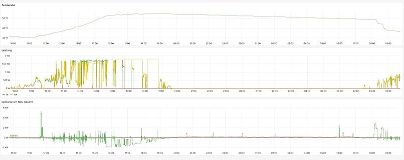
Diagramme von Temperatur, Leistung und Netzleistung über Zeit
:00 20:00 21:00 22:00 23:00 00:00 01:00 02:00 03:00 04:00 05:00 06:00 07:00 08:00 09:00 Leistung 0 W 500 W 1 kW 1,50 kW 2 kW - soll - ist Leistung vom Netz Gesamt 6 kW 4 kW 2 kW 0 W -2 kW
in „Schädigt Phasenanschnittsteuerung einen Heizstab?“ · Haus & Smart Home · · Screenshots
-
PDF
L4971.pdf
Quiescent current vs. junction voltage. temperature Iq D97IN724 D97IN731 (mA) Iq (mA) 200KHz R1=22K 200KHz C2=1.2nF 5 R =22K 5 1 C2=1.2nF 100KHz R 120K 4 C =2.7nF 4 100KHz 2 R1=20K C2=2.7nF 3 3 0Hz 0Hz V =35V CC 2 2 0% DC Tamb=25˚C 0% DC 1 1 0 5 10 15 20 25 30 35 40 45 50 Vcc(V) -50 -30 -10 10 30 50
in „L4791 Step-down stirbt - wieso?“ · Analoge Elektronik und Schaltungstechnik ·
-
PDF
Stern_Dreieck_230V.pdf
AK immer g paarweise l beschalten e X1 X2 X3 X4 X5 X6 Stufe 2 1 & 2, 3 & 4 i 21 21 5 & 6, 7 & 8 r k V K3 K2 Stufe 1 c U1 V2 r i T M 22 22 X1 t r V1 W2 S D A1 A1 A1 A1 A1 A1 W1 3~ U2 K1 K2 K3 X2 K10 K11 K12 A2 A2 A2 A2 A2 A2 N T1 = Entstörung K1, K2, K3 = DIL-EM01 Motor Störung rot Klemmen K10, K11, K12 = Finder 55.34.8.230 L / L X1, X2 (U1, V1) L / L / PE X3, X4 (W1, V2) L / L X5, X6 (W2, U2) L / L X7, X8 (TK)
-
PDF
drv8811.pdf
Dissipation Ratings DERATING BOARD PACKAGE Rθ JA FACTOR TA< 25°C TA= 70°C TA= 85°C ABOVE T =A25°C (1) Low-K PWP 67.5 °C/W 14.8 mW/°C 1.85 W 1.18 W 0.96 W Low-K (2) PWP 39.5 °C/W 25.3 mW/°C 3.16 W 2.02 W 1.64 W High-K(3) PWP 33.5 °C/W 29.8 mW/°C 3.73 W 2.38 W 1.94 W (4) High-K PWP 28 °C/W 35.7 mW/°C 4.46 W 2.85 W 2.32 W (1) The JEDEC Low-K board used to derive this data was a 76 mm x 114 mm, 2-layer, 1.6 mm thick PCB with no backside copper. (2) The JEDEC Low-K board used to derive this data was a 76 mm
in „UV-Laserdrucker II“ · Platinen ·
-
PDF
FN8222.pdf
Techniques Noninverting Amplifier R +5V 1 +V +V LM308A +V VS + +5V VO – VW OP-07 VREF + X -5V VOUT VW/R W – R 2 -5V +V R1 V = V /R V /R OUT W W W W (a) (b) V O (1+R 2R1)VS Voltage Regulator Offset Voltage Adjustment Comparator with Hysteresis LT311A R1 R2 V – S VIN 317 VO(REG) VS VO + R 100kΩ 1 – VO + } } I adj TL072 R1 R2 R2 10kΩ VUL= {R1/(1 + 2 )}OV (max) 10kΩ 10kΩ V = {R /(R + R )} V (min) LL 1 1 2 O VO(REG) = 1.25V (1+2 /1 )adj 2 +12V -12V (for additional circuits see AN115) 9 FN8222.1 September 19, 2005 X9C102, X9C103
in „digitales Poti gesucht“ · Mikrocontroller und Digitale Elektronik ·
