-
PDF
Aeternum_Sheet.pdf
1 2 3 4 5 6 I2C 3.3V - Bus A SCL/1.3A SCL/3.6B A SDA/1.3A SDA/3.6B +3V3 7 6 5 3 D1 3 IC2 SC16IS750 U$2IC$1 PCF8574P BAT43 D2 + R8 13 4 BAT43 T L A /INT P0 GPIO_0 I S D 4 VDD RESET 1 1k +3V3 P1 5 GPIO_1 8
in „CP/M auf ATmega88“ · Mikrocontroller und Digitale Elektronik ·
-
 Bild
Bild
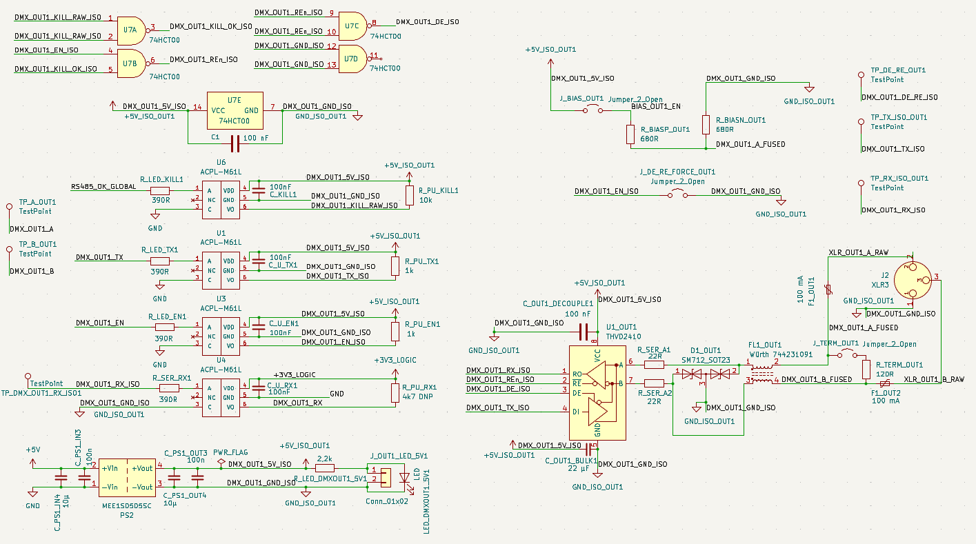
Elektronischer Schaltplan
, R_PU_EN1, 1n, R_PU_RX1, 47, R_SER_RX1, 390R, R_SER_A1, 22R, R_SER_A2, 22R, U1, THVD2410, WÜRTH 744231091, F1_OUT1, 120R, F1_OUT2, 100mA, XLR_OUT_B, XLR_OUT_A, J2, XLR3, J1, XLR, J3, TERM_OUT1_B_FUSED, DMUX_OUT1_GND_JSO, DMUX_OUT1_5V_JSO, DMUX_OUT1_GND_JSO, DMUX_OUT1_RX_ISO, DMUX_OUT1_TX_ISO, DMUX_OUT1_EN_JSO, DMUX_OUT1_KILL_JSO, DMUX_OUT1_GND_JSO
in „Artnet-DMX-Node mit 2× DMX Out + 1× DMX In, komplett galvanisch getrennt - gibt es ähnliche Projekte“ · Mikrocontroller und Digitale Elektronik · · Schaltpläne
-
Datei
ntp.c
\n"); struct NTP_GET_Header *ntp; ntp = (struct NTP_GET_Header *)ð_buffer[UDP_DATA_START]; ntp->rx_timestamp = HTONL(ntp->rx_timestamp); ntp->rx_timestamp += GMT_TIME_CORRECTION; // UTC +1h time = ntp->rx_timestamp; uint16_t tage = (unsigned long)(time/86400); // Tage seit 1.1.1900 tage -= 39445;
in „Webmodule von Ulrich Radig, Problem mit ntp.c“ · Mikrocontroller und Digitale Elektronik ·
-
Datei
ntp.c
) { return; } for (byte_count = 0; byte_count<sizeof( NTP_Request ); byte_count++) { unsigned char b; b = pgm_read_byte(ntp_data_pointer++); eth_buffer[UDP_DATA_START + byte_count] = b; } create_new_udp_packet(byte_count,NTP_CLIENT_PORT,NTP_SERVER_PORT,tmp_ip); NTP_DEBUG("** NTP Request gesendet! **
in „Wie bekomme ich den aktuellen Tag/Stunde aus der Struct indie main.c“ · Mikrocontroller und Digitale Elektronik ·
-
PDF
JRXEWKbQXBFOb1fH.pdf
66x, 6Bx, 6Dx, 71x, 72x, 75x, 76x, 78x, 7Ax, 7Cx, 81x, 82x, 85x, 86x, 88x, 8Ax, 8Cx, 8Dx, 93x, 9Cx, B2x, B5x, BDx, C1x, C3x, C4x, C7x, C8x, CAx v 2373-1Ex, 1Fx, 1Hx, 1Lx, 2Ex, 2Fx, 2Qx, 3Fx, 3Hx, 3Px, 4Fx, 4Gx, 4Hx, 4Nx, 4Px, 4Qx, 4Sx, 5Hx, 5Qx, 5Rx, 6Kx, 6Sx, 7Ex, 7Fx, 7Jx, 7Kx, 7Mx, 7Px, 8Hx, 8Jx,
in „Lenovo T42 Ladeelektronik spielt verrückt“ · Mikrocontroller und Digitale Elektronik ·
-
Datei
main.c
status) #pragma config T3CMX = PORTC0 // Timer3 Clock input mux bit (T3CKI is on RC0) #pragma config P2BMX = PORTD2 // ECCP2 B output mux bit (P2B is on RD2) #pragma config MCLRE = EXTMCLR // MCLR Pin Enable bit (MCLR pin enabled, RE3 input pin disabled) // CONFIG4L #pragma config STVREN = ON // Stack
in „Bezahlte Hilfe: Bluetooth Ein/Aus-Schalter“ · Mikrocontroller und Digitale Elektronik ·
-
PDF
uploaded_files_documents_org13xx_series_datasheet_u2841.pdf
1PPS_GPS 33R (Option) 9 3 8 C1 18pF VIO_1V8 VIO_EXT VCC 21 1PPS 19 1PPS 15 ECLK TSYNC 7 GPIO1 18 GPIO2 R2 (Option) GPIO2 GPIO2_GPS nRESET 16 33R (Option) nRESET RESET U1 20 C2 ON_OFF 17 COMM_SEL ON_OFF ON_OFF 5 18pF (Option) SE 4 SCK 6 R3 TX_D 2 SDO 22 TX_GPS RX_D 1 TX SDI 33R RX C3 GND1 GND2 GND3 GND4
in „Inbetriebnahme ORG-1315“ · Mikrocontroller und Digitale Elektronik ·
-
PDF
arm.pdf
4 6 8 9 8 6 6 74 8 4 0 GND 10n B1 CR1632FH GND 1 6 7 8 1 1 1 1 1 1 2 8 1 3 2 2 2 1 3 4 1 2 4 3 8 ) ) ) ) ) ) ) ) ) ) ) ) ) 134 TRST 3 3 3 3 3 3 3 3 3 3 3 3 3 A E D P2.8 / TD2 / TXD2 / TRACEPKT3 GND 6 5 4 TDI ( 3(3(3 ( 3(3(3 ( 3( ( (
in „LPC2468 External Memory Controller Frage“ · Mikrocontroller und Digitale Elektronik ·
-
Datei
RFM_01_test_868MHz.bas
Call Rf_cmd(&Hc811) 'Datarate: 19,2 kbit Call Rf_cmd(&Hc69b) 'AFC Call Rf_cmd(&Hc42a) 'data filter Call Rf_cmd(&Hc2e0) 'low batt./ clock divider Call Rf_cmd(&Hc042) 'receiver setting: Call Rf_cmd(&He000) 'wake-up timer: Call Rf_cmd(&Hcc00
-
Datei
RFM_01_test_868MHz.bas
Call Rf_cmd(&Hc811) 'Datarate: 19,2 kbit Call Rf_cmd(&Hc69b) 'AFC Call Rf_cmd(&Hc42a) 'data filter Call Rf_cmd(&Hc2e0) 'low batt./ clock divider Call Rf_cmd(&Hc042) 'receiver setting: Call Rf_cmd(&He000) 'wake-up timer: Call Rf_cmd(&Hcc00
-
Datei
testrx.bas
Call Rf_cmd(&Hc811) 'Datarate: 19,2 kbit Call Rf_cmd(&Hc69b) 'AFC Call Rf_cmd(&Hc42a) 'data filter Call Rf_cmd(&Hc2e0) 'low batt./ clock divider Call Rf_cmd(&Hc042) 'receiver setting: Call Rf_cmd(&He000) 'wake-up timer: Call Rf_cmd(&Hcc00
-
Datei
ch552_keil.h
// T2/CAP1 alternate pin enable: 0=T2/CAP1 on P1.1, 1=T2/CAP1 on P1.4 sfr XBUS_AUX = 0xA2; // xBUS auxiliary setting #define bUART0_TX 0x80 // ReadOnly: indicate UART0 transmittal status #define bUART0_RX
in „uC für 0,20€ CH552 / CH554 von WCH Billig Micro mit USB Funktion, Chip vorstellung“ · Mikrocontroller und Digitale Elektronik ·
-
Datei
ch552_keil.h
// T2/CAP1 alternate pin enable: 0=T2/CAP1 on P1.1, 1=T2/CAP1 on P1.4 sfr XBUS_AUX = 0xA2; // xBUS auxiliary setting #define bUART0_TX 0x80 // ReadOnly: indicate UART0 transmittal status #define bUART0_RX
in „uC für 0,20€ CH552 / CH554 von WCH Billig Micro mit USB Funktion, Chip vorstellung“ · Mikrocontroller und Digitale Elektronik ·
-
Datei
init.c
= USART_Mode_Rx | USART_Mode_Tx; USART_Init(USART1, &USART_InitStructure); USART_ITConfig(USART1, USART_IT_RXNE, ENABLE); USART_Cmd(USART1, ENABLE); } void USART2_Configuration(void) { USART_InitTypeDef USART_InitStructure
in „STM32 ADC Fehler“ · Mikrocontroller und Digitale Elektronik ·
-
Datei
enc28j60.c
packet); // Kopiert das Paket aus dem Receive Buffer in den uC buffer // an implementation of Errata B1 Section #13 /* rs = enc28j60Read(ERXSTH); // rs bekommt den wert aus ERXST RX Buffer Start rs <<= 8; // rs |= enc28j60Read(ERXSTL); // re = enc28j60Read(ERXNDH); // re bekommt den wert aus ERXND RX
in „Atmega1280 Webserver stürzt ab“ · Mikrocontroller und Digitale Elektronik ·
-
PDF
MC51F7424_V1.2.2.pdf
to P1.0 RX0_MAP = 0x11; //RX0 map to P1.1 2、 启动 UART0 输出多对一映射: 多路输出映射到同一端口,仅 1 路有效,优先级如下: 功能 优先级 TX0 0 最高级 RX0 1 SCK_OUT 2 MISO_SO 3 MOSI_MO 4 CMP0O 5 CMP1O 6 PWM1A 7 PWM1AN 8 PWM1B 9 PWM1BN 10 PWM1C 11 PWM1CN
in „Lidl kann auch anders (Lötstation)“ · Mechanik, Gehäuse, Werkzeug ·
-
Datei
rfm12_rx.c
; /* * ++++++---- NC in (?) * ||||||+--- UART Tx out * |||||||+-- UART Rx in */ DDRD = 0b00000010; /* * ++------ NC in (?) * ||+----- LED3 out * |||+---- LED2 out * ||||+--- LED1 out * |||||+-- LED0 out */ DDRC = 0b00001111; /* * Initialize UART: 19200 Bd, 8N1, Tx enabled
in „Problem AM-Empfänger konstruieren“ · HF, Funk und Felder ·
-
Datei
Beispiel_Programm.txt
Dx = PortD Bit X ON (X = 2..7)"); uartPutString("\n dx = PortD Bit X OFF (X = 2..7)"); uartPutString("\n iX = config Port(C,B,D) IN mit PullUP"); uartPutString("\n ix = config Port(c,b,d) IN ohne PullUP"); uartPutString("\n gx
in „Programm läuft in schleife?“ · Mikrocontroller und Digitale Elektronik ·
-
Datei
main.c
GPIO_Pin_6; GPIO_InitStruct.GPIO_OType = GPIO_OType_OD; GPIO_Init( GPIOA, &GPIO_InitStruct ); SPI_I2S_DeInit(SPI1); // SPI configuration SPI_InitStructure.SPI_Direction = SPI_Direction_2Lines_FullDuplex; SPI_InitStructure.SPI_Mode = SPI_Mode_Master; SPI_InitStructure.SPI_DataSize = SPI_DataSize_16b;
in „STM32 SPI Mosi Pegel zu niedrig“ · Mikrocontroller und Digitale Elektronik ·
-
PDF
CD4528BM.PDF
Level Output CurrenVDD e 5V, O e 0.4V 0.64 0.51 0.88 0.36 mA (Note 3) VDD e 10V, O e 0.5V 1.6 1.3 2.25 0.9 mA VDD e 15V, O e 1.5V 4.2 3.4 8.8 2.4 mA IOH High Level Output CurrenDDVe 5V, O e 4.6V b 0.25 b0.2 b 0.36 b 0.14 mA (Note 3) V e 10V, V e 9.5V b 0.62 b0.5 b0.9 b 0.35 mA DD O VDD e 15V, O e 13.5V
in „HiLo All-07 IcTest erstellen?“ · Mikrocontroller und Digitale Elektronik ·
-
Datei
msp_code.txt
) { // wait for timer or ADC interrupts } return 0; } /* Timer B0 interrupt service routine */ #pragma vector=TIMERB0_VECTOR __interrupt void Timer_B (void) { } #pragma vector=ADC_VECTOR __interrupt void ADC12ISR (void) { } #pragma vector=UART0RX_VECTOR __interrupt
in „MSP430 UART Timing“ · Mikrocontroller und Digitale Elektronik ·
-
PDF
stm32f030f4-956260.pdf
_RTS (2) (1) (1) PA1 EVENTOUT (1)(3) - - USART4_RX TIM15_CH1N - USART2_RTS USART1_TX (2) (1)(3) PA2 TIM15_CH1 (1)(3) - - - - - USART2_TX o I USART1_RX (2) 0 (1)(3) 4 PA3 TIM15_CH2 (1)(3) - - - - - 8 USART2_RX
in „STM32F030 interne REF ausreichend für 12Bit?“ · Mikrocontroller und Digitale Elektronik ·
-
PDF
en.DM00088500.pdf
_RTS (2) (1) (1) PA1 EVENTOUT (1)(3) - - USART4_RX TIM15_CH1N - USART2_RTS USART1_TX (2) (1)(3) PA2 TIM15_CH1 (1)(3) - - - - - USART2_TX o I USART1_RX (2) 0 (1)(3) 4 PA3 TIM15_CH2 (1)(3) - - - - - 8 USART2_RX
in „Controller IC für digitale RGBW LED-Streifen“ · Mikrocontroller und Digitale Elektronik ·
-
PDF
Multifuse_Sicherung_MF-R.pdf
00 Specifications are subject to change without notice. 11 Tape and Reel Specifications MF-R and MF-RX Series Tape and Reel Specifications Devices taped using EIA468–B/IEC286-2 standards. See table below and Figures 1 and 2 for details. Dimensions IEC EIA Dimension Description Mark Mark Dimensions Tolerance
in „Polyfuse - Auslösezeit im Datenblatt?“ · Mikrocontroller und Digitale Elektronik ·
-
Datei
STM32F10x_Startup.s
TIM2_IRQHandler .word TIM3_IRQHandler .word TIM4_IRQHandler .word I2C1_EV_IRQHandler .word I2C1_ER_IRQHandler .word I2C2_EV_IRQHandler .word I2C2_ER_IRQHandler .word SPI1_IRQHandler .word SPI2_IRQHandler
in „STM32 Memorymanagement Exception“ · Mikrocontroller und Digitale Elektronik ·
-
Datei
testrx.bas
hwstack = 32 $swstack = 10 $framesize = 40 $crystal = 12000000 $baud = 38400 Baud = 38400 Config Pind.2 = Input Nirq Alias Pind.2 Config Pind.7 = Input Portd.7 = 1 'Fsk Alias Portd.7 'Set Fsk Led Alias Portd.5 Config Portd.5 = Output 'LED zur Schleifenkontrolle Dim Count As Byte Dim Temp As Byte Dim Rx
-
Datei
testrx.bas
hwstack = 32 $swstack = 10 $framesize = 40 $crystal = 12000000 $baud = 38400 Baud = 38400 Config Pind.2 = Input Nirq Alias Pind.2 Config Pind.7 = Input Portd.7 = 1 'Fsk Alias Portd.7 'Set Fsk Led Alias Portd.5 Config Portd.5 = Output 'LED zur Schleifenkontrolle Dim Count As Byte Dim Temp As Byte Dim Rx
-
Datei
spi.c
); SPI_CalculateCRC(SPI1, DISABLE); SPI_Cmd(SPI1, ENABLE); } int spi1_tx(int tx) { int tmp=0; SPI_I2S_SendData(SPI1,tx); while(SPI_I2S_GetFlagStatus(SPI1,SPI_I2S_FLAG_TXE)==RESET); tmp=SPI_I2S_ReceiveData(SPI1); return tmp; } int spi1_rx() { int rx=0; while(SPI_I2S_GetFlagStatus(SPI1,SPI_I2S_FLAG_TXE)==RESET); SPI_I2S_SendData(SPI1,0xFF); while(SPI_I2S_GetFlagStatus(SPI1,SPI_I2S_FLAG_RXNE)==RESET); rx=SPI_I2S_ReceiveData(SPI1); return rx; }
in „SPI mit STM32“ · Mikrocontroller und Digitale Elektronik ·
-
PDF
GM47_Integrators_Manual_R1C.pdf
-2.5dB PGA gain 2 0dB PGA gain 3 2.5dB PGA gain 131 LZT 123 7263 R1C GM47/GM48 INTEGRATOR’S MANUAL <TxPGA>, Description <RxPGA> 4 5dB PGA gain 5 7.5dB PGA gain 6 –7.5dB PGA gain 7 –10dB PGA gain <SideToneGain> Description 0 10dB 1 13dB 2 16dB 3 19dB 4 22dB 5 25dB <AuxInputGain> Description 0 MUTE 1 13dB 2 34dB 3 46dB <MicInputGain> Description 0 MUTE 1 13dB 2 25dB 3 34dB 4 46dB <TxAGCGain> Description 0 0dB 1 3dB 2 6dB 132 LZT
in „GM47 GSM Spannungsversorgung aus LiIo-Akku“ · Mikrocontroller und Digitale Elektronik ·
-
Datei
main.c
delay_ms(1); PORTD &=~ (1<<CLK); _delay_ms(1); } } void parser(void) { int direction; char *tmp; char *tmp2; char left_s[20]; char right_s[20]; char steps_s[20]; char *left; // Für: d:l bzw. d:r char *right; // Für n! n=Anzahl der Schritte z.B. 100! char *steps; // Für n if(rx_flag == 1) // Alle Daten empfangen
in „Nochmals Frage zu UART“ · Mikrocontroller und Digitale Elektronik ·
-
Datei
Common.h
; void Hex_Viewer(unsigned char Count); void Error_Counter(void); void Errors(void); void Read_Reg_RX0(void); void Read_Reg_RX1(void); void Rx_Data(void); void Ask_Reset(void); void Hex_Dez(unsigned int Put); unsigned long Retard(unsigned long retard); void Wait_Bottom(void); void Can_Modes(void); int
in „LCD Display am PIC - verstädnisfrage BUS Übertragung“ · Mikrocontroller und Digitale Elektronik ·
-
Datei
boot_tftp_VIP1710_non_signed.txt
: USB hub found hub.c: 2 ports detected insmod: /lib/modules/2.4.30: No such file or directory Using /lib/modules/12ehci-hcd.o ehci_hcd 00:11.2: PCI device 1033:00e0 ehci_hcd 00:11.2: irq 35, pci mem b0002000 usb.c: new USB
in „Pollin MOTOROLA VIP1710“ · Mikrocontroller und Digitale Elektronik ·
-
PDF
GSM_Tracker.pdf
AT-Befehl kompatibel 2 Atmega32 1 Diode 1 PNP-Transistor (BC 560B) 1 Widerstand (250 Ohm) 1 Soll das Mobiltelefon automatisch eingeschaltet werden, sind u.U. weitere Teile notwendig Optokoppler 1-2 Widerstand (250 Ohm) 2 Im
-
Datei
Tiny841-1.c
uart_init(void) { UCSR0B = 1<<RXCIE0 // RX interrupt enabled | 0<<UDRIE0 // TX interrupt disabled | 1<<RXEN0 // RX enabled | 1<<TXEN0 // TX enabled | 0<<UCSZ02 // 8 bits ; UCSR0C = 0<<UMSEL01|0<<UMSEL00 // async mode | 0<<UPM01
in „I2C Slave -> UART im AVR“ · Mikrocontroller und Digitale Elektronik ·
-
Datei
spidevtest.c
for(i=0; i<524288; i++) { tx[i] = rand() % 49 + 1; } uint8_t rx[614400] = {0, }; struct spi_ioc_transfer tr = { .tx_buf = (unsigned long)tx, .rx_buf = (unsigned long)rx, .len = sizeof(tx), .delay_usecs = delay, .speed_hz = speed, .bits_per_word = bits, }; ret = ioctl
in „Daten Übertragung über SPI (bufsiz, takt, multichannel??)“ · Mikrocontroller und Digitale Elektronik ·
-
Datei
dmxdim.asm
, tempL sbi DDRB, PB1 cbi PortB, PB1 ;enable reception (RE DE low am 75176bp) sbi DDRD, PD2 cbi PortD, PD2 ; Baudrate einstellen/UART initialisieren ;-------------------------------------------------- ldi tempL, ((F_OSC/4000)-1) ;set
in „DMX Empfangsproblem mit ATMega16 und Hennes lib @ ASM“ · Mikrocontroller und Digitale Elektronik ·
-
PDF
WT11_Data_Sheet.pdf
WT11 D a t a S h e e t V e r s i o n 2 . 6 F r i d a y , N o v e m b e r 1 6 , 2 0 0 7 Copyright © 2000-2007 Bluegiga Technologies All rights reserved. Bluegiga Technologies assumes no responsibility for any errors, which may appear in this
in „WT11 von Bluegiga, Registrierung?“ · Mikrocontroller und Digitale Elektronik ·
-
PDF
Schaltplan.pdf
1 2 3 4 5 6 7 8 A A U1 ESP32-WROOM-32D(16MB) B GND 39 GND B GND 1 38 2 GND GND 37 GND VCC VDD33 IO23 WS2812 Ch3 EnableEN IO22 36 SCL 12V Input SENSOR_VP TXD0 35 TX 12V Input Rot 34 6 SENSOR_VN RXD0 33 RX
in „LD1117 3.3 V wird warm“ · Analoge Elektronik und Schaltungstechnik ·
-
Datei
MYSENSORS_GatewayClient_WORK_V3.ino
[] = { /* {presentation, set/req, description} */ {0,0,"free"}, {0,0,"free"}, {0,0,"free"}, //D2 : Std-fkt; '15' = IR_Rx?? '6' =ImpCount; '31' =tft; <<user IO-Shield20<< {0,0,"free"}, //D3 : Std-fkt; '7' = 433_Rx?? '6' =ImpCount; '31' =tft; <<user IO-Shield20<< {0,0,"free"}, //D4 : Std-fkt; '7'
in „String Array verarbeiten / Arduino“ · Mikrocontroller und Digitale Elektronik ·
-
Datei
main.c
Korrekturfaktor genau 9606bps UCTL0 &= ~SWRST; // USART freigeben IE1|= URXIE0 + UTXIE0; // TX- und RX-interrupts anschalten IFG1 &= ~UTXIFG0; // Initales interrupt-flag loeschen } void init_uart_1(void) { WDTCTL = WDTPW + WDTHOLD; // Watchdog aus P3SEL |= 0xC0; // P3.6 und 3.7 als USART1 TXD/RXD ME2
in „MSP430 GPS-Daten von UART0 Probleme“ · Mikrocontroller und Digitale Elektronik ·
-
Datei
txtext.asm
: cpi RX, 12 ;Clear all brne com12 ldi YL, low(DDRAM) ldi YH, high(DDRAM) ldi temp, 32 ldi temp2, high(XSize*YSize+DDRAM) clrloop2: st Y+, temp cpi YL, low(XSize*YSize+DDRAM) cpc YH, temp2 brne clrloop2 ldi YL
in „AVR Videogenerator, 40x25 Zeichen, nur 60% CPU Auslastung !“ · Projekte & Code ·
-
PDF
Webserver1.pdf
JP2_22 D6 JP1_16 A6 D6 JP2_21 A7 JP1_15 A7 D7 D7 A8 A8 A9 JP1_14 A9 COL_LED JP2_6 COL_LED A10 JP1_11 A10 TX_LED JP2_8 TX_LED A11 JP1_12 A11_MISO RX_LED JP2_10 RX_LED A12 JP1_9 A12_MOSI LINK_LED JP2_12 LI_LED
in „WIZ810 (WIZ5100) an XMEM Interface (AVR)“ · Mikrocontroller und Digitale Elektronik ·
-
Datei
grab32.py
), 'RLA_Ventil': ('b', 2,3), 'Pumpe_Boiler': ('b',2,5), 'Pumpe_Puffer': ('b',2,7), 'Keine_Stoerung': ('b',3,0), 'Zuendung': ('b', 3,2), 'Drehrost': ('b',3,6), 'Reinigung': ('b',3,7), 'Raumaustragung_Saugturbine': ('b',4,1
-
PDF
SARA-G3_DataSheet__UBX-13000993_.pdf
) SARA-G350-01B GSM Connected Mode All 850, 1 Tx + 1 Rx slot (voice or data call 200 250 mA (Call enabled) 900 up to 21.4 kb/s UL, 21.4 kb/s DL) Maximum Tx power (32.2 dBm typ.) 1800, 1 Tx + 1 Rx slot (voice or data
in „GSM-Modul (SIM908) nur analoge Ausgänge für Anruf?“ · HF, Funk und Felder ·
-
Datei
code.txt
3 (USART RX) */ NVIC_InitStructure.NVIC_IRQChannel = DMA1_Channel3_IRQn; NVIC_InitStructure.NVIC_IRQChannelPreemptionPriority = 2; NVIC_InitStructure.NVIC_IRQChannelSubPriority = 0; NVIC_InitStructure.NVIC_IRQChannelCmd
in „USART Remapping“ · Mikrocontroller und Digitale Elektronik ·
-
Datei
code.txt
3 (USART RX) */ NVIC_InitStructure.NVIC_IRQChannel = DMA1_Channel3_IRQn; NVIC_InitStructure.NVIC_IRQChannelPreemptionPriority = 2; NVIC_InitStructure.NVIC_IRQChannelSubPriority = 0; NVIC_InitStructure.NVIC_IRQChannelCmd
in „USART Remapping“ · Mikrocontroller und Digitale Elektronik ·
-
Datei
main.c
esp_system.h" #include "driver/gpio.h" #include "driver/uart.h" #define UART_NUM UART_NUM_1 #define UART_RX_GPIO GPIO_NUM_4 #define LIN_BAUDRATE 9600 static const char *TAG = "LIN_SNIFFER"; // Setup UART buffered IO with event queue const int uart_buffer_size = (1024 * 2); QueueHandle_t uart_queue; void uart_event_task
in „TJA1020 mit ESP32 betreiben“ · Mikrocontroller und Digitale Elektronik ·
-
Datei
Bootlog_VIP1710_mit_Soft.TXT
: USB hub found hub.c: 2 ports detected insmod: /lib/modules/2.4.30: No such file or directory Using /lib/modules/12ehci-hcd.o ehci_hcd 00:11.2: PCI device 1033:00e0 ehci_hcd 00:11.2: irq 35, pci mem b0002000 usb.c: new USB
in „Pollin MOTOROLA VIP1710“ · Mikrocontroller und Digitale Elektronik ·
-
Datei
main.c
-------- // SPI support functions void chip_select(int RAM_bank) { switch (RAM_bank) { case 0: // 0b000 GPIOA->BRR |= (GPIO_Pin_2 | GPIO_Pin_1 | GPIO_Pin_0); break; case 1: // 0b001 GPIOA->BRR |= (GPIO_Pin_2 | GPIO_Pin_1); GPIOA->BSRR |= (GPIO_Pin_0); break; case 2: // 0b010 GPIOA->BRR |= (GPIO_Pin_2 | GPIO_Pin_0); GPIOA->BSRR |= (GPIO_Pin_1); break; case 3: // 0b011 GPIOA->BRR |= (GPIO_Pin_2); GPIOA->BSRR |= (GPIO_Pin_1 | GPIO_Pin_0); break; case 4: // 0b100 GPIOA->BRR |= (GPIO_Pin_1 | GPIO_Pin_
in „OV7670 an STM32F102“ · Mikrocontroller und Digitale Elektronik ·
-
Datei
dds-pll.asm
mode (3), positive pwm ldi tmp,128 out ocr0b,tmp ldi tmp, (1<<com0b1) + 0* (1<<com0b0) + (1<< wgm00) + (1<< wgm01) out tccr0a,tmp ldi tmp,1 ; max clock out tccr0B,tmp ; set Table for sinewave output ldi r31,high(2*sine) ; setup Z pointer hi ldi
in „PLL mit Atmega8 läuft + Fragen!“ · Mikrocontroller und Digitale Elektronik ·