-
PDF
Ansteuerung.pdf
- G 1 8 8 C23 C24 C25 1 ENA D 33R T4 5 C T D6 E E T D8 1 9 9 50V 35V 25V 8 ENB G 1 T3 K 6 8 8 5 R 10 10 100n 470u 1u TP17 D 3 5 1 1 7 2 11 11 3 C 8 4 J J 4 12 D X S S X 12 S Z T6 T7 Z C B 1 2 3 4 1 2 3 4 B n h GND S 2 5 5 , D9 , D11 R37 2 2 - - 1 8 8 X X B B TP21 GND 56k 20k 1M JU1 R2 R3 R4 GND Jumper
in „IRF1405PBF Mosfet wird zu heiss und verabschiedet sich“ · Analoge Elektronik und Schaltungstechnik ·
-
PDF
AOA_Application_Board_revA.pdf
LPC11C24 C77 GND 2 C78 GND 4 RESET/PIO0_0 3 PIO0_0-RESET GND GND GND 18P 18P PIO0_1/CLKOUT/CT32B0_MAT2 10 PIO0_1 6 PIO0_2/SSEL0/CT16B0_CAP0 14 PIO0_3 GND GND GND 7 XTALIN PIO0_3 15 PIO0_4-I2C_SCL CN_+3V3 XTALOUT PIO0_4/SCL 16 PIO0_5-I2C_SDA R119 R120 3 PIO0_6/SCK0 23 PIO0_6 LM75 I2C Temperature Sensor 60R
in „Probleme mit LPC11C24“ · Mikrocontroller und Digitale Elektronik ·
-
PDF
Microchip_AppNote_00994a.pdf
cause high crest factor signals, such as those in Figure 2 (and also overcurrent situations), the 10(40) A, Class 1. This would be an I Nf 10A and an design goal is to keep the VRMS signal of channel 0 to IMAX of 40A. around half of the full-scale input range at I . Not MAX Power factor also plays a
in „Strom 10A bis 300A messen mit Tiny26“ · Mikrocontroller und Digitale Elektronik ·
-
PDF
surrpressordiode.pdf
10 35.5 16.9 (+SMBJ9.0A KV AV 10.0 11.1 1.0 9.0 10 39.0 15.4 (+) (+)MBJ10 KW AW 11.1 13.6 1.0 10 5.0 31.9 18.8 SMBJ10A KX AX 11.1 12.3 1.0 10 5.0 35.3 17.0 (+SMBJ11 KY KY 12.2 14.9 1.0 11 5.0 29.9 20.1
in „DC Geräteeingang“ · Analoge Elektronik und Schaltungstechnik ·
-
Datei
evalboard.c
// Pin 6 von Port D als Eingang nutzen PORTD |= 0x40; // pull-up Widerstand aktivieren DDRD &= ~0x10; // Pin 4 von Port D als Eingang nutzen PORTD |= 0x10; // pull-up Widerstand aktivieren if ( (PING & 0x01) == 0) { // Zustand auslesen DDRD |= 0x80; // Pin 7 von Port D als Ausgang nutzen PORTD |= 0x80
in „Evalboard AVR Mega128 Board“ · Mikrocontroller und Digitale Elektronik ·
-
PDF
ICL7660.pdf
L N N V 0 I 50 50 E T S R U -1 E 40 40 U T V C U -2 N 30 30 L O C P -3 R 20 20 U E TA= 25°C S -4 W 10 + 10 SLOPE 55Ω P V = +5V -5 0 0 0 10 20 30 40 50 60 70 80 0 10 20 30 40 50 60 LOAD CURRENT I (mA) LOAD CURRENT I LmA) L FIGURE 7. OUTPUT VOLTAGE AS A FUNCTION OF OUTPUT FIGURE 8. SUPPLY CURRENT AND POWER
in „+5V zu -5V wie?“ · Mikrocontroller und Digitale Elektronik ·
-
PDF
7660CPA.pdf
L N N V 0 I 50 50 E T S R U -1 E 40 40 U T V C U -2 N 30 30 L O C P -3 R 20 20 U E TA= 25°C S -4 W 10 + 10 SLOPE 55Ω P V = +5V -5 0 0 0 10 20 30 40 50 60 70 80 0 10 20 30 40 50 60 LOAD CURRENT I (mA) LOAD CURRENT I LmA) L FIGURE 7. OUTPUT VOLTAGE AS A FUNCTION OF OUTPUT FIGURE 8. SUPPLY CURRENT AND POWER
in „OPV mit +4,5/-4,5V von einer 9V Batterie betreiben“ · Analoge Elektronik und Schaltungstechnik ·
-
PDF
ICL7660.pdf
L N N V 0 I 50 50 E T S R U -1 E 40 40 U T V C U -2 N 30 30 L O C P -3 R 20 20 U E TA= 25°C S -4 W 10 + 10 SLOPE 55Ω P V = +5V -5 0 0 0 10 20 30 40 50 60 70 80 0 10 20 30 40 50 60 LOAD CURRENT I (mA) LOAD CURRENT I LmA) L FIGURE 7. OUTPUT VOLTAGE AS A FUNCTION OF OUTPUT FIGURE 8. SUPPLY CURRENT AND POWER
in „Spannungsabfall durch drei Tl074 :-S“ · Analoge Elektronik und Schaltungstechnik ·
-
PDF
MCS8051_Evoboard.pdf
7 VCC P3.6 7 VCC 7 P0.7 8 P1.7 8 P2.7 8 P3.7 8 8 B 9 9 9 9 9 B 10 10 10 10 10 Port P0 Port P1 Port P2 Port P3 Port P4 +UB IC2 VCC VCC +UB 3V3 VCC BU1 A1 7805 IC3 R33 1 4 AC V+ 1 1 Vin Vout 3 3 IN OUT 2 2 D D5 1 ADJ 0R (* see text in manual) 3 AC V- 2 G C3 CON2 C15 C16 C17 C18 grün LM1117-3V3 10µF/16V DF005 10µF/16V 100nF 100nF 10µF/16V Title A 2 R6 Microcontroller,RS232,TWI(I²C),USB,Power,Reset, A 470R PortsundLED's Size Number Revision EVOB0004 REV_A A4 Date: 29-Oct-2005 Sheet of
in „Gesucht: Mikrocontroller mit LAN und CAN“ · Mikrocontroller und Digitale Elektronik ·
-
Datei
rotary.txt
******************************************************************* ; Der Wertebereich des ADC ist 10 Bit: ; 0 = 0x0000 = 0 V ; 1023 = 0x03FF = +2.5 V ; ************** 89C51CC03 ************************ ;Vorgesehene Peripherie: ;CAN-Schnittstelle (MCP2551SN): ; P4.0 TxDC ; P4.1 RxDC ;RS232: ; P3.0 RxD
in „8051 Projekt Rotary Encoder“ · Mikrocontroller und Digitale Elektronik ·
-
PDF
FliegendesAuto.pdf
auf, durch wie viele Studium der Marktlage einen Absatz von Ausrüstungsteile die Verkehrssichetheit 10 000 l\{aschinen.Da er sich iedoch aus einesStraßenfahrzeuges erkämpft werden Gtünden der Wirtschaftlichheit aufeinen muß ! Scheinwerfer,Parklicht, Stopplicht, Automotor versteitteblieb esbei einenr rX
-
PDF
FPGA_Kits_Vergleich_120205.pdf
SPI (ST M25P16) - - Flash - 16MB parallel - 16MB StartaFlash Intel 16MB StartaFlash Intel - Ethernet 10/100 PHY DP83848J 10/100 PHY LAN8710 10/100/1000 PHY 10/100 PHY - - Marvell M88E1111 SMSC LAN83C185 RS232 - - - Two 9-pin (DTE and DCE) Two 9-pin (DTE and DCE) - USB-A plug Micro-AB High speed Micro-AB
in „Vergleich und Erfahrung zu LX9 MicroBoard, Nexys 3 und Atlys“ · FPGA, VHDL & Co. ·
-
PDF
C500-System.pdf
ert der R ege l i rih tung dar c hen :V erfugb arse iein R eferen zelem en tm it stell. A l H eize lm ent nu tzt m an d en pn p e i em T em p eraturko efgz in ten von T K ure Tra nsist r V 2, d essen m ontag efreun dlih es = 10 0· 10-6 K -1, der m i H ilfe ein es T her Flach geh äuse T O 126 fur d ie hier v orgese ' o staten auf T K ure = 10 ·10 -6K - 1 verm in hen e A nw end ung b eson ders geeign etist.D er d ert w erden soll. D as erreich t m an jedoc h Tra nsistor V 2 sow ie d ie B au el m ente N 1 n ur m it einem T herm o staten, dessen
in „IC C500 Schaltplan“ · Analoge Elektronik und Schaltungstechnik ·
-
PDF
Elektor83.PDF
10po LS78.. 1,50 1S368. 1,10 4055 3,05 6520PtO......10,50 lcl8038.....13,20 LS85, 1,75 1S373. 2,75 4060 1,80 65204PIO tcM7224.....39.50 LS86, -,90 1S374. 2,75 4066 -,90 2MHVtA......16.95 s1480........6,
in „Das Ende des Z80“ · Mikrocontroller und Digitale Elektronik ·
-
PDF
A_Design_of_High_Speed_and_Real-time_DSO_Based_on_FPGA.pdf
: i2J1ii111;iir.LEt11taitEl;!I{8,t~l&;Ii;n, -e:teiJ1:8',fi'f"'5:R --Nil:fjj~lEii.iiliJ1tMiliMU-rJ<:lm~fi, [i8',*!I+!® $ ,Jr.Ji5X1,Ht''j!jj.\''~;I, "'1'l&ffie1l:EJ;~llliii:ffi. jJIj:i~jlf1!ell8, 1110, 9d'1/4t%jlf'ii~mtJl>T 10Jil. Et;1taiiE1:E;Iit:J!:(,!iiH!, 1t1<eiJj*+ <I'fi"I'fiJ ,8:<:~tifif..H'tM4ii1
in „Oszilloskop - SoC“ · Analoge Elektronik und Schaltungstechnik ·
-
PDF
Schematic.pdf
100nF C2 AD5 16 5 2 RX- RD- RD- i Lan CP_LA 1 LA AD6 17 6 i 2 AD7 18 7 Lan 11 6 R_Tx+1 22pF RY1 CP_RST 10 RESET TD+ TD+ i Lan 10M Y1 21 VCC i TX+ C3 8 C4 20 MHz 28 ALE CP_ALE 10 7 GND 1 27 XTAL1 22 Lan CTX CTD R_Tx-1 GND XTAL2 RD (DS) CP_RD B 9 8 100nF TD- i Lan 22pF 8 23 B TX- TD- 8 3V3 19 VCC WR (R/W)
in „PoE AVR Modul“ · Markt ·
-
PDF
CamperDisplayBattery.pdf
X MOS3 IN BTS410 - D 0 2 3 VDD T _ 1 4 A N MOS3STATUS STATUS U16 B GND P16 5 VOUT I C G +5V 3 E U8 LM7805CT Q8 1 8 C6 R SHDN NC V T1-252-4:TO-263-23ead 1 IRML9301TRPbF 2 GND LT3009ADJ/NC 7 +3.3V C14 C22 C30 C53 IN D OUT C33 C35 C38 2 3 6 1uF G 10K GND U2 OUT RR23 4 GND IN 5 100nF 4,7uF 10uF 100uF 2 1uF
in „Akku und Wasserstandsdisplay für Wohnmobile“ · Projekte & Code ·
-
PDF
TX-H2560SW21C-2770V36-03H95_WKF-DB0002.pdf
machinery must be properly grounded. Part No. TX-H2560SW21C-2770V36-03H95 Spec No. WKF-DB0002 Page 3 of 10 www.txled.cn Version:2.0 Electrical Optical Characteristics (Tc=25°C) Parameter Symbol Condition Emitting Min. Typ. Max. Units color S — 4450 — Luminous Flux φv lm W — 6300 — S 33 35 37 Forward Voltage
in „Implementierung einer CCT LED mit ELG-100-36-3Y Netzteil und PWM-Dimmung über Arduino“ · Mikrocontroller und Digitale Elektronik ·
-
PDF
HEIZUNG_UNGARN.PDF
30 2 GSM P IU10 11 PD2 (INT0) PC2 (TCK) PIU102 1 LCD2 D2 P IJ 10 3 GSM 1 P IU10 12 PD3 (INT1) PC3 (TMS) PIU102 2 33R P0 P IJ 10 4 C ISP GSM 2 P IU10 13 PIU102 3 LCD3 C GSM 3 P IU10 14 PD4 (OC1B) PC4 (TDO) PIU102 4 LCD4
-
Datei
NRF24_SendRcvMIesp.ino
Sending Limit:")); DEBUG_OUT.println(Limit); UsrData[0]=0x5A;UsrData[1]=0x5A;UsrData[2]=100;//0x0a;// 10% limit UsrData[3]=((Limit*10) >> 8) & 0xFF; UsrData[4]= (Limit*10) & 0xFF; //WR needs 1 dec= zB 100.1 W size = hmPackets.GetCmdPacket((uint8_t *)&sendBuf, dest >> 8, DTU_RADIO_ID >> 8, Cmd, UsrData,5
in „Wechselrichter Hoymiles HM-xxxx 2,4 GhZ Nordic Protokoll?“ · Mikrocontroller und Digitale Elektronik ·
-
Datei
main.c
#include "stdio.h" #include "math.h" /* * linux: gcc main.c -o main -lm http://williams.best.vwh.net/avform.htm#Dist Some great circle formulae: Distance between points The great circle distance d between two points with coordinates {lat1,lon1} and {lat2,lon2} is given by
in „GPS distanz berechnung“ · Mikrocontroller und Digitale Elektronik ·
-
PDF
1W_LED_RGB_luxeon_spec.pdf
LED Flux Characteristics (T j= 25°C ;FI = 350m) Wave Length Luminous Color Ordering Code (nm) Flux(lm) 620~630 Red 30~40 520~530 Green 60~70 NPT1RGB306015S-L Blue 460~470 15~25 Note: NPT maintains a tolerance of +/- 4% on flux measurements. Characteristics Characteristics Unit Minimum Typical Maximum ViewingAngle degrees 115 120 125 DC forward current mA 370 DC pulse current (@ 1kHz, 10% duty cycle) mA 500 Reverse voltage V 5 Reverse Leakage current @5V uA 10 Forward Voltage @350mA– Green, Blue V 3.0 3.4 3.6 Forward Voltage @350mA– Red V 2.0 2.4 2.6 LED Junction Temperature °C 120 Suggested
in „Re: [Sammelbestellung] 6 Pin 3W Power RGB LED“ · Markt ·
-
Datei
website.c
#include <stdio.h> #include <math.h> // gcc -Wall -Wextra -std=c99 website.c -lm // *********************************************************************************************************** // Daten: float my_data[300]; const size_t len_my_data = sizeof(my_data) / sizeof(my_data
in „Graphik mit einfachem Wlan Webserver ohne Internet“ · Mikrocontroller und Digitale Elektronik ·
-
PDF
noname.pdf
1 2 3 4 5 6 Eig ein 2937ET-3.3 +5V U1 +3.3V LM2931AZ-3.3/5.0 TO92-123 3 VI VO 1 D C G C 2 C4 C5 IC2 DOGM128 7 C C 1 1 NC(A1+) V0(LCDrive) 21 1 A 2 22 C C A +3.3V GND +3.3V NC(A2+) V1(LCDrive) C C 2 IC1 3 NC(A3+) V2(LCDrive) 23 1 LED 24 C C 7 VCC
in „DOGM128L-6 Kontrastspannung“ · Mikrocontroller und Digitale Elektronik ·
-
PDF
Praesi_Technik.pdf
die zu Verschweißenden Bauteile S. 9 Gehäuse Mikrowellentrafo sorgt für den nötigen Schweißstrom S. 10 Gehäuse Arduino MEGA mit Touchdisplay Einstellungen und Programmablauf S. 11 Gehäuse Netzschalter Allpolig S. 12 Gehäuse Anschluss Fußtaster 4mm Buchsen S. 13 Gehäuse Geräte- Sicherung Träge 4A S. 14
in „kleines Punktschweißgerät“ · Mechanik, Gehäuse, Werkzeug ·
-
PDF
Copter00.pdf
Eagle-Daten\projects\Quadcopter\Copter00.sch (Sheet: 4/5) GND GND GND GND GND GND C27 C28 9 k 3 k 2 8 10n 10n 4 8 1 R 6 R 6 0 1 k k 2 R 1 1 R 1 3 k47 3 1 S6 1 D S12 0 0 C3 R27 1 G N 0 9 1 k 2 1 S C G 2 k 1 R 1S6 - Mode2 R N 2 S5 - Mode1 1 R G 1 2 8 2 1 S4 GND D C 4 S11 0 3 MOD1 N N 1 0 6 R 1 3 4 R R12 C2 N Q G R 4 3 1 R RF-MODUL-2.4G 7 1 2 10n I N R 2 1 S3 3 O C I E N Q S X S10 R5 GND 3 M S M C G I C R R15 3 4 GND GND 4 3 S1 S2 1 2 3 4 5 6 7 8 9 2 2 S9 S8 R R 3 1 3 1 GND 1 3 1 3 4 2 4 2 2 4 2 4 1k0 1k0 1k0 1k0 R9 R8 R17 R18 5 YAW-THROTTLE
in „Hackbarer(?) 21 EUR Quadcopter“ · Mikrocontroller und Digitale Elektronik ·
-
PDF
Methode_2.pdf.pdf
ist mit der zuvor in Z Abschn. 6.5.4 ermittelten korrekten PhasenreservePM =17,2. M 100 0 Z/Grad 10 17,2 20 30 40 50 Bild 6.9Interpolationskurve zu Bild 6.8 (Auswertung der Anstiegs-Extremwerte) 6.6.3 Modifikation des Verfahrens Wenn durch den in die Rückkopplungsschleife eingefügten zusätzlichen Block
in „OPV GBW fuer Filter“ · Analoge Elektronik und Schaltungstechnik ·
-
PDF
ICL7660.pdf
O N N V 0 I 50 50 E T S R P -1 E 40 40 U T V C O -2 O 30 30 L C P -3 R 20 o 20 U E TA= 25 C S -4 O 10 V+= +5V 10 SLOPE 55Ω P -5 0 0 0 10 20 30 40 50 60 70 80 0 10 20 30 40 50 60 LOAD CURRENT IL(mA) LOAD CURRENT IL(mA) FIGURE 7. OUTPUT VOLTAGE AS A FUNCTION OF OUTPUT FIGURE 8. SUPPLY CURRENT AND POWER
in „Ladungspumpe“ · Mikrocontroller und Digitale Elektronik ·
-
PDF
5988-7313EN.pdf
Luminous Intensity Forward Voltage. vs. DC Forward Current. 40 m 35 – T 30 N R 25 R C 20 D R A 15 R O 10 F –F 5 I 0 0 20 40 60 80 100 TA– AMBIENT TEMPERATURE – °C Figure 4. Maximum DC Current vs. Ambient Temperature. 7 10° 0° 20° 1.0 30° 10 SEC. MAX. 40° .8 T S 230°C MAX. N E 50° E R .6 N T PRE-HEAT 140
in „Verk. LED HSMF-C655“ · Markt ·
-
PDF
lts_6-np.pdf
response time Typ Max ●● Wide frequency bandwidth TCV OUT Temperature coefficient of V OUT@ I P 0 - 10°C .. + 85°C 80 200 ppm/K ●● No insertion losses - 40°C .. - 10°C 250 ppm/K ●● High immunity to external 3) TCG Temperature coefficient of G - 40°C .. + 85°C 50 ppm/K interference V OM Magnetic offset
-
PDF
SK-schaltplan.pdf
22MF-EA-25V R3 C22 C23 D1 SOC1 SOC10 10 VPP PB0 19 SOC19 SOC5 4 NMI PA3 13 2 4.7K 100nF 100nF R4 VDD-x5 SOC11 11 RESET/ PB1 18 SOC18 SOC10 5 VPP PB0 12 1 GND SOC12 12 PB7 PB2 17 SOC17 SOC11 6 RESET PB1 11 560 'X0/x5 SUPPLIES SOC13 13 PB6
in „ST Chip auslesen“ · Mikrocontroller und Digitale Elektronik ·
-
Datei
setup.c.diff
fb_videomode __initdata grasshopper_tft_modes[] = { { - .name = "LQ043T3DX02 480x272 @ 60", + .name = "Sharp LM64K101", .refresh = 60, // refresh rate - .xres = 480, // horizontal resolution - .yres = 272, // vertical resolution - .pixclock = KHZ2PICOS(9000), // pixel clock in kHz - .left_margin = 2, // h. front porch - .right_margin = 2, // h. back porch - .upper_margin = 10, // v. front porch - .lower_margin = 11, // v. back porch - .hsync_len = 41, // hsync length - .vsync_len = 10, // vsync lengt - .sync = 0, // Active low hsync/vsync + .xres = 640, // horizontal resolution
in „AVR32 Grashopper mit Monochrom-Display?“ · Mikrocontroller und Digitale Elektronik ·
-
PDF
DE2008071001.pdf
V als Referenz an. FETsdauerndleiten,denndasergäbeparti- Heraus kam die abgebildete, gegenüber Alle10 msliegenentwederanAC1oderan elleKurzschluss-Impulse(hörbaramhellen dem ursprünglichen Entwurf quasi hal- AC3 negative Spannungs-Peaks. Wenn die Brummen des Trafos). Ein guter Anfang ist bierte Schaltung
in „Howto Aktiver Gleichrichter“ · Analoge Elektronik und Schaltungstechnik ·
-
PDF
d03000.pdf
10-polig, gerade X50 RS-485 Schnittstelle Wannenstecker 3-polig X60 Analog 1 Wannenstecker, 10-polig, gerade X61 Analog 2 Wannenstecker, 10-polig, gerade X62 PORTB Wannenstecker, 10-polig, gerade X63 PORTC Wannenstecker, 10-polig, gerade X64 PORTD Wannenstecker, 10-polig, gerade X65 PORTE Wannenstecker, 10-polig, gerade X66 PORTJ Wannenstecker, 10-polig, gerade KK1 Kühlkörper Kühlkörper für Spannungsregler KK2 Kühlkörper
in „PIC18F97J60 als Webserver“ · Mikrocontroller und Digitale Elektronik ·
-
 Bild
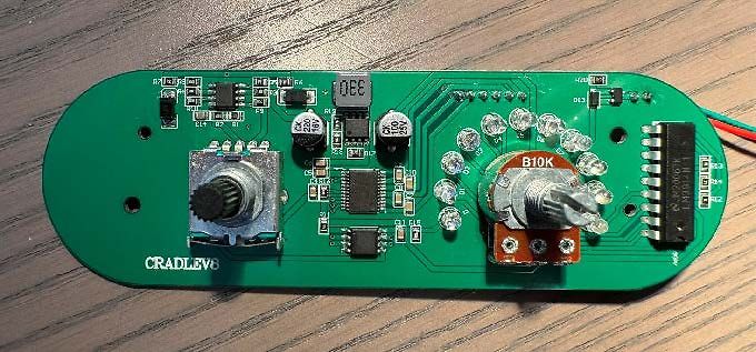
Grüne Leiterplatte mit Potentiometern und elektronischen Bauteilen
CRADLEV8, 220, 100, B10K, LM317
in „Hilfe bei Reparatur von Federwiegen-Motor“ · Analoge Elektronik und Schaltungstechnik · · Platinenfotos
-
 Bild
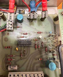
Bestückte Leiterplatte mit LM723CN Spannungsregler
LM723CN, 35V 10 MF, Tracon JAPAN, 27V
in „Anderes Labornetzteil“ · Analoge Elektronik und Schaltungstechnik · · Platinenfotos
-
 Bild
Komplexer elektronischer Schaltplan
ATmega8, LM317, BC547, 10k, 100nF
in „DCF-Uhr from Scratch“ · Mikrocontroller und Digitale Elektronik · · Schaltpläne
-
 Bild
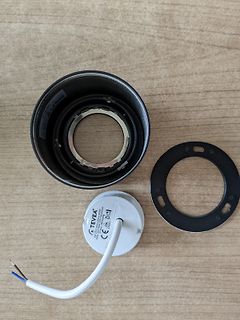
Einzelteile einer Leuchte oder eines Leuchtmittels
TEVEA 230V 50Hz 640lm 4000K 10W CE
in „LED Aufbau-Spot Metallgehäuse Schutzklasse 2“ · Haus & Smart Home · · Fotos
-
 Bild
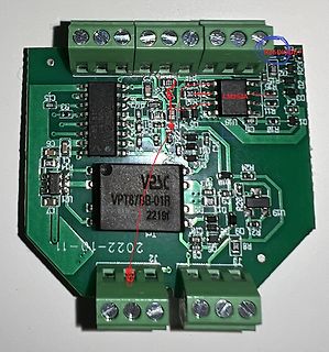
Foto einer Leiterplatte mit LM393A und VPT873B-01B
LM393A VPT873B-01B 2219f 2022-10-11
in „Shelly Addon Analog IN von 0-10V auf 0-5V oder 0-3V umbauen?“ · Analoge Elektronik und Schaltungstechnik · · Platinenfotos
-
PDF
KWH057GM03-F01.pdf
INPUT4+ SPCK 43 SPENA 0.1uF/50V 50K Vmain 4 11 VGLO OPEN SPDA 42 SPCK OPEN VCC GND POL 41 SPDA POL 5 10 L DGND 40 POL 1 INPUT2+ LM3243+ O B07 39 DGND 2 P B7 R101 1 6 INPUT2- INPUT3- 9 B06 38 B6 VGLO R106 VR101 VCOMAC1 1 3 B05 37 B5 0 OPEN R102 7 OUT2 OUT3 8 VR103 B04 36 B4 C314 1 3 D302 ) 2 100K B03 35
in „SAMMELBESTELLUNG: 4" TFT Display mit 24bit digital interface“ · Markt ·
-
 Bild
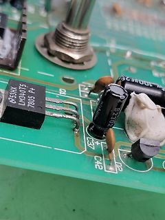
Nahaufnahme einer Leiterplatte mit elektronischen Bauteilen
LM340T 7805 P+ 10 53HX C37+ C42 02 nichicon B2302
in „Auswuchtmaschine Balco B930 defekt, Fehlersuche“ · Analoge Elektronik und Schaltungstechnik · · Platinenfotos
-
 Bild
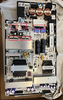
Leiterplatte eines Schaltnetzteils mit roten Markierungen
Ver 1.3, H165, 20CK-LM65, B604232701, 11, 10, 22, 22, 22, 2
in „LG OLED65C97LA lässt sich nicht mehr einschalten“ · Analoge Elektronik und Schaltungstechnik · · Platinenfotos
-
 Bild
PCB-Layout Ausschnitt eines IC-Footprints
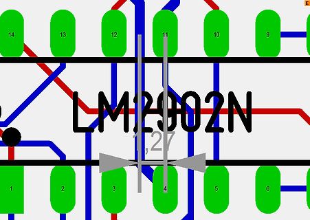
LM2902N 1,27 1 2 3 4 5 6 9 10 11 12 13 14
in „Target Leiterbahn verlegen Darstellung“ · Platinen · · Layouts