nr_inodes=4056183,mode=755,inode64) devpts on /dev/pts type devpts (rw,nosuid,noexec,relatime,gid=5,mode=620,ptmxmode=000) tmpfs on /run type tmpfs (rw,nosuid,nodev,noexec,relatime,size=3263144k,mode=755,inode64) /dev/mapper/vgmint-root on / type ext4 (rw,relatime,errors=remount-ro) securityfs on /sys/kernel
Fiche technique es BHM 09S Micrófono de mano Hoja de datos de BHM 09S Handmikrofon mit Schalter (7 620 230 012 001) zur Anwendung bei Busanlagen. en BHM 09S Hand microphone with switch (7 620 230 012 001) for use with coach systems. fr BHM 09S Microphone à main avec interrupteur (7 620 230 012 001) destiné
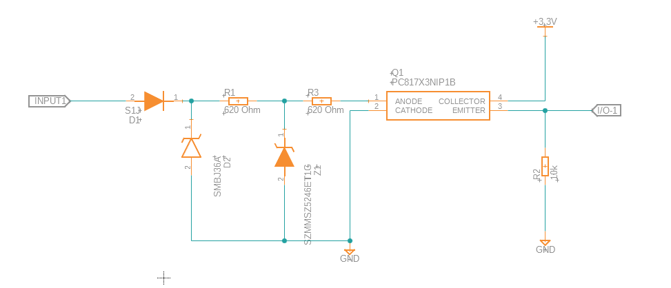
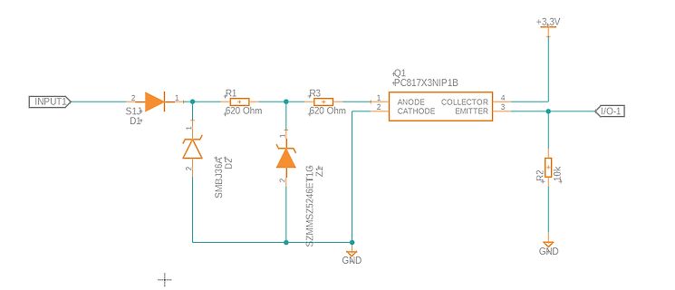
für den Optokoppler hab ich wie folgt berechnet: (U-VF)/IF=R (14,4V-1,2V)/0,01A=1320 Ohm ~ 2x 620 Ohm Max. Spannung 36V: (U-VF)/R=I (36V-1,2V)/1240Ohm=28mA Min. Spannung 8V: (8V-1,2V)/1240Ohm=5,4mA Die Z-Diode (Z1/16V) soll die Spannung begrenzen. Sorry, jetzt beim nochmal
dein Optpkoppler muss nur 330uA schalten, dafur reicht auch dem schlechtesten 1mA. Mach also aus 620 Ohm eher 6k2. Die OpzikoplerLED hält meistens 50mA aus, dann reichen die 13.4k Vorwiderstand bis 670V, du brauchst keine Spannungsbegrenzung per Transil. Su brauchst noch nicht mal eine Vorstabilisierung
44,00x44,00mm bis 0402 ( 1,00x0,50mm) - 5.000 - 7.000 Bauteile pro Stunde - Inline für Leiterplatten bis 620x400mm - Datenaustausch via Diskette möglich (Disketten USB Adapter) - inkl. Windows 10/11 Software zum Offline Programmieren und erstellen der Bestückungsdaten - inkl. 50x 8mm Feeder, 5x 12mm Feeder
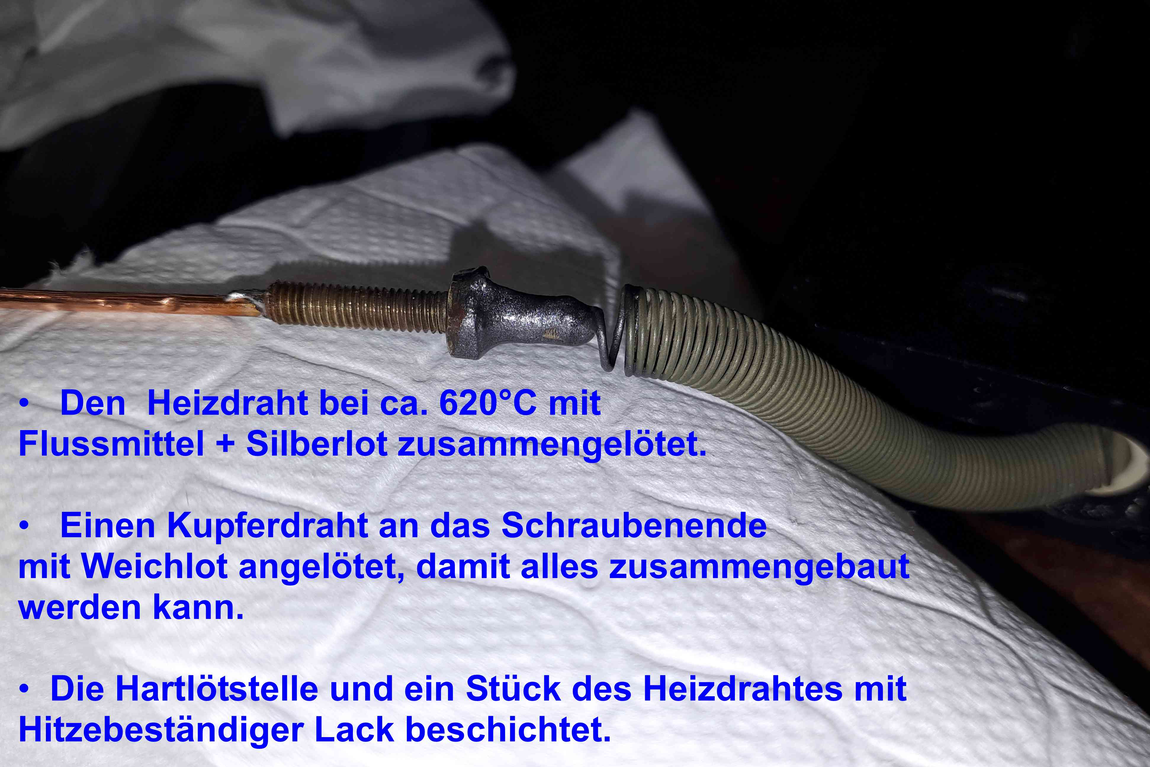
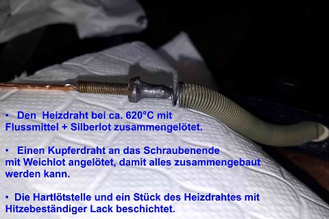
Den Heizdraht bei ca. 620°C mit Flussmittel + Silberlot zusammengelötet.
Einen Kupferdraht an das Schraubenende mit Weichlot angelötet, damit alles zusammengebaut werden kann.
Die Hartlötstelle und ein Stück des Heizdrahtes
ist, die wahrscheinlich 1% bis 2% absoluten Fehler hat, da bist due wenn du nur 0..500mV nutzt mit 620 Schritten genau genug unterwegs, der Lineraitätsfehler ist zwar nicht in der Doku zu finden, wird aber so groß nicht sein das verstärkung etwas bringt. Wenn due mehr Auflösung haben willst, klar,
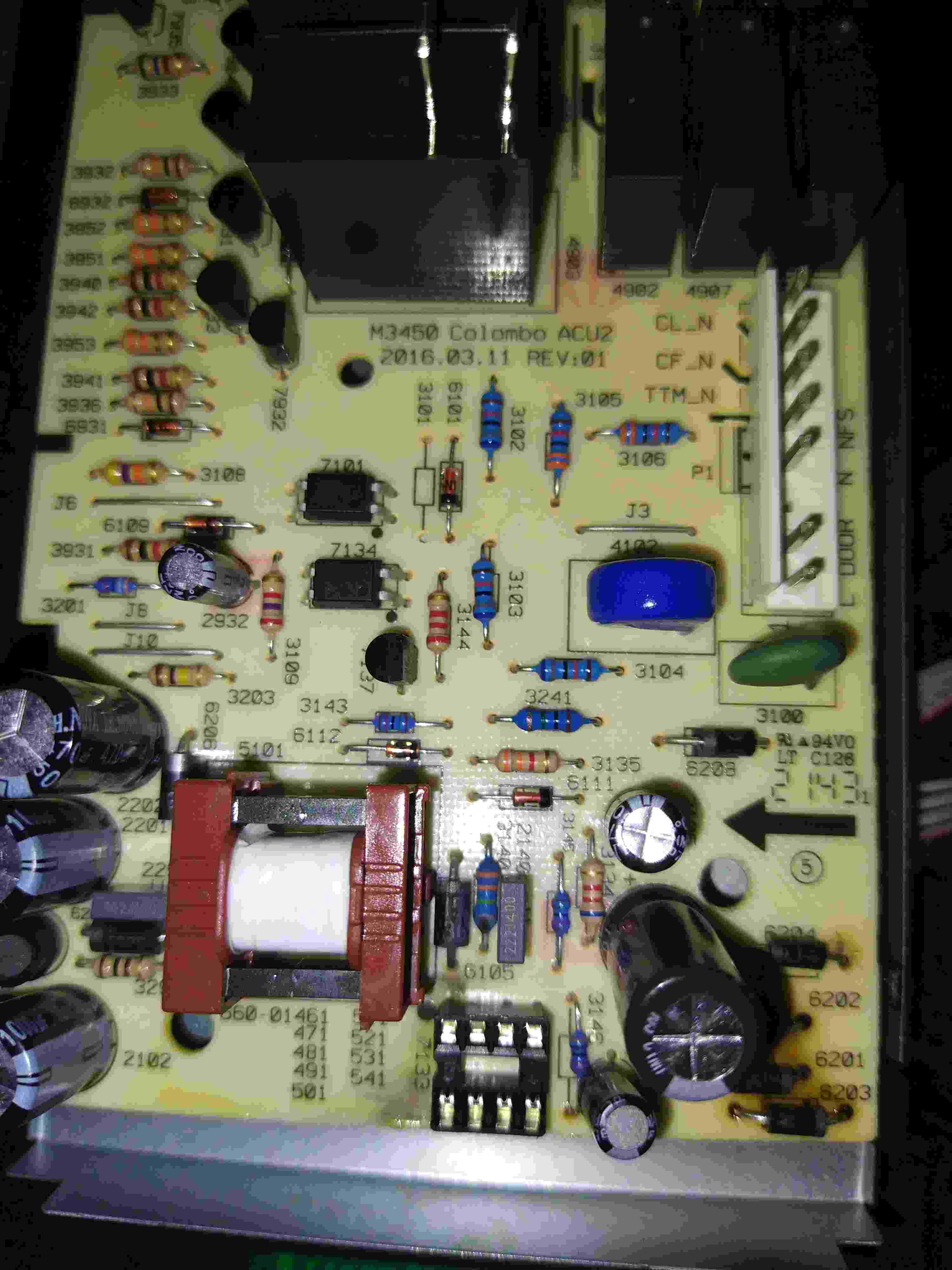
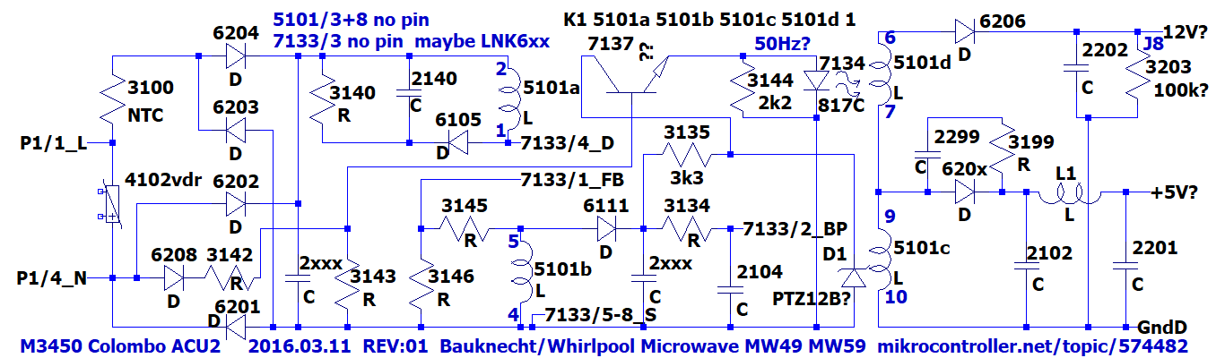
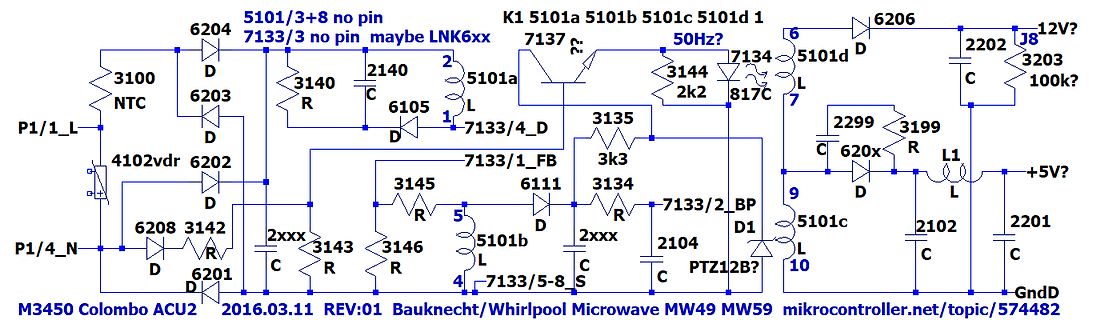
7137 50Hz? 7134 5101d D 2202 J8 3203 100k? 3100 NTC 2140 3140 C 6105 R 5101a 7133/4_D L 2299 3199 C 620x R L1 +5V? 6203 D 6105 1 7133/4_D 3135 7 3144 2k2 817C 9 620x D 3146 R 3143 R 2xxx C 6201 D 6111 3134 R 7133/2 BP 2104 C 2102 2201 C 6208 D 3142 R 5101b 7133/1_FB 5 3145 R 4 7133/5-8 S 5101c 10 PTZ12B
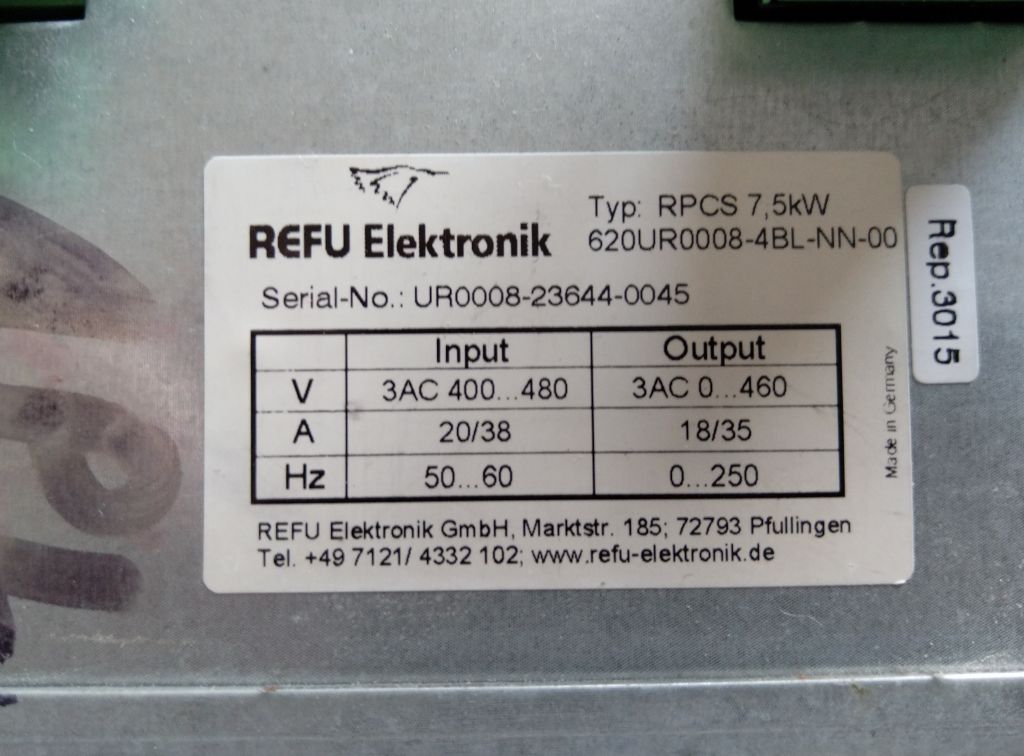
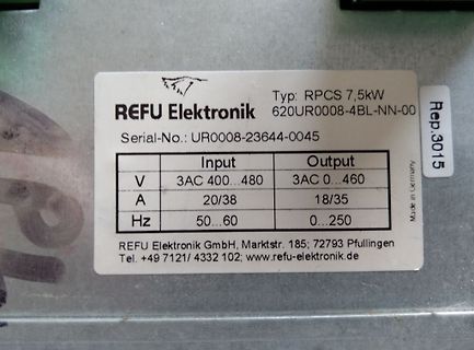
REFU Elektronik
Typ: RPCS 7,5kW
620UR0008-4BL-NN-00
Serial-No.: UR0008-23644-0045
Input V 3AC 400...480
A 20/38
Hz 50...60
Output 3AC 0...460
A 18/35
Hz 0...250
Made in Germany
Rep.3015
REFU Elektronik GmbH, Marktstr. 185; 72793 Pfullingen
15V r 2 R r {cd} = R {csource} = D13 r r hvn R43 R10 R12 C29 Q26 r=1k 3 Q12 4 3 33p } hvp R r R47 r=620 r=620 r d 9 1 2 C10 2 o 15V C27 { 2 t {csource} R r D14 {cd} r R 3 o r=300 R5 3 R18 = Q22 4 3 2 r R r Q1 Q7 out r=1k Q13 R44 r=10k 1 0 r=k00k } } Q27 + V1 1 1 1 1 c C28 { 3 R r R r C11 4 u {cd} r R
PSMN3R3 77Q55-1u25 PSMN2R4 PSMN2R4 -40YS -40YS -30YLD -30YLD C20 4.7µF 35V R4 R5 R6 R7 R8 R9 R10 R11 620K 2.2R 2.2R 620K 620K 2.2R 2.2R 620K n *GND* *GND* *GND* *GND* i GND GND GND GND GND t r a *VCC* e VCC S *3V3* l 3V3 3V3 i 8 7 6 5 n 8 7 6 5 C31 C24 t C25 C34 C33 100nF N t C u 2.2µF o N t C u 2.2µF
side of the 430-ohm to crystal X1 (The pin closest to the edge of the board). 3. Attach one side of a 620-ohm resistor to the junction of the wire and the 430-ohm resistor. The two resistors will “sandwich” the wire going to X1. 4. Attach another 30-AWG wire from the +3.3 V oscillator output (bottom of U7) to the open end of the 620-ohm resistor. Status: Fixed Board Rev: Rev C Figure 9. Voltage Divider Figure 10. Close-up of Voltage Divider 18 DBPXA250 and DBPXA210 Development Platforms Specification Update Downloaded from www.Manualslib.com
271-8511 TWX 910-860-5178 docu-trck. DLS036 36 Amp, 3 Phase Full-Wave Silicon Integrated Rectifiers R620 Controlled Avalanche Series with 250V, 450V, 650V and 850V Minimum Avalanche Ratings R630 Series with 100V,200V, 400 V, 600 V and 800 W^, Ratings (CONTROLLED MAXIMUM RATINGS AVALANCHE) SYMBOL UNITS
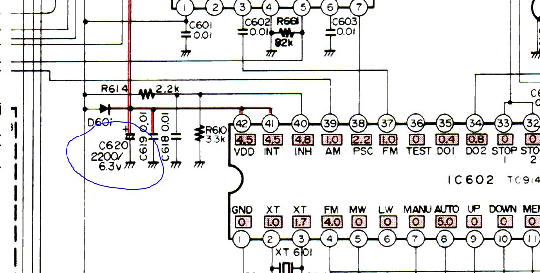
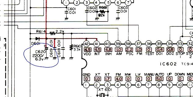
). Welche Kapazität die schadlos aufladen können habe ich nicht untersucht. Die Pufferzeit von C620 reicht nur Minuten oder vielleicht eine Stunde. Bernhard
. Man könnte aber einen „Superkondensator“ zusätzlich parallel zu C620 einbauen und in Reihe zum „Superkondensator“ einen Widerstand einbauen, der dessen Ladestrom begrenzt. C620 wird benötigt, um IC602 ausreichend zu versorgen, bis es über INH auf Stand-by geschaltet
W. schrieb im Beitrag #7783710: > Link/Datenblatt? https://static6.arrow.com/aropdfconversion/620efa92b76ee71c409739b2e728688b68d4208d/sp-rf-ant-prod-db-spa_2400_360_4_20_v_en.pdf Rainer W. schrieb im Beitrag #7783710: > "abzugeben" hört sich nach "Markt" an ... ...und dann gehört auch noch
Hmmm schrieb im Beitrag #7783714: > https://static6.arrow.com/aropdfconversion/620efa92b76ee71c409739b2e728688b68d4208d/sp-rf-ant-prod-db-spa_2400_360_4_20_v_en.pdf Wenn man das Datenblatt liest, kommt man schon etwas ins Schmunzeln. Da geben sie bei den elektrischen Eigenschaften
High voltage response, stable during most of the ▪ Nominal capacity (15k Ohm Cont., 2.0 V cut-off) 620 mAh lifetime of the application ▪ Minimum Open circuit voltage (at + 20 °C) 3.0 V ▪ Reliable Performance ▪ Standard Continuous Discharge Current 0.8 mA ▪ Child-Safe Markings & Retail Packaging ▪ Wide
So geht Energiewende mit staatlicher Förderung! https://www.bild.de/politik/inland/620-mio-euro-steuergeld-so-redet-habeck-sich-bei-northvolt-pleite-raus-674f26c271ebfe079c8fe4f0 *BUAAAAAHHHHHH* Mal sehen wieviele Erfolgsprojekte noch zu verzeichnen sind.
Model CR2450P/H Specifications Nominal Discharge current 0.4mA Nominal Voltage 3V Nominal Capacity 620(mAh) Continuous standard load 7.5(kΩ) Maximum pulse current 28mA Operating temperature -20℃~70℃ Weight 6.9(g) UL Recognition MH29853 Storage temperature range 0℃-30℃ Storage humidity range 35%~75% Characteristics
funktioniert alles gut. Auch die Steuerung durch das PWM Signal. Stromstärke: 700 mA pro Farbe Rot: 620-625nm, 2.0-2.2V Grün: 520-525nm, 3.2-3.4V Blau: 460-470nm, 3.2-3.4V Kaltweiss: 6000-6500K, 3.2-3.4V Hat jemand eine Idee an was das liegen könnte ? Ich zweifel irgendwie an mir selber. Finde den
Temperature DS1820" set xlabel "Minutes (mins)" set ylabel "Temperature (°C)" set terminal png size 620,360 set output "/var/www/html/gnuplot_tempds1820.png" set xdata time set timefmt "%s" set format x "%H:%M" set grid set key left box plot "/home/pi/Temperatur/gnuplot_temp_ds1820.dat" using 1
C W D9314 R9363 3 1 1N4148W 100K 1 % N N + C9357 C9358 R9356 C9350 + N C9352 C C NC/1uF NC/1uF NC/620ohm 1/8W +/-1% C NC/100N 50V N 0 R 0 R NC/470uF 25V 1 C R C9354 R 3 R 3 C9356 0 9 F K 3 NC/2N2 50V 1 5 1 5 NC/470uF 25V K 3 C9353 1 5 % 3 % 4 R9366 O 4 NC/1N 50V 8 1 R9357 0R05 M PS_ON W NC/3K3 1/8W

 Bild
Bild
 Bild
Bild
 Bild
Bild
 Bild
Bild
 Bild
Bild
 Bild
Bild
 Bild
Bild
 Bild
Bild
 Bild
Bild
 Bild
Bild
 Bild
Bild
 Bild
Bild
 Bild
Bild
 Bild
Bild
 Bild
Bild
 Bild
Bild
 Bild
Bild