-
 Bild
Bild
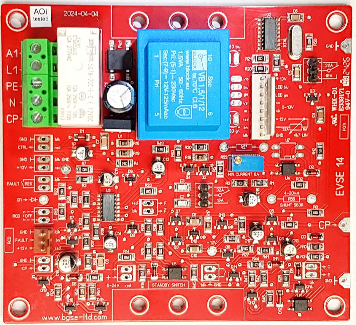
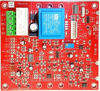
Rote Leiterplatte einer EVSE Steuerung
AQI tested 2024-04-04 A1 L1 PE N CP GND CTRL +13V FAULT RES RCD GND +13V CP GND U2 C8 TAX R51 GND R21 R20 R22 R23 R24 R25 R26 R27 R28 R29 R30 R31 R32 R33 R34 R35 R36 R37 R38 R39 R40 R41 R42 R43 R44 R45 R46 R47 R48 R49 R50 R51
-
Thread
Gibt es einen Ringkern mit der Bezeichnung G2-3/FT16?
.50 MHz. Aber die Schaltung ist tricky, weil die einen DG-Mosfet einsetzen. Daher das Gefrickel mit L1, L2, L3, R5 und R6. Für eine Breitband-Loop findest du im Internet wesentlich bessere Schaltungen oder auch was fertiges: https://active-antenna.eu/amplifier-kit/
Link fehlt). Hier nochmal rauskopiert was darin bezüglich der besagten Ferritkern Induktivität (L2) steht. In der Teileliste ist die bezeichnet als "G2-3/FT16" (4mH6, 40 Windungen CuL. 0,3mm, 0,23R): "Zunächst montiert man die Drahtbrücken (inklusive JP1 und JP2), dann ist L2 an der Reihe.
-
 Bild
Bild
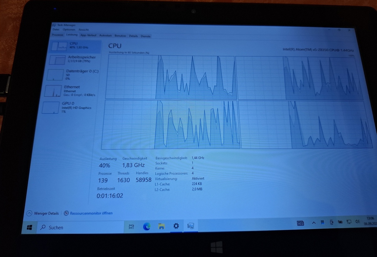
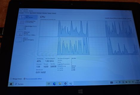
Foto eines Computerbildschirms mit Task-Manager
Task-Manager CPU 45% 1,83 GHz Intel(R) Atom(TM) x5-Z8350 CPU@ 1.44GHz Arbeitsspeicher 3,1/3 GB (79%) Datenträger 0 (C:) 30% Ethernet Ethernet Ges.: 0 Empf.: 0 KBit/s GPU 0 Intel(R) HD Graphics 1% Auslastung 40% Geschwindigkeit 1,83 GHz Basisgeschwindigkeit: 1,44 GHz Sockets: 1 Kerne: 4 Logische Prozessoren: 4 Prozesse 139 Threads 1630 Handles 58958 Virtualisierung: Aktiviert Betriebszeit 0:01:16:02 L1-Cache: 224 KB L2-Cache: 2,0 MB
-
Thread
Schrittmotor und Treiber für Drehkondensator
habe Schwierigkeiten mich da zurecht zu finden. Ebenso bei den Treiber-ICs. Da gibt es einfache (L297/L298) und intelligente (A4988, DRV8825), alles auch jeweils schon fertig auf einem Board. Das Ganze soll in einem wasserdichten Gehäuse im Außenbereich eingesetzt und ferngesteuert werden. Die
Peter L. schrieb im Beitrag #7929985: > kann man da nicht eine Kapazitätsdiode einsetzen? Da mit dieser Antenne nicht gesendet wird wäre das wohl grundsätzlich möglich. Allerdings wäre es sicher nicht sinnvoll
-
Thread
[V] Whip Antennen 5 Stück im Pack
2352380670613&abcId=10011854&merchantid=5077326283&gad_source=1&gad_campaignid=21664105386&gclid=Cj0KCQjw_L_FBhDmARIsAItqgt5RXdi3adul3RuhdVEgAUMuZFrjeL1m-Rz8uL4UX-oacJcZEFQj1oEaArjEEALw_wcB
0GUv0ZLumT9x5AvjXhx1YK2Qsw9BEW_ExJNh9CLJoBp5jcPLH4D4BqTDTUI05PQVYj1hFIvrxeQX9qsNwh7vDnx9z0feX9dSf9QCNSiZoLQ7rfwu4l7nrYR1cUGsWnBVaTLG7kZXJ9N5co0TYs8H8EyvzvWsu_0kKScpzxx79id3b-byok7M.kYW6u5ode2suvb0vW0F1HElE0NyyEFO8RFDK4Ik9E5M&dib_tag=se&keywords=whip+antenne&qid=1756374072&sprefix=whip+antenne%2Caps%2C212&sr=8-5
-
 Bild
Bild
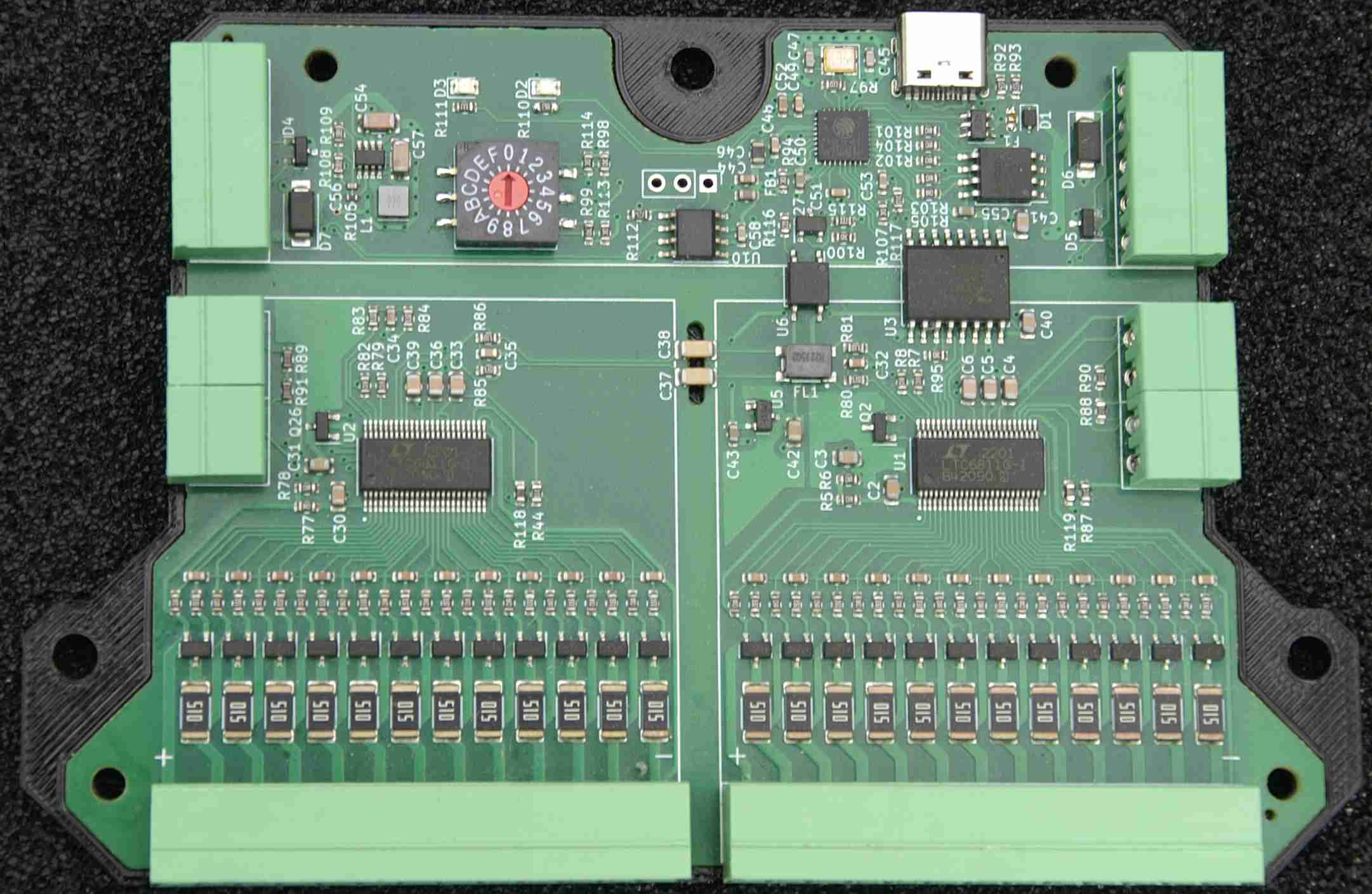
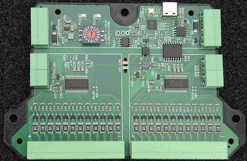
Grüne Leiterplatte mit integrierten Mikrocontrollern und Steckverbindern
R111, D3, R104, R109, R108, R106, R105, L1, D7, R103, C54, C57, R111, D3, R102, R114, R113, R98, C48, C49, C46, C47, R101, R102, R104, R107, R108, R109, R110, R112, R113, R114, R99, R98, R97, R96, R95, R94, R93, R92, R91, R90, R89, R88, R87, R86, R85, R84, R83, R82, R81, R80, R79, R78, R77, C31, C30, C35, C34, C33, C32, C31, C30, C29, C28, C27, C26, C25, C24, C23, C22, C21, C20, C19, C18, C17, C16, C15, C14, C13, C12, C11, C10, C9, C8, C7, C6, C5, C4, C3, C2, C1, U1, U2, U3,
-
Artikel
KiCad
ATMEGA644. Von obi Media:Symbols_ICs-Diskrete_RevD10.lib KiCad Symbole für einige diskrete ICs. Enthält L200 (Pentawatt Gehäuse), LM2587 (Pentawatt Gehäuse), Längstregler LM317, LM78xx, LM79xx, Timer NE555, NF-Verstärker LM1875 und TDA2003 (Pentawatt Gehäuse), Schaltregler UC38xx (DIP8/SO8 und DIP14/SO14
von International Rectifier für KiCad. Enthält die SH, SJ, SQ, ST, S1, MN, MP, MT, MX, MZ und die L8-Outline. Nähere Informationen in den Datenblättern betroffener Transistoren und in der International Rectifier Applikationsnotiz AN-1035. "directFET" ist übrigens eine Handelsmarke von International
-
Thread
Tracker für Rasenrobi
Preise um gute 10,-€ jetzt wohl ändern. Ali bietet zumindest mir den aktuell im Bündelangebot für 5,79€ an.
Michael L. schrieb im Beitrag #7936134: > Ralf X. schrieb im Beitrag #7936114: >> Michael L. schrieb: >>> Das Ding ist aber, daß Dir das nix nützt, wenn einer der Rasenroboter >>> mitnimmt. >> >> Du hast
-
Thread
Platinen Anschluss?
wie Serie 1121 2 x 5 polig https://www.nexus-de.com/de/catalog/items/6cb22faa-a5db-4177-aa6c-e78e79a2a1a8/1_27_x_1_27_mm_THT_Stift-_und_Wannenleisten/ und dann in der Basisplatine den Gegenstecker. Wobei ich 2 x 3 polig 2.54mm Pfosten nehmen würde, gerade in Verlangerung der Platine angelötet
unterschied-adressierbarer-leds-wie-ws2812b-sk6812-neopixel-und-mehr?srsltid=AfmBOoqnCFLVBUcq77ig910Fot7lMhYJUEe_cjA1fVGP1k0N7nomAf-4
-
 Bild
Bild
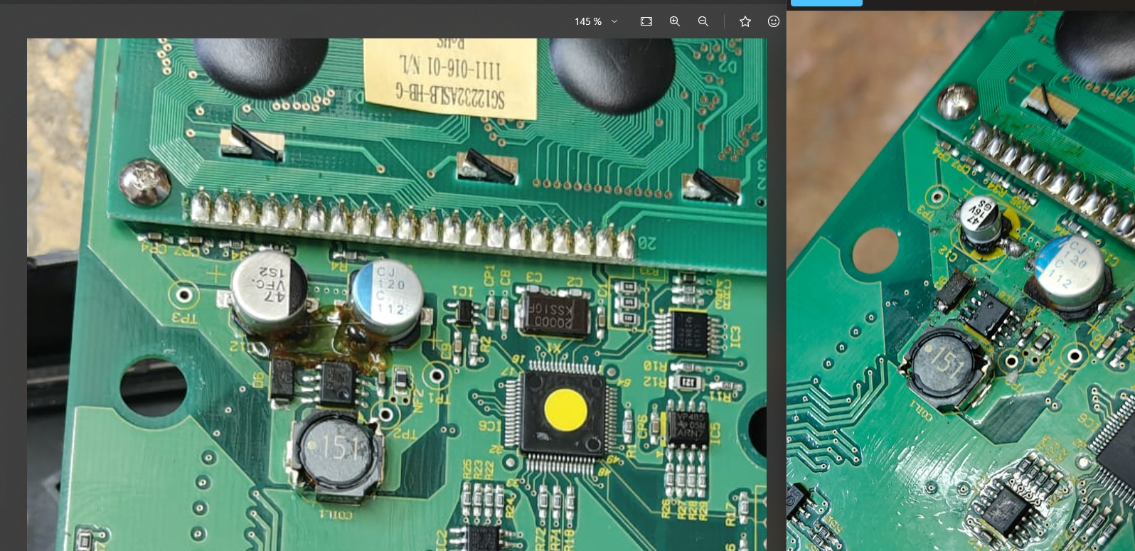
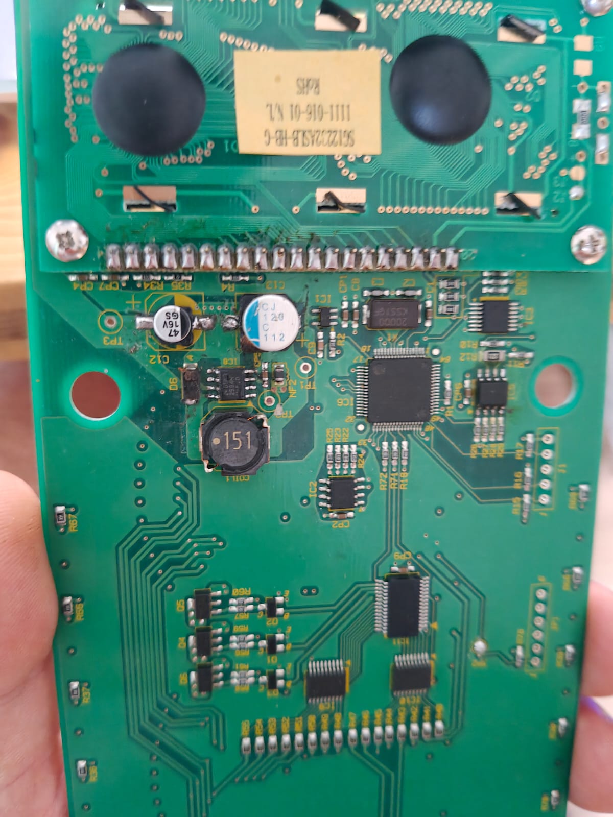
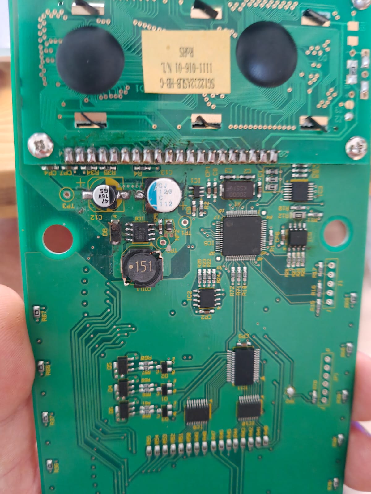
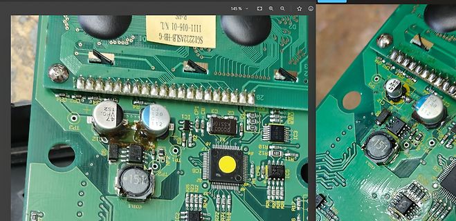
Nahaufnahme einer Leiterplatte mit elektronischen Bauteilen
1111-016-01 N/L, 47, 120 112, IC1, C3, C2, C1, C4, R12, R10, R11, R13, R17, R25, R23, R21, R22, R24, R26, R27, R28, R29, R30, R31, R32, R33, R34, R35, R36, R37, R38, R39, R40, R41, R42, R43, R44, R45, R46, R47, R48,
-
 Bild
Bild
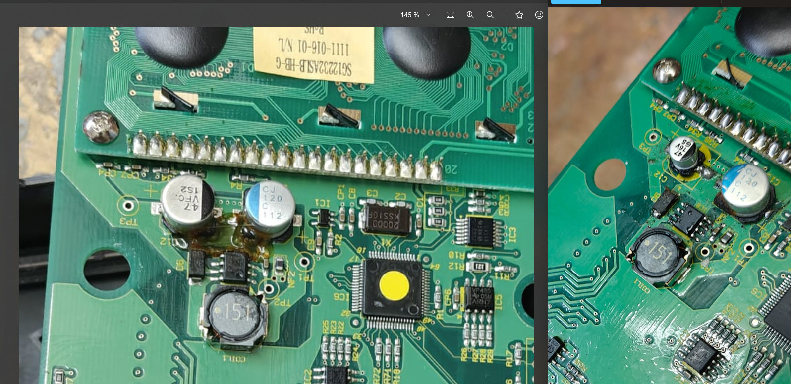
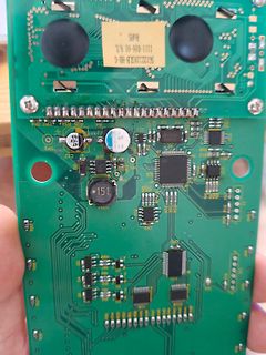
Foto einer grünen Leiterplatte mit elektronischen Bauteilen
1111-016-01 N.L. SG1222ASJB-HB-6 ROHS 47 15V 112 151 C12 C13 C14 C15 C16 C17 C18 C19 C20 C21 C22 C23 C24 C25 C26 C27 C28 C29 C30 C31 C32 C33 C34 C35 C36 C37 C38 C39 C40 C41 C42 C43 C44 C45 C46 C47 C48 C49 C50 C51 C52
-
 Bild
Bild
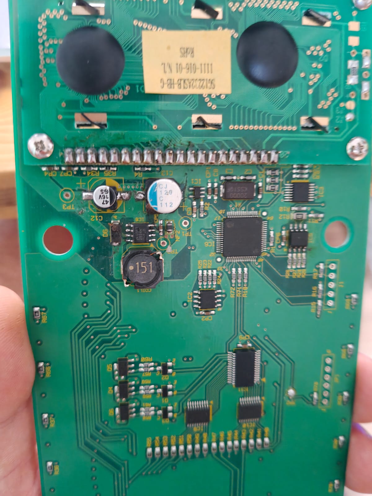
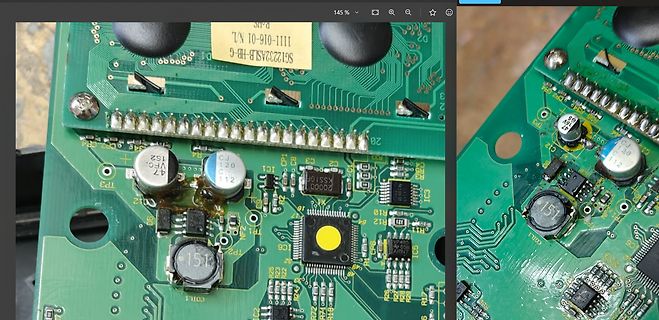
Nahaufnahme einer Leiterplatte mit elektronischen Bauteilen
1111-016-01 N/L, 47, 120 112, IC1, C3, C2, C1, C4, R12, R10, R11, R13, R17, R25, R23, R21, R22, R24, R26, R27, R28, R29, R30, R31, R32, R33, R34, R35, R36, R37, R38, R39, R40, R41, R42, R43, R44, R45, R46, R47, R48,
-
 Bild
Bild
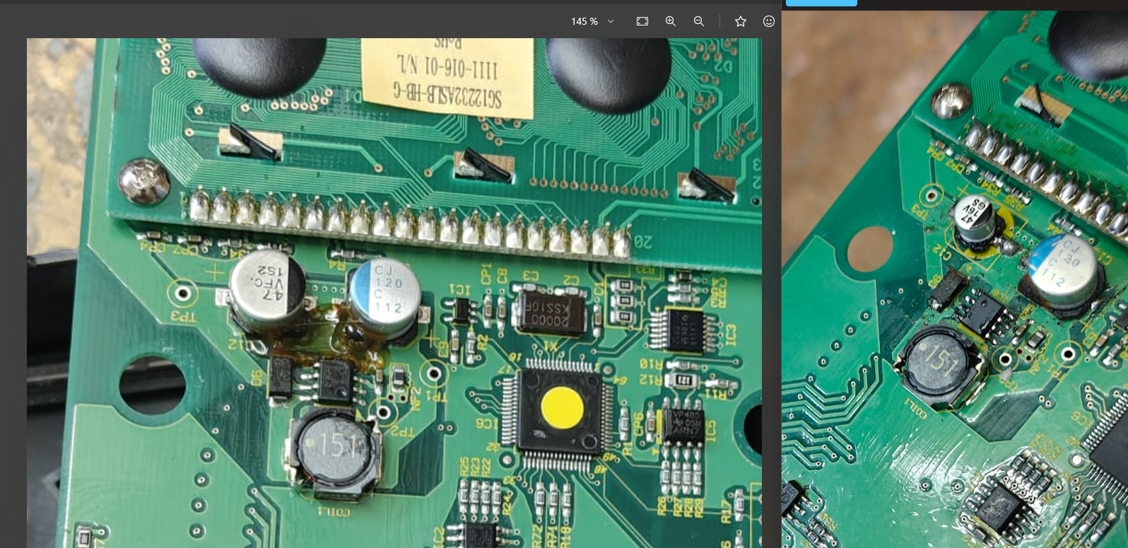
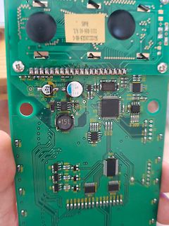
Foto einer grünen Leiterplatte mit elektronischen Bauteilen
1111-016-01 N.L. SG1222ASJB-HB-6 ROHS 47 15V 112 151 C12 C13 C14 C15 C16 C17 C18 C19 C20 C21 C22 C23 C24 C25 C26 C27 C28 C29 C30 C31 C32 C33 C34 C35 C36 C37 C38 C39 C40 C41 C42 C43 C44 C45 C46 C47 C48 C49 C50 C51 C52
-
 Bild
Bild
Nahaufnahme einer Leiterplatte mit elektronischen Bauteilen
1111-016-01 N/L, 47, 120 112, IC1, C3, C2, C1, C4, R12, R10, R11, R13, R17, R25, R23, R22, R21, R20, R19, R18, R16, R15, R14, R1, R2, R3, R4, R5, R6, R7, R8, R9, TP1, TP2, TP3, COIL1, IC5, IC6, IC7, IC8, IC9, IC10,
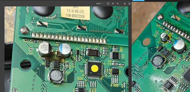
-
 Bild
Bild
Foto einer grünen Leiterplatte mit elektronischen Bauteilen
1111-016-01 N.L. SG1222ASJB-HB-6 ROHS 47 15V 112 151 C12 C13 C14 C15 C16 C17 C18 C19 C20 C21 C22 C23 C24 C25 C26 C27 C28 C29 C30 C31 C32 C33 C34 C35 C36 C37 C38 C39 C40 C41 C42 C43 C44 C45 C46 C47 C48 C49 C50 C51 C52
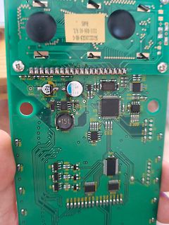
-
Thread
IC defekt oder nicht?
Trafo mit Mittelanzapfung, EINEN Brückengleichrichter und jeweils einen Spannungsregler für positive (L7815) und einen für negative Spannung (L7915) verwenden. Die Ladekondensatoren (C7/C9) wirken ETWAS übertrieben, falls nicht noch andere Lasten an den Spannungen dran hängen. Die Verwendung von 12V-Trafos
Rainer W. schrieb im Beitrag #7924447: > So ein L7815 besitzt einen typischen > Spannungsabfall (V_D Dropout voltage) von 2V. p.s. Die 2V gelten bei Nennstrom der Spannungsregler. Für niedrigeren Strom findest du die Werte als Graphik im Datenblatt
-
 Bild
Bild
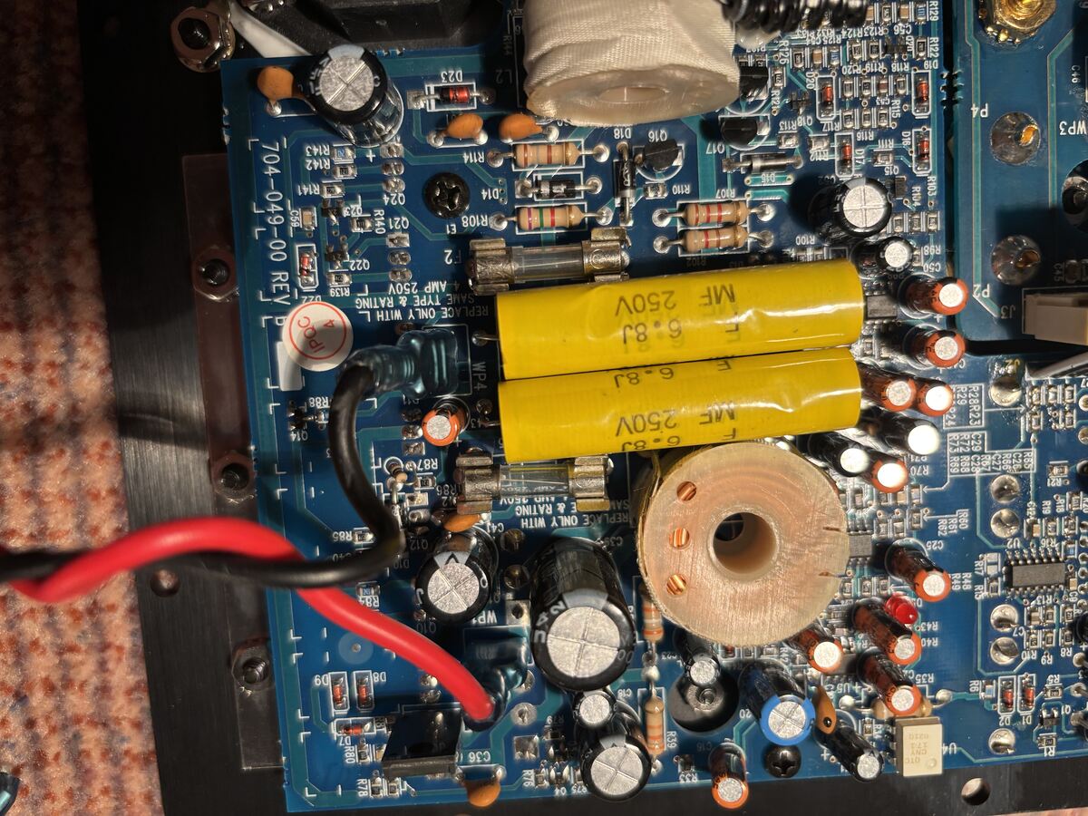
Nahaufnahme einer bestückten Leiterplatte mit Kondensatoren
704-049-00 REY, REPLACE ONLY WITH L, SAME TYPE & RATING, 250V, MF, 6-8J, 350V, R142, R143, R144, R108, R110, R107, R106, R105, R104, R103, R102, R101, R98, R97, R96, R95, R94, R93, R92, R91, R90, R89, R88, R87, R86, R85, R84, R83, R82, R81, R80, R79, R78, R77, R76, R75, R74, R73, R72, R71, R70, R69, R68, R67, R66, R65, R64, R63, R62, R61, R60, R59, R58, R57, R56, R55, R54, R53, R52, R51, R50, R49, R48, R47, R46, R45, R44, R43, R42, R41, R40, R39
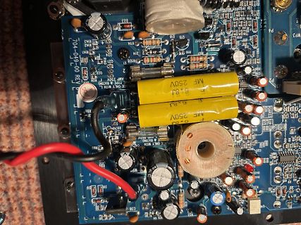
-
 Bild
Bild
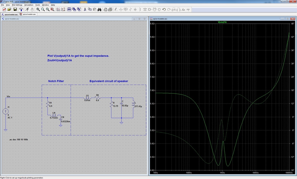
SPICE-Simulation Schaltplan und Frequenzgang eines Notch-Filters
Tools Window Help Notch Filter Equivalent circuit of speaker Vin AC 1 R1 6.9 LH 0.7122m CN 0.0322m L0 0.01m R 12.79 C 82.82p L 277.41p 10Hz 100Hz 1kHz 10kHz 100kHz
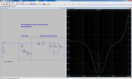
-
 Bild
Bild
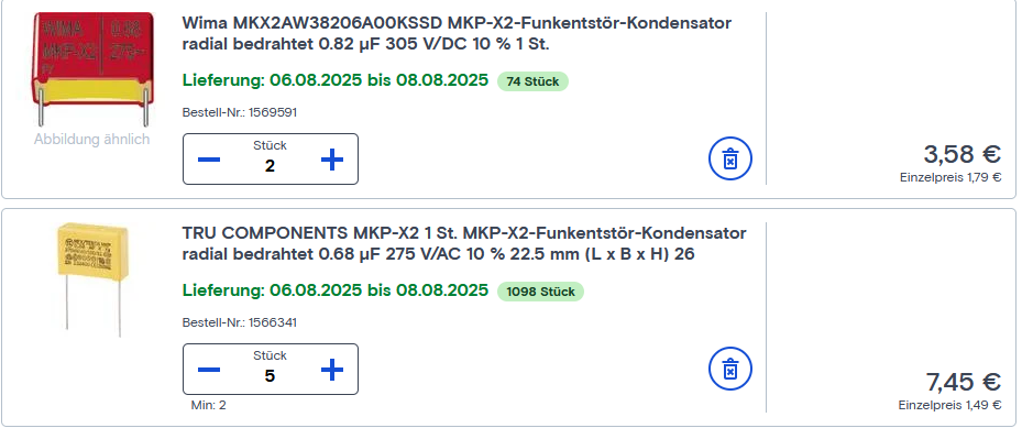
Online-Shop Produktliste für MKP-X2 Kondensatoren
St. Lieferung: 06.08.2025 bis 08.08.2025 74 Stück Bestell-Nr.: 1569591 Stück 2 3,58 € Einzelpreis 1,79 € TRU COMPONENTS MKP-X2 1 St. MKP-X2-Funkentstör-Kondensator radial bedrahtet 0.68 µF 275 V/AC 10 % 22.5 mm (L x B x H) 26 Lieferung: 06.08.2025 bis 08.08.2025 1098 Stück Bestell-Nr.: 1566341 Stück 5

-
Thread
"Radio-Buttons" in TTL/CMOS-Logik
Ausgänge, alles TTL-Level (0/5V) - Kurzer Druck auf Taste-1 -> Ausgang-1 wird+bleibt H, alle anderen L. - Kurzer Druck auf Taste-2 -> Ausgang-2 wird+bleibt H, alle anderen L. - usw. - Zustand beim einschalten egal, es soll aber nur 1 Ausgang H sein. - Ob die Taster gegen H oder L schalten ist egal
Ausgänge, alles TTL-Level (0/5V) > - Kurzer Druck auf Taste-1 -> Ausgang-1 wird+bleibt H, alle anderen L. > - Kurzer Druck auf Taste-2 -> Ausgang-2 wird+bleibt H, alle anderen L. > - usw. > - Zustand beim einschalten egal, es soll aber nur 1 Ausgang H sein. > - Ob die Taster gegen H oder L schalten
-
Thread
Wollen die Leute keine Glasfaser auf der letzten Meile mehr?
kostet 40 EUR/Monat. Das wäre ein akzeptabler Preis. Gab es damals (ca. 3 Jahre) nicht, 100MBit für 79,99€ Aber egal, für mich ist das Thema durch.
Falls Dir sowas wirklich mal begegnet ist, würde ich den Fehler weiter hinten vermuten, z.B. bei der L2TP-Übergabe zum Reseller.
-
 Bild
Bild
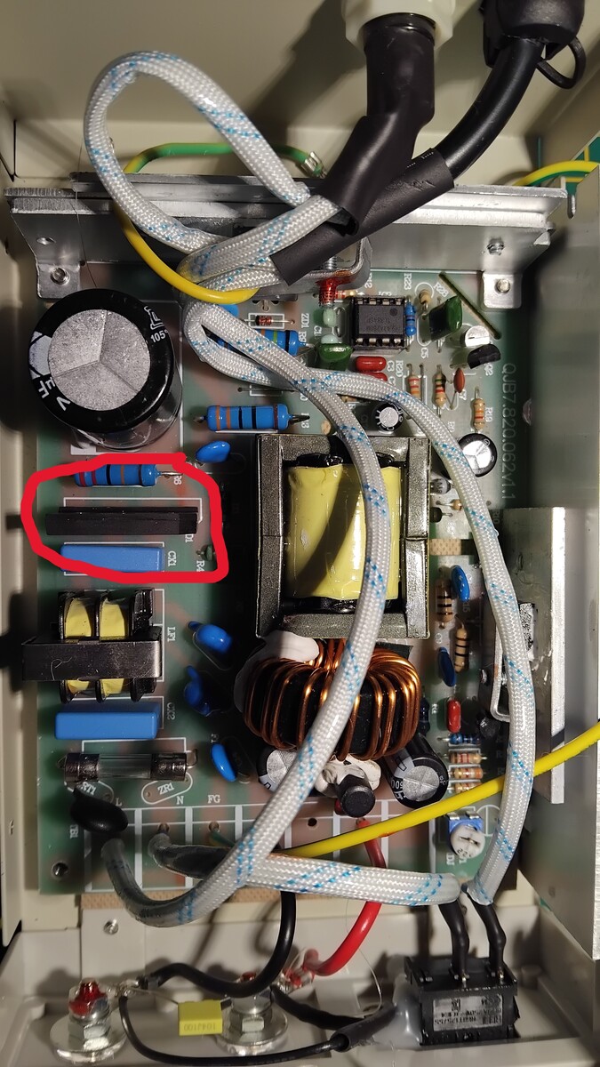
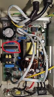
Innenansicht eines Schaltnetzteils mit Bauteilen
105, QUB7A206211, L1, L2, N, FG, R1, R2, R3, R4, R5, R6, R7, R8, R9, R10, R11, R12, R13, R14, R15, R16, R17, R18, R19, R20, R21, R22, R23, R24, R25, R26, R27, R28, R29, R30, R31, R32, R33, R34, R35, R36, R37, R38, R39,
-
Thread
Technisat Digitradio 371 ohne Ton
der richtige: https://www.ebay.de/itm/176669462559?_skw=3314+LEO&itmmeta=01M25KWBCNVTN263F5SQK7GY79&hash=item292252101f:g:o-gAAOSwo-JnLXt7&itmprp=enc%3AAQALAAAA8GfYFPkwiKCW4ZNSs2u11xCwAjH%2FX%2BOqB2PwhT4Ke5ZNK6vlqo0Kchs%2FkoL9m1ep158sFEneyPU9AjMO6S7fQTvzzVQHSvThBerkAVBVJ%2BAnI%2BxUJXhZIYCGVqd60lEcy
-
Thread
Getriebe konstruieren
61 31 66 --> 6.184331797235022 21 66 31 61 --> 6.184331797235023 22 31 18 79 --> 6.184343434343435 22 62 36 79 --> 6.184343434343435 22 79 18 31 --> 6.184343434343434 22 79 36 62 --> 6.184343434343434 24 62 33 79 --> 6.184343434343434 24 79 33 62 --> 6.184343434343433 28
83 15 38 --> 6.184313725490197 34 83 30 76 --> 6.184313725490197 36 62 22 79 --> 6.184343434343435 36 79 22 62 --> 6.184343434343435 44 62 18 79 --> 6.184343434343435 44 79 18 62 --> 6.184343434343434 45 57 17 83 --> 6.184313725490195 45 83 17 57 --> 6.184313725490196 51
-
Thread
Alberta zieht AKW in Betracht
https://www.ardmediathek.de/video/wetter-vor-acht/moderation-karsten-schwanke/das-erste/Y3JpZDovL2Rhc2Vyc3RlLmRlL2RhcyB3ZXR0ZXIgaW0gZXJzdGVuLzIwMjUtMDYtMTlfMTktNTAtTUVTWg
hier ist die Entscheidungshilfe wo man man besten anfängt: https://de.wikipedia.org/wiki/Liste_der_L%C3%A4nder_nach_CO2-Emission_pro_Kopf#L%C3%A4nderliste_der_CO2-Emissionen_pro_Kopf
-
Thread
Frage zu: Lipos in Reihenschaltung.
3,3 V und eine völlig andere Lade-/Entladecharasteristik. Aus den Kommentaren von Darius (blue_79) entnehme ich, dass er mit 'normalen' 3,6+ V Nennspannung arbeitet.
Julian L. schrieb im Beitrag #7896521: > Jörg R. schrieb: >> Das sind dann aber keine Lithium-Ionen-Akkus sondern LiFePO4 >> (Lithium-Eisenphosphat) Akkus..andere Chemie. > > Naja, im Prinzip sind das alles
-
Thread
Arduino: page-write in I2C eeprom verliert sporadisch ein Byte
tatsächlich isoliert läuft (in einem Minimalprogramm), ist > der Fehler verschwunden? Hallo S. l., richtig Viele Grüße Kai
6D 6E 6F 70 71 72 73 74 75 76 77 7. page-write: cnt 120 cur_byte 24 -> 144 status 0 written 78 79 7A 7B 7C 7D 7E 7F 80 81 82 83 84 85 86 87 88 89 8A 8B 8C 8D 8E 8F read 78 79 7A 7B 7C 7D 7E 7F 80 81 82 83 84 85 86 87 88 89 8A 8B 8C 8D 8E 8F 8. page-write: cnt 144 cur_byte 16 -> 160 status 0