-
PDF
16f88.pdf
SideBySideMicro.aspx M APS Microchip Advanced Part Selector Microcontroller Side-By-Side Comparison PIC16F1847 PIC16F1827 PIC16F88 Microchip Microchip Microchip delete delete delete P.Memory (Kbytes) 14 Flash 7 Flash 7 Flash P.Memory (Kwords) 8 4 4 Self-Write Flash Yes Yes Yes RAM (Bytes) 1024 384 368
-
Datei
polling.asm
------------------------------------------* ;Specifications: * ;========== * ;Processor: Microchip PIC 16F873 * ;Clock: 4,000 Mhz * ;Serial Rate: 19'200 baud, 8 bit, no parity, 1 stopbit * ;------------------------------------------------------------* ;Description: * ;======== * ;Software for the DSP
in „PIC16F873 USART Problem“ · Mikrocontroller und Digitale Elektronik ·
-
PDF
PIC-Intrrrupt.pdf
Overflow Interrupt Enable bit 1 = Enabled 0 = Disabled bit 0 ECCP1IE: CCP1 Interrupt Enable bit (2) 1 = Enabled 0 = Disabled Note 1: This bit is available in PIC18F4X80 devices and reserved in PIC18F2X80 devices. 2: This bit is available
in „PIC 18F2550 Interrupts in C18“ · Mikrocontroller und Digitale Elektronik ·
-
PDF
HORIBA_Schreibtisch_Rev1.1.pdf
3 1 2 5 IC2 R 2 8 S + - F 0 8 7 6 M2 1 4 ZF5,1D6 D B 7 "AUF" 6 PIC16F628SO R5 R4 PJ16B6 DIN-7POLS R3 4k7 100k 4k7 RING-CORE180VA2S T1 DIN-7POLR 10k RN4 D4 7 100k C5 TR1 T18535 1N4148 BU2 D7 4µ7/100V M1 R2
in „Höhenversllbarer Schreibtisch“ · Mikrocontroller und Digitale Elektronik ·
-
Datei
irmpconfig.h
IRMP_SUPPORT_DENON_PROTOCOL 1 // DENON, Sharp >= 10000 ~250 bytes // more protocols, enable here! Enable Remarks F_INTERRUPTS Program Space #define IRMP_SUPPORT_RC5_PROTOCOL 1 // RC5 >= 10000 ~250 bytes #define IRMP_SUPPORT_RC6_PROTOCOL 1 // RC6 & RC6A >= 10000 ~250 bytes #define IRMP_SUPPORT_JVC_PROTOCOL 0 // JVC >= 10000 ~150 bytes #define IRMP_SUPPORT_NEC16_PROTOCOL 0 // NEC16 >= 10000 ~100 bytes #define IRMP_SUPPORT_NEC42_PROTOCOL
in „IRMP - Infrared Multi Protocol Decoder“ · Projekte & Code ·
-
PDF
HORIBA_Schreibtisch_Rev51.3l.pdf
3 1 2 5 IC2 R 2 8 S + - F 0 8 7 6 M2 1 4 ZF5,1D6 D B 7 "AUF" 6 PIC16F628SO R5 R4 PJ16B6 DIN-7POLS R3 4k7 100k 4k7 RING-CORE180VA2S T1 DIN-7POLR 10k RN4 D4 7 100k C5 TR1 T18535 1N4148 BU2 D7 4µ7/100V M1 R2
in „Steuerung für höhenverstellbaren Schreibtisch“ · Projekte & Code ·
-
PDF
STM32F429_V1.2.pdf
P I U 2 0 8 4CKE1 P I U 1 0 1Q GNDQ P I U 1 0 2 8 P2 0.1uF PIC1801 PIC1802 VCPA_2 VSSA P I U 2 0 4 8 SDIO_DPIU20117 PC7 PH7 P I U 2 0 8 52 P I U 1 0 1 4 GND P I U 1 0 4 1 PASS_REG SDIO_DPIU20118 PC8 PH8 P I U 2 0 8 60
in „Hat jemand Erfahrungen mit diesem Board auf Ebay.“ · Mikrocontroller und Digitale Elektronik ·
-
PDF
EMS_PIC.pdf
/ 1 13 RC1/T1OSI RC6/TX/CK 16 GND GND RC0..7 5 3 14 RC2/CCP1 RC5/SDO 15 1 2 + 4 GND RC3/SCK/SCL RC4/SDI/SDA 3 4 RB7 GND 5 PIC18F2580-E/SO PIC18F2580-I/SP 5 6 RB6 6 7 8 RB5 9 10 V ISCP JP5 V + 1 2 IC9 +8
in „Buderus EMS-"Gateway" mit PIC18F / Sammelbestellung“ · Haus & Smart Home ·
-
PDF
AN955.pdf
Rectifier © 2005 Microchip Technology Inc. DS00955A-page 15 AN955 FIGURE A-2: BOARD SCHEMATIC, PART 1 (PIC18F4X31 MICROCONTROLLER, PCPWM ISOLATORS, CURRENT COMPARATOR AND ASSOCIATED PARTS) F 3 3 F 2 2 μ 1 1 2 1 I I 3 1 I I 4 1 I I C 0 H L C 0. H L C 0. H L V V V 5 5 5 + 9 + 2 + 2 K 3 K R 1 R 1 7 8 1
in „Raumzeigermodulation, PWM“ · Mikrocontroller und Digitale Elektronik ·
-
Datei
irmpconfig.h
-------------------------------------------- */ // typical protocols, disable here! Enable Remarks F_INTERRUPTS Program Space #define IRMP_SUPPORT_SIRCS_PROTOCOL 0 // Sony SIRCS >= 10000 ~150 bytes #define IRMP_SUPPORT_NEC_PROTOCOL 1 // NEC + APPLE >= 10000 ~300 bytes #define IRMP_SUPPORT_SAMSUNG_PROTOCOL
in „IRMP - Infrared Multi Protocol Decoder“ · Projekte & Code ·
-
PDF
STM32H7XX_M_schematics.pdf
G G DAT3 PIU502IO_D3 PC11 5V AMS1117-3.3V 3V3 1 0 ISP下载模式 PIC1PIC102 N3V3 PIJ102 1 CS PB12/CS PIJ4054 CMD PIU503IO_CMD PD2 3V3 P I U 1 VCCOUT P I U 1 0 2 GND 104 R1R1 NGND PIJ103 3 SDO PB14/MISO PIJ4066 Vcc PIU504 PIC501CO3C301 D CCC2PIC201PICC4C4
in „Problem mit USB auf STM32H743“ · Mikrocontroller und Digitale Elektronik ·
-
Datei
bauteile_004.txt
Bemerkung ------------------------------------------------------------------------------------- 500 S1M/11T SMD Vishay 100 4,00 2000 100nF/X7R 0603 100 1,00 Keramik-C 50 B140-7 Liteon 50 1,00 Shottky-Diode 400 LSGT677K SMD Osram 50 2,50 TOPLED 100 BAT54A SOT23 Fairchild 100 2,00 3600 BC807-40 SOT23 Infineon
in „Verkaufe diverse Bauteile“ · Markt ·
-
PDF
DoppelMagnetruehrer.PDF
PIC602 PIC601 P I J 3 0 1 ATxmega64A4U-AU 1 P I J 3 0 2 GND X1 10 pF P I J 3 0 3 GND X2X P I J 3 0 4 X032.768CO7 PIC702 PIC701 +3V3 +3V3 Molex 22-27-2041 10 pF P2 R101 JP3P 4k7 Vcc P I J P 3 0 2 D P0 D
in „Platine für Doppelmagnetrüher“ · Analoge Elektronik und Schaltungstechnik ·
-
Datei
leds_887.c
#define __16f887 #include <stdarg.h> #include <stdint.h> #include <stdio.h> #include "pic16f887.h" #include <pic14regs.h> #include <sdcc-lib.h> #define EXTRN_XTAL 0 #if (EXTRN_XTAL == 1) // externer Oszillator unsigned
in „SDCC & PIC16887: Fehler in erzeugter ASM-Datei“ · Mikrocontroller und Digitale Elektronik ·
-
Datei
bauteile_005.txt
Bemerkung ------------------------------------------------------------------------------------- 3 PIC18F252-I/SP DIL Microchip 3 4,00 Stückzahl Bauteil Gehäuse Hersteller VPE Preis/VPE Bemerkung ------------------------------------------------------------------------------------- 500 S1M/11T SMD Vishay
in „Verkaufe diverse Bauteile“ · Markt ·
-
Datei
tft.cpp
); FT8_cmd_dl(DL_COLOR_RGB | 0x00aaaaaa); FT8_cmd_dl(POINT_SIZE(25*16)); FT8_cmd_dl(TAG(11)); FT8_cmd_dl(VERTEX2F((LAYOUT_X1+(LAYOUT_W/2)),(LAYOUT_Y1+40+150))); FT8_cmd_dl(DL_COLOR_RGB | 0xaf0000); FT8_cmd_dl(POINT_SIZE(18*16)); FT8_cmd_dl(VERTEX2F((LAYOUT_X1+(LAYOUT_W
-
PDF
Last_board.pdf
A L C 5 _ U1 D O PIC32MZXXXXEC(E/F T P +UB 2 U 1 C ADC_1_NTC1_TEMP R31 50 1 AN17/ETXEN/RPE5/PMD5/RE5 AN18/ S ADC_2_NTC2_TEMPR17 50 2 AN16/ETXD0/PMD6/RE6 TRD3/SQID3/ERXCLK/EREFC +UB 1 ADC_3_NTC3_TEMPR30 50 3 AN15/
in „Schaltplankontrolle Last- + HMI-Board“ · Mikrocontroller und Digitale Elektronik ·
-
PDF
pb_digiconnectme9210-1281450_1_.pdf
I C v1.0 bus interface; 7-bitand10-bitaddressmodes FLEXIBLEINTERFACESUPPORT(FIM) UART, 1-Wire, USB device(low-speed),CANBUS WATCHDOGTIMER(16-BIT) Yes JTAG INTERFACE Available on developmentmodulesonly ON-BOARDPOWERSUPERVISOR
in „[V] 18St. DigiConnect ME9210 4/8 Modules for NET+OS (12€ St.)“ · Markt ·
-
PDF
pb_digiconnectme9210-1281450.pdf
I C v1.0 bus interface; 7-bitand10-bitaddressmodes FLEXIBLEINTERFACESUPPORT(FIM) UART, 1-Wire, USB device(low-speed),CANBUS WATCHDOGTIMER(16-BIT) Yes JTAG INTERFACE Available on developmentmodulesonly ON-BOARDPOWERSUPERVISOR
in „[V] 2St. neue DIGI-Connect ME Module "Seriell / Lan Umsetzter"“ · Markt ·
-
Datei
main.txt
*// // //*** Globale Variablen // //*****************************************// unsigned int uiTest1; unsigned int uiTest2; unsigned int uiADBackup; ///*********** Alte Daten vom PIC18F4550 ************** ///*********** Diese Daten werden nach nach erfolgreicher Initialisierung ncoh geloescht ******
in „LPC1769 USB einschalten“ · Mikrocontroller und Digitale Elektronik ·
-
PDF
STM32F746G_Discovery.pdf
PIC1601 PIC1602 100nF_X7R_10%_0402 PIU10C9 VDDQ VSSQ PIU10C1 100nF_X7R_10%_040PIC1701 PIC1702 P I U 1 VDDQ9 VSSQ P I U 1 0 D 1 C131 100nF_X7R_10%_0402 E1 E9 PIC13100nF_X7R_10%_0402 C282 PIUL1E1 VDDQ VSSQ
in „STM32F7 Discovery Board“ · Mikrocontroller und Digitale Elektronik ·
-
PDF
RF01_code.pdf
select crystal load capacitor x3 x2 x1 x0 load capacitor[pF] 0 0 0 0 8.5 0 0 0 1 9.0 0 0 1 0 9.5 0 0 1 1 10.0 …… …… 1 1 1 0 15.5 1 1 1 1 16.0 i2..i0:select baseband bandwidth i2 i1 i0 Baseband Bandwidth [kHz] 0 0 0 reserved 0 0 1 400 0 1 0 340 0 1 1 270 1 0 0 200 1 0 1 134 1 1 0 67 1 1 1 reserved dc:Disable signal output of CLK pin 3. Frequency Setting Command bit 15 14 13 12 11 10 9 8 7 6 5 4 3 2 1 0 POR 1 0 1 0 f11 f10 f9 f8 f7 f6 f5 f4 f3 f2
-
PDF
Schaltplan.pdf
ATmega128-16AI 1214,7456 MHz AGND COTP157 COC108 TP PIC108PIC10802 COR109 12pF PIR10PIR10901 GND GNDR AGND P O R E S E T D D Title 01-UC-ATMEL2.SchDoc Size Number Revision A3 1 Date: 09.11.2008 Sheetof File: G:\Design
in „V: Leiterplatten aus Überproduktion abzugeben“ · Markt ·
-
PDF
PICkit_3_Programmer_Application_User_s_Guide_50002158a.pdf
programming. Use a resistor to pull this pin low when programming. Some Mid-Range parts, such as the PIC16F72/73/74/76/77 family and PIC16F737/747/767/777 family require a minimum programming V DD of +4.75V. Depending on the USB voltage, the PICkit 3 may not be able to supply +4.75V on VDD. Program these parts using an external +5.0V power supply. Some PIC18F parts require significant bypass capacitance on V DD. Try increasing the total bypass capacitance up to 10 µF. PIC18FXXJXX, PIC24X, and dsPIC30F/33F devices require a 4.7 µF capacitor on the VDDCORE
in „PICkit3 und Windows 11“ · Mikrocontroller und Digitale Elektronik ·
-
Datei
Empf_nger2.asm
****************************************************************** ; ;Apple-Remote-Empfänger 2008 ;PIC16F84A 4Mhz ;Maximilian M. ;*********************************************************************** ; TSOP1738 ; |--| PortA,0 |----|PortB,0-5 ; | |------------|PIC |----------- ; |--| ----|16F | ; Quarz
in „PIC-IR-Empfänger HILFE!“ · Mikrocontroller und Digitale Elektronik ·
-
 Bild
Foto einer roten Leiterplatte mit Bestückungsdruck
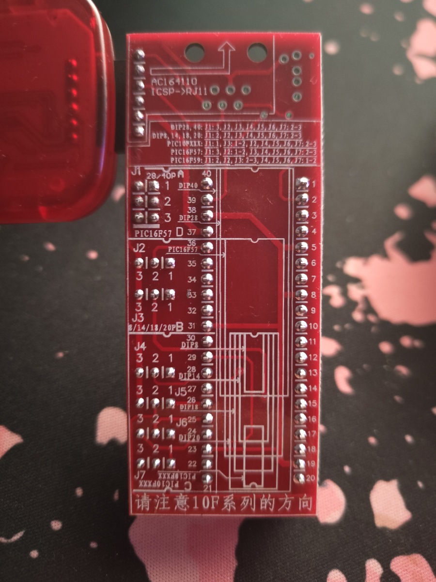
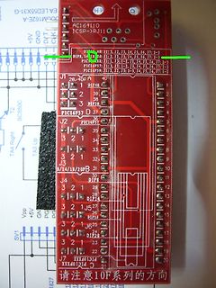
AC164110 ICSP->RJ11 DIP28, 40: J1, J3, J4, J5, J6, J7, J2-3 DIP8, 10, 18, 20: J1, J3, J4, J5, J6, J7, J2-3 PIC16F57: J1, J3, J4, J5, J6, J7, J2-3 PIC16F59: J1, J3, J4, J5, J6, J7, J2-3 J1 DIP40 2 39 2 38 3 DIP28 PIC16F57 D 37 J2 36 3 5 3 2 1 6 3 2 1 7 3 2 1 8 J3 31 8/14/18/20PB J4 30 DIP8 3 2 1 29 J5 27 3 2 1 28 3 2 1 26 DIP16 J6 25 3 2 1 23 DIP20 3 2 1 22 J7 XXX01014 XXX01014 C 请注意10F系列的方向
in „Ich benötige Hilfe beim beschreiben eines PIC12F629 IP“ · Mikrocontroller und Digitale Elektronik · · Platinenfotos
-
Datei
16F877A.H
// HEADER FILE #if !defined ICD_DEBUG && !defined ICD2_DEBUG #pragma chip PIC16F877A, core 14, code 8192, ram 32 : 0x1FF #elif defined ICD2_DEBUG #pragma chip PIC16F877A, core 14, code 0x1F00, ram 32 : 0x1FF // last 256 locations are reserved for debugging //RESERVED RAM LOCATIONS char ICD2R1 @ 0x70; char reservedICD2[11] @ 0x1E5; // reserved RAM for ICD2 #pragma stackLevels 7 // reserve one level for debugging #else /* ICD_DEBUG */ #pragma chip PIC16F877A, core 14, code 0x1F00, ram 32 :
in „Servomotor Steuerung per PIC“ · Mikrocontroller und Digitale Elektronik ·
-
PDF
Schaltplan.pdf
1 2 3 4 P2 PI Motor Treiber C8 C9 GND P11u PI 1u VM 3V3 25V 25V BRAKE DIR HALL_C A P A VM P IPCP0P0PPIPCP0P PPIPC 3 CI 3V3 P2 C15 DRV8350RSRGZT T1 PT T C14 P2100n P0CO1 PIC11 N F SC S C I SN D L H L PIC03
in „MOSFET für BLDC 18V“ · Analoge Elektronik und Schaltungstechnik ·
-
PDF
Grasshopper_Adapter_Rev.A.pdf
COC16 COP1 2 HPR PI25CODEC1029 PIC1601 PIC1602 P130CNCEC102 HPL PI27CODEC1025 100uF/6.3V PIP101 P140CNCEC1013 VGND PIU0CODEC1027 COC20 PIP102 PIU0CNCEC1014 PIP103 TSC2102IDA PIC2001 PIC2002 Header 3 100uF/
in „Grasshopper und TFT Display“ · Mikrocontroller und Digitale Elektronik ·
-
 Bild
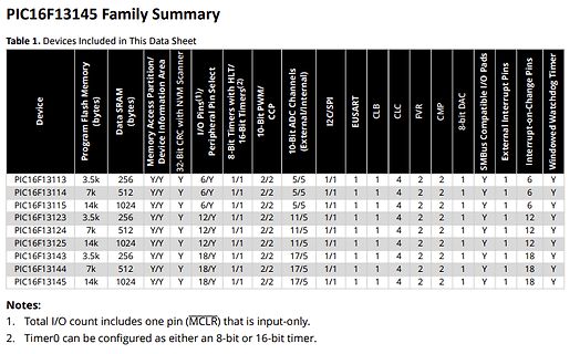
Tabelle der PIC16F13145 Familie Spezifikationen
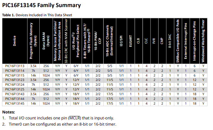
PIC16F13145 Family Summary Table 1. Devices Included in This Data Sheet Device, Program Flash Memory (bytes), Data SRAM (bytes), Memory Access Partition/Device Information Area, 32-Bit CRC with NVM Scanner
in „Microchip CLB – erste Versuche zur „FPGA-Zelle“ im Achtbitter“ · Mikrocontroller und Digitale Elektronik · · Screenshots
-
Datei
main.c
***************************** copyright (c) 2011 Title: RFM22B transciever simple example based on PIC C Current version: v1.0 Function: Package send Demo Processor PIC16F690S-20 Clock: 8MHz internal RC Operate frequency: 434MHz/869M/915M Data rate: 2.4kbps/4.8kbps/9.6kbps Working mode: PH+FIFO modulation
in „RFM22B Beispiel Projekt gesucht.“ · Mikrocontroller und Digitale Elektronik ·
-
Datei
lcd.c
correct delays, do not change this #define Display_On 12 #define Display_Off 8 #define Display_Clear 1 /***modify Ports if you are using another DsPic30F***/ #define RW LATEbits.LATE5 // LCD R/W signal pins #define RS LATEbits.LATE4 // LCD RS signal pins #define E LATEbits.LATE8 // LCD E signal pins /
in „LCD Display am PIC - verstädnisfrage BUS Übertragung“ · Mikrocontroller und Digitale Elektronik ·
-
Datei
Nixie_main_v3.c
feeds time display values to the shift registers (logic-level). * * Originally started with a 40-pin PIC18F4520 * but switched to a 14-pin PIC16F15325 to reduce overall pin count/size. * * Need an external crystal for final design (way more fucking accurate). * This code needs to produce a 44-bit number
in „Compiler Error beim Build für PIC16F15325“ · Mikrocontroller und Digitale Elektronik ·
-
Datei
Nixie_main_v3__-_Kopie.c
feeds time display values to the shift registers (logic-level). * * Originally started with a 40-pin PIC18F4520 * but switched to a 14-pin PIC16F15325 to reduce overall pin count/size. * * Need an external crystal for final design (way more fucking accurate). * This code needs to produce a 44-bit number
-
Datei
Bootldr.txt
different location. It is assumed that the downloaded user program has been compiled with HI-TECH PIC C and therefore these first four instructions simply implement a long jump. Below is a typical memory map with the bootloader installed. Microchip PIC 16F877 memory map with the bootloader installed
-
Datei
memory.h
Technology Inc. @File Name memory.h @Summary This is the generated header file for the MEMORY driver using PIC10 / PIC12 / PIC16 / PIC18 MCUs @Description This header file provides APIs for driver for MEMORY. Generation Information : Product Revision : PIC10 / PIC12 / PIC16 / PIC18 MCUs - 1.81.7 Device : PIC18F16Q41
in „MPLab X IDE und Hi-Tech Compiler PICC18“ · Mikrocontroller und Digitale Elektronik ·
-
PDF
Frequenzzaehler.pdf
mit einem externen TTL- (siehe Bild 1), die allerdings ebenfalls schnelVorteiler zu versehen. Das erhöht den Hard- sein soll, um die Zähleigenschaften des PIC wareaufwand und begrenzt die Maximalfre- nicht zu degradieren. PIC's gibt es in
in „PIC - Frequenzzähler weit über 50 MHz auf die minimalistische Art“ · Mikrocontroller und Digitale Elektronik ·
-
PDF
AN2662-Sensorless-Drive-forSingle-and-Two-PhaseBLDC-Motor-00002662A.pdf
desc®ibes how to implement a sensorless control for single and two-phase BLDC motors using the 8-bit PIC microcontroller. The implementation is based on the low-cost PIC16F153XX family of microcontrollers and hardware BEMF filtering in a cooling fan application. The application is tested on a 80 mm x 80
in „EBM-Papst EC Motor“ · Analoge Elektronik und Schaltungstechnik ·
-
Datei
debounce.html
<HTML><HEAD> <TITLE>PIC De-bouncing </TITLE> </HEAD> <BODY> <H1 Align="Center">PIC De-bouncing</H1> <P></P> <P>Debouncing; What is it and what is used for? Well, if you ever looked at the current through (or the voltage across
in „Vertikale Counter“ · Mikrocontroller und Digitale Elektronik ·
-
Datei
bootload.asm
FOR SPECIAL, INCIDENTAL OR ; CONSEQUENTIAL DAMAGES, FOR ANY REASON WHATSOEVER. ; ; ; Bootloader for PIC16F by Rodger Richey ; Adapted from PIC18F bootloader developed by Ross Fosler ; 03/18/2002 ... First full implementation ; 03/25/2002 Modified receive & parse engine to vector to autobaud on a checksum
in „Bootloader über MPLAB“ · Mikrocontroller und Digitale Elektronik ·
-
PDF
91055b.pdf
the best understanding of USB, read the briefs in order: TB054, TB055, TB056, TB057, TB058 FIGURE 1: PS/2 TO USB MOUSE TRANSLATOR HARDWARE DIAGRAM PIC16C745/765 C1** OSC1 VUSB C3 200 nF C2** XTAL 6 MHz Host OSC2 R1 1.5k PS/2 Female USB Cable 100 Ω D- D- Clock D+ D+ 6 5 5 Data RC0 VSS * C4 Gnd 4 3 3 RC1 +5VDC 4 0.1 µF 2 1 1 VDD * *Note: There are twoSS and VDD pins on PIC16C765. **Note: C1 and C2 values selected according to crystal load capacitance. 2002 Microchip Technology Inc. Preliminary DS91055B-page
in „MC mit USB Interface“ · Mikrocontroller und Digitale Elektronik ·
-
Datei
bauteile_006.txt
Bemerkung ------------------------------------------------------------------------------------- 3 PIC18F252-I/SP DIL Microchip 3 4,00 Stückzahl Bauteil Gehäuse Hersteller VPE Preis/VPE Bemerkung ------------------------------------------------------------------------------------- 500 S1M/11T SMD Vishay
in „Verkaufe diverse Bauteile“ · Markt ·
-
Datei
spi_2_lcd.asm
---------------------------------------------- ; Autor: Adrian Kauz ; Datum: 20.10.2008 ; Version: 1.1 ; PIC: 16F87A @ 8Mhz ; Funktion: Über den SPI-Bus das Display EA-DOGL128X6 ansteuern. ; Die Befehle werden per RS232 gesendet und vom PIC ; an das Display weitergeleitet. ; Update: RA4 Port als Display-Reset benutzt ; Initialisierung geschieht über den PIC ;------------------------------------------------------------------ LIST P=16F876A include <p16f876a.inc> ;------------------------------------------------------------------ ; GRUNDKONFIGURATIONEN DES
in „Ansteuerung des ST7565R via PIC-16F87A (Assembler)“ · Mikrocontroller und Digitale Elektronik ·
-
Datei
i2c.c
// Datei: i2c.c // Für: µC = PIC16F1704 // Zweck: Definiert I2C-Bus-Funktionen #include "PROJECT.H" // *** INFO ******************************** // Interrupt-Flags werden gesetzt auch wenn kein Interrupt benutzt wird. Damit // sie
in „I2C Initialisierung (Master) PIC16F1704“ · Mikrocontroller und Digitale Elektronik ·
-
Datei
lcd.c.txt
# pragma chip PIC16F84A # pragma char LCD_DATA @ PORTB # pragma char LCD_DATA_TRIS @ TRISB # pragma char LCD_CTRL @ PORTA # pragma char LCD_CTRL_TRIS @ TRISA # pragma bit LCD_E @ LCD_CTRL. 4 # pragma bit LCD_RS @ LCD_CTRL
in „ansteuerung eines LCD mit PIC“ · Mikrocontroller und Digitale Elektronik ·
-
 Bild
Foto einer roten Leiterplatte mit Bestückungsdruck
AC164110 ICSP>RJ10 DIP6, 14 DIP5, 12, 10, 8, 6, 4, 2 PIC16F57 J1 28-40p 1 2 3 39 38 37 36 J2 PIC16F57 3 2 1 35 34 33 32 31 J3 8/14/18/20PB 30 DIP8 J4 3 2 1 29 28 DIP14 3 2 1 J5 27 26 DIP10 3 2 1 J6 25 24 DIP20 3 2 1 J7 23 22 21 PIC16F57 XXXX 10F系列的方向
in „PIC Programmieren“ · Mikrocontroller und Digitale Elektronik · · Platinenfotos
-
PDF
01006a.pdf
AN1006 Interfacing SPI™ Serial EEPROMs to PIC18 Devices This application note provides assistance and source Author: Martin Kvasnicka code to ease the design process of interfacing a Microchip Technology Inc. Microchip PIC18F1220 PICmicro ® microcontroller
in „Infineon µC XC164D-Serie“ · Mikrocontroller und Digitale Elektronik ·
-
Datei
keylcd.asm
xw2 ; clrf xw3 movlw D'100' movwf temp add100malI: ; call Add32 call Add16 ; f16 =f16 + xw16 decfsz temp,F goto add100malI movfw f0 movwf Year_Low movfw f1 movwf Year_High ; kann man hier auf div mod 16 wechseln? ; DivMod(D, D4, I=Q, D=F); movfw d0 movwf f0 movfw d1 movwf f1
in „Noritake VFD GU140x32F7806 4-Bit Mode, Initialisierung“ · Mikrocontroller und Digitale Elektronik ·
-
PDF
mt6_06.pdf
PIC16F84 program connector Header SL1-6 J22 PS/2 connector Molex 87123-08 J23 Uninterruptible Power Supply Header SL2-10 (UPS) connector J24 MultiMediaCard (MMC) connector JST Drawing No. KRD-24511-1 (optional
in „CAN-Bus Ansteuerung über C# - Compact Framework“ · Softwareentwicklung ·
-
PDF
eGC.pdf
DISP_G[ ..7] DISP_R6 DPIIC20IO_L31P_A19_M1CKE_1 PIDISP1012R7 DISP_R7 DPIIC20D16 R7 DISP_G0 F13 IO_L31N_A18_M1A12_1 13 DISP_G0 DISP_G1 F14IC20IO_L32P_A17_M1A8_1 G0 PIDISP1013 NLDISP0G PIIC20IO_L32N_A16_M1A9_1 G1 PIDISP1014G1 DISP_G2 CPIIC20IO_L33P_A15
in „[Suche] Interessierte(n) an Projekt (ARM/FPGA)“ · Mikrocontroller und Digitale Elektronik ·