Format: BS (08) Function: Writing position shifts left by one digit. Fonts displayed stay displayed at the time. If writing position is at the leftmost position, nothing happens. Example) LIUST-51 A B C D EF G H I J K L M N O P Q R S T *1 Liu_outb(0x8); A B C D EF G H I J K L M N O P Q R S T 2) Line feed
information. Such information can be obtained through a local Representative, by visiting our website at www.te.com, or by calling PRODUCT INFORMATION or the TOOLING ASSISTANCE CENTER at the numbers at the bottom of page 1. 2.3. Drawings Customer Drawings for product part numbers are available from the
range, otherwise specifications are At T5°C. (Note 4) SYMBOL PARAMETER CONDITIONS MIN TYP MAX UNITS LOGIC INPUTS (CLK, OE, SHDN, MUX) VIH High Level Input Voltage VDD = 3V ● 2 V VIL Low Level Input Voltage VDD = 3V ● 0.8 V I Input Current
sdc zu sein und da gibt es ein Problem was wohl auch Clonezilla hat und weshalb W10 nix macht: [c] jv@JamesWebb:~$ blkid /dev/sda1: UUID="1ac71602-89cf-4c83-9a0a-99762e13e79c" BLOCK_SIZE="4096" TYPE="ext4" PARTUUID="7f4322d5-01" jv@JamesWebb:~$ jv@JamesWebb:~$ lsblk -f NAME FSTYPE FSVER LABEL
sudo] password for jv: mount: /media/jv: can't read superblock on /dev/sdc. jv@JamesWebb:~$ [/c]
offered in space-saving packages. The W25Q128JV array is organized into 65,536 programmable pages of 256-bytes each. Up to 256 bytes can be programmed at a time. Pages can be erased in groups of 16 (4KB sector erase), groups of 128 (32KB block erase), groups of 256 (64KB block erase) or the entire chip
connected. Integrated Silicon Solution, Inc.- www.issi.com 9 Rev. L9 02/20/2022 IS25LP128 3. BLOCK DIAGRAM C o tolLogi HighV olageG enertor Sttus IO Bufersand Registr D at Lathes C E# 256B yes Page Bufer e SC K c r t W P# l (O2) r Y - ec der h SI r (O0) e l SO r (O1) S (1) HO LD# orRES ET# r (IO3) d o e M emoryArray
AREA 5.15 4.85 SIDE WALL LEAD METAL THICKNESS DIM A 0.8 0.7 OPTION 1 OPTION 2 C 0.1 0.2 SEATING PLANE 0.05 0.00 0.08 C 2X 3.5 (DIM A) TYP 3.45 0.1 (0.2) TYP 9 16 EXPOSED THERMAL PAD 28X 0.5 8 17 2X SYMM 3.5 33 0.30 32X 0.18 1 24 0.1 C A B 0.05 C PIN 1 ID 32 25 (OPTIONAL) SYMM 0.5
(-40°C to +105°C) valid part numbers: PACKAGE TYPE DENSITY PRODUCT NUMBER TOP SIDE MARKING F SOIC-16 300mil 256M-bit W25Q256JWFJQ Q256JWFJQ P 256M-bit W25Q256JWPJQ Q256JWPJQ WSON-8 6x5-mm E 256M-bit W25Q256JWEJQ Q256JWEJQ WSON-8 8x6mm - 95 - W25Q256JW W25Q256JW-IM (2(-40°C to +85°C) valid part numbers: PACKAGE TYPE DENSITY PRODUCT NUMBER TOP SIDE MARKING F 256M-bit W25Q256JWFIM 25Q256JWFM SOIC-16 300mil P WSON-8
S D D D D D D D D D D X X X X T R V V A V A A A A V A V A A A A A A A V A A A C X L V C L V V L L V M M M M V V M M M M M M M M M M D D P P C C MB86277 MINT Graphics Controller 26 Specifications Rev. 1.0 FUJITSU LIMITED PRELIMINARY and CONFIDENTIAL 2.2.2LQFP256 Pin assignment table
c te r- 2 8 M H z o r less at 70 M Hz at 170 M H z at 470 M Hz 800 MHz to 900 MHz is tic M ore than 40 dB M ore than 30 dB M ore than 30 dB M ore than 30 813 M ore than 30 dB at at 27 M Hz at 80 M Hz at
humidity AH 70 g/m3 Ta> 70 C Note5 Note6 Note1: D0+/-, D1+/-, D2+/-, D3+/-, CK+/- Note2: DPS, FRC Note3: Measured at center of LCD panel surface (including self-heat) Note4: Measured at center of LCD module's rear shield surface (including self-heat) Note5: No condensation Note6: Water amount at Ta= 70°C and RH= 36% PRELIMINARY DATA SHEET DOD-PD-1288 (2nd edition) 7 NL6448BC33-63D 4.3 ELECTRICAL CHARACTERISTICS 4.3.1 LCD panel signal processing board (Ta= 25 C) Parameter Symbol min. typ. max
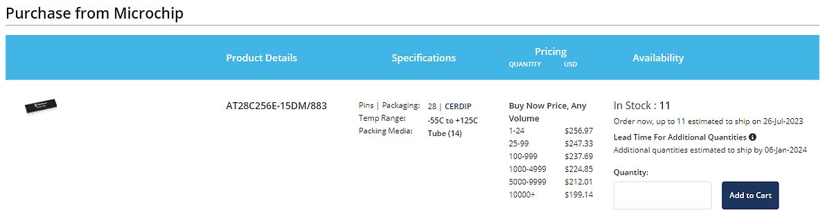
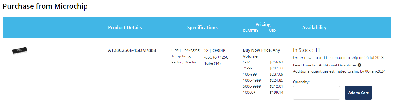
Wie kommen diese Mondpreise zustande? https://www.mouser.de/ProductDetail/Microchip-Technology/AT28C256E-15DM-883?qs=XGin%2Fqaz1Ki%252BvF6XM11FJg%3D%3D Das Teil ist noch eines der günstigeren Varianten.
ja auch eher zu günstig. Eher diese Variante für 420€: https://www.microchipdirect.com/product/AT28C010-15FM/883
der 5 Typen nicht genug nachgefragt werden und wieder hinten runterfallen. Ich bin bereits mit den AT89S8252, AT89C51RE2, P87C751, P89C668 auf die Nase gefallen.
4432 and SLE 4442) The command reads out the contents of the main memory (with LSB first) starting at the given byte address (N = 0…255) up to the end of the memory. After the command entry the IFD has to supply sufficient clock pulses. The number of clocks is m = (256 – N) × 8 + 1. The read access to
settings) EDGE Mode EDGE IDLE The module is ready for EDGE data transfer. No data sending or receiving at this time. The power SLM750 Module Hardware Design Page 28, total 84 pages MeiG Product Manual of SLM750 Module consumption is decided by net setting and related settings of EDGE. (For example, multi
, C2 (#10373, 1c69929) • MSPI: Fixed timing tuning issue for 80MHz Octal PSRAM on ESP32S3, which would lead to system stall at early stage (34e5a80) • MSPI: Fixed timing turning issue on high
S3 (3b62bf5) • Fixed POWER ON reset when using RTC IO as input in deepsleep on ESP32-S2/ESP32-C3/ESP32-C2 (cfcb573) • Fixed RTC memory lost in high temperature in deepsleep on ESP32-S2/ESP32-C3 (cfcb573) • Support 8MD256 as RTC slow clock work properly ESP32-S2/ESP32-C3/ESP32-C2/ESP32
(SMBus) 2-wire protocol. The data available VSSD 11 28 SR1 include the battery’s remaining capacity, temperature, SAFE 12 27 SR2 voltage, current, and remaining run-time predictions. N/C 13 26 MRST The bq2085 provides LED drivers and a push-button N/C 14
=CD=43mm Distance HI=GF=41mm Distance HA=GE=60mm Distance HB=GD=80mm Distance HC=GC=123mm Gap at HG=5mm Bend diameter BI=DF=25mm B C D /--------------|--------------\ A E \-------------| |-------------/ I H G
=CD=43mm Distance HI=GF=40mm Distance HA=GE=60mm Distance HB=GD=80mm Distance HC=GC=123mm Gap at HG=5mm Bend diameter BI=DF=25mm B C D /--------------|--------------\ A E \-------------| |-------------/ I H G
erreichbar. Hast Du eigene Zahlen, die mehr als 2..2,5 belegen? Wasser/Wasser Wp mit Wärmequelle 10°C und Heizwasser 35°C, da hat man locker einen COP von 4! Ich hab eine Sole-WP 3,5kW elekt.: Bei einer SoleTemp von -5°C gibt das bei 35°C Heizwasser 13,5 kW, bei SoleTemp von -0°C sind es dann 14,2kW
aus Süddeutschland Eher zwischen Hanau und Bremen. https://de.wikipedia.org/wiki/Deutsche_M%C3%A4rchenstra%C3%9Fe
Fuer > wahnsinnig schnell hab ich noch einen C128D mit einer internen 1571. Der Geheimtipp, nochmal fuer Alle: Mann muss nur die C= Taste beim Einschalten gedrueckt halten, dann bleibt die 1571 auch im C64-Modus eine > wahnsinnig schnelle
Marci W. schrieb im Beitrag #7431522: > Bist Du da sicher? Ja, Inserat aus einer zeitgenössischen c't.
P0 10 5 10 0 0 −3 −2 −1 0 1 2 3 −0.05 0 0.05 0−g level drift (mg/ C) sensitivity drift (%/deg. C) Figure 20. Y axis 0-g level change vs Figure 21. Y axis sensitivity change Vs temperature at 2.5V temperature at 2.5V 35 60 30 50 )25 ) ( (0 r r a20 a f 30 t t c15 c e e P10 P0 5 10 0 0 −3 −2 −1 0 1 2 3 −0.05 0 0.05 0−g level drift (mg/ C) sensitivity drift (%/deg. C) Figure 22. Z axis 0-g level change vs Figure 23. Z axis sensitivity change vs temperature at 2.5V temperature at 2.5V 35 60 30 50 )25 ) ( (0 r r p20 p o o0 n15 n c c e 20
[5:0] * * B5 B4 B 3 B2 B 1 B0 Color B: B[5:0] same as above (RESET = 111111b) 0 C[5:0] * * C5 C4 C 3 C2 C 1 C0 Color C: C[5:0] same as above (RESET =111111b) Note: color D pulse width is fixed at 64 clocks pulse. SSD1303 Rev 2.6 P 25/57 Oct 2007 Solomon Systech D/C Hex D7 D6 D5 D4
: 0 (no) ReservedMBZ : 0x00 Flags : 0x00 DevIsOpAtSsOrHigher : 0 (Is not operating at SuperSpeed or higher) DevIsSsCapOrHigher : 0 (Is not SuperSpeed capable or higher) DevIsOpAtSsPlusOrHigher : 0 (Is not operating at SuperSpeedPlus or higher
pins for channel status data. ! Microcontroller and Standalone Modes The CS8415A is available in a 28-pin TSSOP and SOIC ! Differential Cable Receiver package in both Commerical (-10 to +70°C) and Indus- ! On-chip Channel Status and User Data Buffer trial grades (-40 to +85° C). The CDB8415A Customer
auto+...' is implicitly enabled to detect SATA disks. Use '-d scsi+cciss,N' to disable it. To look at disks behind HP Smart Array controllers, use syntax such as: smartctl -a -d cciss,0 /dev/cciss/c0d0 (cciss driver under Linux) smartctl -a -d cciss,0 /dev/sg2 (hpsa or hpahcisr drivers under Linux) hpt
fuses for the CPU to run at 8 MHz, check irmp-main-avr.c for correct values for an ATMEGA88. Scanning Unknown IR Protocols. To enable logging in IRMP, modify the value of IRMP_LOGGING to 1 of irmpconfig.h on the line When logging

 Bild
Bild