temperature –40 85 °C A 6.4 Thermal Information PCF8574 THERMAL METRIC (1) DGV DW N PW RGT RGY UNIT 20 PINS 16 PINS 16 PINS 20 PINS 16 PINS 20 PINS θ Junction-to-ambient thermal resistance 92 57 67 83 53 37 °C/W JA (1) For more information about traditional and new thermal metrics, see the IC Package
data set-up time 250 - 100 [5] - 50 - ns n SU;DAT R o tr rise time of both SDA and SCL signals - 1000 20 300 - 120 ns e e . n tf fall time of both SDA and SCL - 300 20 × 300 20 × 120 [8] ns 6 i [3][6][7][8] [9] — o signals (VDD / 5.5 V) (VDD / 5.5 V) 4 m t set-up time for STOP condition 4.0 - 0.6 - 0.26
please see the Microchip Packaging Specification located at http://www.microchip.com/packaging 2X 0.20 H D D 2 A D N E 2 E2 E1 E 2X 0.20 H 2X 4 TIPS NOTE 1 1 2 0.25 C e B TOP VIEW A 8X A2 0.10 C A SEATING PLANE A1 8X b C A 0.25 C A-B D SIDE VIEW SEE DETAIL B H VIEW A–A Microchip Technology Drawing C04
Ratio V = 40V to 20V, V = −40V, 120 85 dB (min) V CM = 0V, o = 0 mA V = 40V, V = −40V to −20V, 105 85 dB (min) V = 0V, I = 0 mA CM o CMRR (8) Common Mode Rejection Ratio V = 60V to 20V, V = −20V to −60V, V = 20V to −20V
typical value 4800 4600 min Tj = 25 °C to 150 °C min Tj = -40 °C to 150 °C 4400 4200 4000 5 10 15 20 25 IOUT (A) Figure 10. Maximum current sense ratio drift vs load current (1) dk/k(%) 20 15 10 5 0 -5 -10 -15 -20 5 10 15 20 25 OUT(A) 1. Parameter guaranteed by design; it is not tested. Doc ID 15994
0.4 1.27 0.015 0.050 M 0.6 0.023 F 8 (max.) 12/14 1 VNS1NV04D SO-8 TUBE SHIPMENT (no suffix) B C Base Q.ty 100 Bulk Q.ty 2000 Tube length (± 0.5) 532 A A 3.2 B 6 C (± 0.1) 0.6 All dimensions are in mm. TAPE AND REEL SHIPMENT (suffix “13TR”) REEL DIMENSIONS Base Q.ty 2500 Bulk Q.ty 2500 A (max) 330 B (min) 1.5 C (± 0.2) 13 F 20.2 G (+ 2 / -0) 12.4 N (min) 60 T (max) 18.4 All dimensions are in mm. TAPE DIMENSIONS According to Electronic Industries Association (EIA) Standard 481 rev. A, Feb 1986 Tape width W 12 Tape Hole Spacing
Sieht wohl so aus. Wird z.B. hier erläutert: https://community.infineon.com/t5/Knowledge-Base-Articles/Queries-on-BLE-Qualification-and-Declaration-Processes/ta-p/259951#.
https://www.we-online.com/catalog/media/o662703v410%20ANR027_Bluetooth_Listing_Guide.pdf#page16 Hier bei Würth steht einiges dazu. Die Vertreter sind diesbezüglich auch sehr gut geschult bzw. stellen den Kontakt zu den Spezialisten her. Bei euren 100.
rev.0 AP ID register 0x34770008 Type is MEM-AP AHB5 with enhanced HPROT [L01] MEM-AP BASE 0xe00ff003 Valid ROM table present Component base address 0xe00ff000 Peripheral ID 0x04000bb4c9 Designer is 0x23b, ARM Ltd Part is 0x4c9, Unrecognized Component class
unterstützt wird. Vielleicht ist es einfach auch nur verbuggt gerade: [code] SEGGER J-Link Commander V8.20 (Compiled Mar 12 2025 12:22:42) DLL version V8.20, compiled Mar 12 2025 12:21:38 [/code]
des MCU MSPM0C1104 sind auf TI.com erhältlich. • Der Preis des Bausteins im WCSP-Gehäuse beträgt -,20 US-Dollar (ab 1.000 Stück) • Es stehen mehrere Bezahl- und Versandoptionen zur Auswahl. • Das MSPM0C1104 LaunchPad™ Development Kit kann auf TI.com für 5,99 US-Dollar erworben werden. [/c]
hardware socket communication at the same time Internal 32Kbytes Memory for Ethernet Tx/Rx Buffers 10BaseT/100BaseTX Ethernet PHY embedded Support Auto Negotiation (Full and half duplex, 10 and 100-based) Up to 12 communication interface 2 x I2C interfaces(support SMBus/PMBus) 5(W55MH32L) / 3(W55MH32Q
073A — 5 Peak Transient Input Current (50% duty cycle, 1-ms pulse width) I mA FPK HCPL-4701/4731 — 20 HCPL-070A/073A — 10 Reverse Input Voltage V — 2.5 V R Input Power Dissipation (Each Channel) PI — 15 mW Output Current (Each Channel) IO — 60 mA Emitter Base Reverse Voltage (HCPL-4701/070A) V EB — 0.5
over operating free-air temperature range (unless otherwise noted)(1) MIN MAX UNIT VIN1, VIN2 EN –0.3 20 V VBST –0.3 26 V VBST (10 ns transient) –0.3 28 V Input voltage range VBST (vs SW1, SW2) –0.3 6.5 V VFB, VO, SS, PG –0.3 6.5 V SW1, SW2 –2 20 V SW1, SW2 (10 ns transient) –3 22 V Output voltage range
are rectified and stored in the 5 μF capacitor. This potential is fed to the base of Q3. Q3's collector current will vary with the difference between its base and emitter voltages. Since the emitter voltage is fixed by the LM313 1.2V reference, Q3 performs a comparison function and
are rectified and stored in the 5 μF capacitor. This potential is fed to the base of Q3. Q3's collector current will vary with the difference between its base and emitter voltages. Since the emitter voltage is fixed by the LM313 1.2V reference, Q3 performs a comparison function and
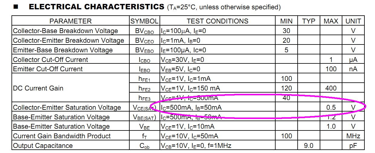
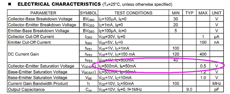
(TA=25°C, unless otherwise specified)
PARAMETER SYMBOL TEST CONDITIONS MIN TYP MAX UNIT
Collector-Base Breakdown Voltage BVcbo Ic=100uA, IE=0 30 V
Collector-Emitter Breakdown Voltage BVceo Ic=1mA, IB=0 20 V
Emitter-Base Breakdown Voltage BVEBO IE=100uA, Ic=0 5 V
Collector Cut-Off Current Icbo VCB=30V
UA 3.3V\25° working current 灵敏度阈值 不可调节 V SENS 110 UV Sensitivity threshold unadjustable 工作温度 W ST -20 70 ℃ working temperature 输出 Output 输出低电流 OL -5 5 mA Output Low Current 封锁时间 不可调节 2.3 S Lock Time unadjustable 延迟时间 不可调节 1 S Delay Time unadjustable 地址:惠州市惠城区潼侨镇宏村宏川路鑫永诚科技园 3 /9 电话(Tel):0752—7987222 网址
Daten: - Maximum DC Current Gain (hFE) is 400 - Continuous Collector current (IC) is 700mA - Base- Emitter Voltage (VBE) is 5V - Collector-Emitter Voltage (VCE) is 20V - Collector-Base Voltage (VCB) is 30V Die Lampe läuft mit 5V/250mA. Der Output des PIR Sensors ist 3,3V Meine Berechnungen
heißt HC-SR312 mit > einem AM312 Sensor. https://www.image.micros.com.pl/_dane_techniczne_auto/cz%20am312.pdf
www.ovaga.com/blog/transistor/2n6027-transistor-datasheet-pinout-equivalent-and-uses#:~:text=2N6027%20Transistor%20Uses,-The%202N6027%20transistor&text=By%20generating%20precise%20and%20stable,delay%20circuits%20and%20pulse%20generators. Gerhard
sich solch einen PUT auch leicht aus einem pnp- und einem npn-Transistor zusammenkleben: Einfach die Basen des Einen mit dem Kollektor des jeweils Anderen verbinden. Ein echter UJT funktioniert aber anders als diese PUT. Insbesondere hat er tatsächlich nur eine einzige Sperrschicht etwa in der Mitte
Length direction 0.175 Poisson's Ratio — ASTM D3039 B. Cross direction 0.143 Moisture Absorption 0.20 % 2.6.2.1A Flammability (Laminate & laminated prepreg) V-0 Rating UL 94 Relative Thermal Index (RTI) 130 °C UL 796 https://www.isola-group.com/pcb-laminates-prepreg/is410- fr-4-epoxy-laminate-and-prepreg
Oliver S. (oliverso) 24.02.2025 13:20 >Kein new verwendet. C++ hat Container, die übernehmen das. Wenn's >wirklich keine vollständige C++-stdlib gibt, das ganze Konzept >überdenken. Ich will das Ganze auf einem Atmega328 mit 2K
Derived1> (... /* Konstruktor-Parameter für Derived1 */); // virtuelle Funktionen aufrufen for (Base& obj : counters) obj.current ().exec (); // Alle löschen counters.clear (); }[/c]
Input Signal Frequency (kHz) Si8931 Si8932 Figure 19. Si8931 Total Harmonic Distortion (dB) vs. Figure 20. Total Harmonic Distortion (dB) vs. Input Signal Amplitude (V) Input Signal Frequency (kHz) 3 3 2 2 ) 1 ) 1 V V ( ( e e f 0 f 0 t t u u I I -1 -1 -2 -2 -3 -3 -40 -20 0 20 40 60 80 100 120 3.0 3.5 4.0
supply: +3.3V, +5V, 3VSB Power and Environment Power Requirement Standard 24-pin ATX power supply (20-pin is compatible) or 9~24V DC input Dimension 146 (L) x 203 (H) mm Temperature Operating within 0 ~ 60Ċ Storage within -20 ~ 85Ċ Ordering Code LE-575X Intel Atom processor with onboard VGA, Mini PCI
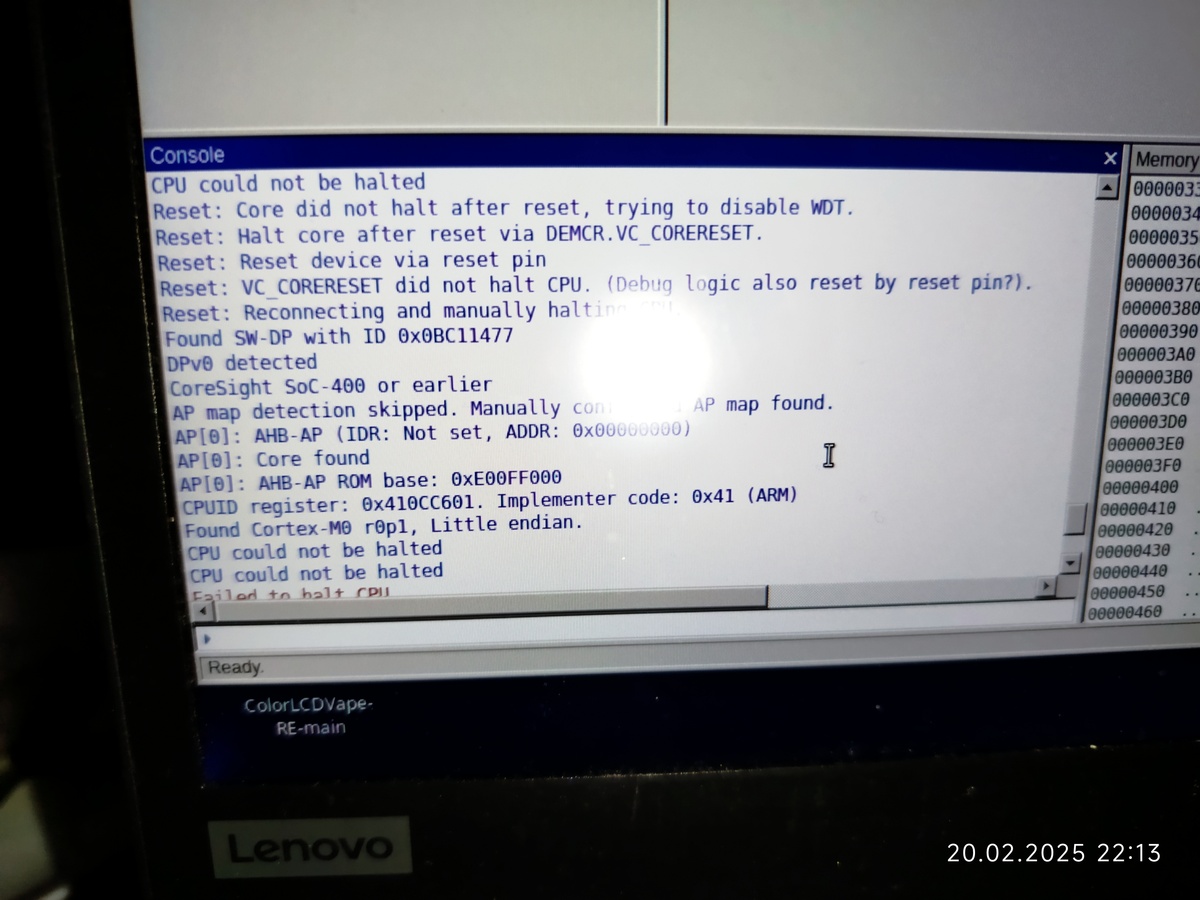
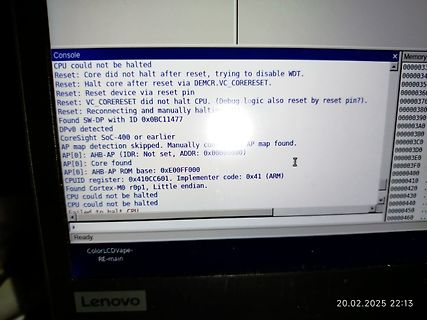
AP map found.
AP[0]: AHB-AP (IDR: Not set, ADDR: 0x00000000)
AP[0]: Core found
AP[0]: AHB-AP ROM base: 0xE00FF000
CPUID register: 0x410CC601. Implementer code: 0x41 (ARM)
Found Cortex-M0 r0p1, Little endian.
CPU could not be halted
CPU could not be halted
Failed to halt CPU
Ready.
Memory
0000033
0000034
BOOT0 auf HIGH gesetzt werden. (Kap. 3.5. in https://download.py32.org/ReferenceManual/en/PY32F030%20Reference%20manual%20v1.3_EN.pdf) Ebenfalls wichtig: Es sind mehrere USART-Boot-Interfaces möglich. Die RX-Pins der nicht benutzten USARTs dürfen nicht floaten. siehe Kap. 1 von UM1503: https://download.py32.org/Tool/en/PY32_IspTool_V1.0.0/UM1503_PY32IspTool_User%20Manual%20V1.0_EN.pdf ISP-Tool: https://py32.org/tool/PY32_ISP.html
Local Oscillator Jitter 100 Hz – 100 kHz 0.3 º rms Notes: 1) Matched to 75 source 2) Two tones at 20 MHz & 25 MHz each of -40 dBm, LO1 at 130 MHz, LO2 at 145.45 MHz 3) Two tones at 20 MHz & 25 MHz each of -16 dBm, LO1 at 130 MHz, LO2 at 145.45 MHz R3v2.0 Mirics Confidential 6 MSi001 Table 8: VHF Mode
www.olimex.com/Products/IoT/ESP32/ESP32-POE/open-source-hardware + einen 1-Wire Temperatursensor (DS18B20) macht ~20€ mit 3D gedrucktem Gehäuse. Hat vielleicht irgendjemand eine andere Lösung? Egal ob Bastelprojekt oder fertig erhältliches.
Temperatursensor (DS18B20) > > macht ~20€ mit 3D gedrucktem Gehäuse. Bei deinen Anforderungen wird es viel günstiger nicht gehen und mit wesentlich weniger Stromverbrauch auch nicht.
Current (Δi ) Range IND Consider the following example: V OUT = 5 V at 0.4 A V IN10-V minimum up to 20-V maximum The selection guide in Figure 24 shows that for a 0.4-A load current, and an input voltage range between 10 V and 20 V, the inductance region selected by the guide is 330 μH. This value of
1302 G10 1302 G11 1302 G12 LT1302-5 Output Voltage vs MaximumOutput Power* Load Current Boost Mode 5.20 20 5.15 16 ) 5.10 ) ( ( G 5.05 E 12 L W V 5.00 VIN= 4V P T U P 4.95 VIN= 2.2V V = 3V T 8 U IN O O 4.90 4 4.85 4.80 0 0 0.1 0.2 0.3 0.4 0.5 0.6 0.7 0.8 0.9 1.0 0 2 4 6 8 10 LOAD CURRENT (A) INPUT VOLTAGE
zueinander, man muss nur die RTCM Daten von Modul > 1 zu Modul 2 senden, erforderliche Bandbreite 10..20kbit/s. Also hier sind Strecken von 2kilometer bis 10/20 ? Möglich? Gruß
oberen Kurven, 2 cm Achsenskala) bzw. Höhe (untere Kurve, 10 cm Achsenskala). "Abweichung_Lage_ab_11_20.JPG" zeigt nur die Schwankung der Lage ab 11:20 (5 mm Raster), ab diesem Zeitpunkt erhält man sehr stabile Messwerte.
1302 G10 1302 G11 1302 G12 LT1302-5 Output Voltage vs MaximumOutput Power* Load Current Boost Mode 5.20 20 5.15 16 ) 5.10 ) ( ( G 5.05 E 12 L W V 5.00 VIN= 4V P T U P 4.95 VIN= 2.2V V = 3V T 8 U IN O O 4.90 4 4.85 4.80 0 0 0.1 0.2 0.3 0.4 0.5 0.6 0.7 0.8 0.9 1.0 0 2 4 6 8 10 LOAD CURRENT (A) INPUT VOLTAGE
stability with a Bode plot, we take the log of Equation 8–18, and plot the logs (Equations 8–19 and 8–20) in Figure 8–6. Z B 20 LOG |Ab| + 20 LOG |Z| * 20 LOG Z Ť Fǒ1 ) Ǔ Ť (8–19) Z F Z B f + TANGENT *1 (Ab ) (8–20) This enables the designer to add and subtract components of the stability equation graph
nicht > überschritten wird. Bestimmt nicht, bei nur 0,7V sperren die FETs für immer. Erlaubte +/-20V sollten bei +12V ja bequem reichen. In stark gestörter Umgebung kann man aber 2 Transzorbs (SMBJ12A) zu R4, R5 parallel schalten.
Peter D. schrieb im Beitrag #7824687: > Erlaubte +/-20V sollten bei +12V ja bequem reichen. Das stimmt natürlich. Trotzdem lasse ich die Transistorlösung noch nicht fallen. Christian M. schrieb im Beitrag #7824776: > Nächste Version... Wenn man
LCCC FK 20 55 Non-RoHS SNPB N / A for Pkg Type -55 to 125 UC1903L & Green Samples UC1903L883B ACTIVE LCCC FK 20 55 Non-RoHS SNPB N / A for Pkg Type -55 to 125 5962- Samples & Green 88697012A UC1903L/ 883B UC3903DW
protection anti collission device 02 798 03 18 0 1 le système anti-collision Umgebungstemperatur: -20°C bis +40°C Funkempfänger ambient temperature: radio receiver 02 798 10 19 0 1 température ambiante: récepteur radio Steuergerät Typ DST 02 798 07 11 0 1 control pendant type DST unité de contrôle type
1.3.5 TSSOP20/SOP20 MC51F7424A1Y/A1M P2.7 1 20 P2.6 VDD 2 19 P2.5 GND 3 18 P2.4/[DIO1] (nRST)/P3.2 4 S 17 P2.3/[CLK1] A O S [CLK0]/P3.3 5 Y 2 n 16 P2.2 A / M [DIO0]/VREF/P3.4 6 M O U 15 P2.1 2 P3.5 7 0 14 P2.0 P0.1
verspricht man in Künzelsau dann folgendes: [c] Thanks to their enlarged solder pads and thicker base plate, the capacitors can withstand acceleration up to 30 g (294 m/s²). . . . The capacitors are tested under conditions that go beyond the requirements of IEC 60384-4: The components must remain
Zeitpunkt der Drucklegung gibt es noch keine Informationen darüber, „welches“ Programm man zur Feier des 20-jährigen Geburtstags plant. Wie immer dürfte allerdings von der Vorstellung von neuen Produkten sowie Vorträgen zur Nutzung der diversen Arduino-Angebote auszugehen sein. ### Arduino, zur Zweiten

 Bild
 Bild
 Bild
 Bild