device. The EMXO offers low-phase noise at 10 Hz < -120 dBc/Hz and Allan Deviation (ADEV) stability <1E-11 at a 1-second averaging time. The atomic clock provides initial accuracy of ±0.5 ppb, low frequency drift performance of <0.9 ppb/mo, and maximum temperature-induced errors of < ±0.3ppb. Together,
Vector Processor (MVP) AI/ML accelerator. With the embedded MVP accelerator, the BG24L provides up to 8x faster inferencing performance using only 1/6th of the power compared to performing the same calculations on the Cortex M, thereby extending battery lif [/c] Mit dem BG22L plant man derweil, einen
eigentlich? Laut Github sollte ja eigentlich "A script named avrdude-gui is installed into the same location as the AVRDUDE CLI program." sein.. Das konnte ich aber bei "avrdude-v8.0-windows-x64.zip" z.B. nicht finden.
Leider bekomme ich keine Daten über den RX Pin. Zum Testen verwende ich ein GPS-Modul, welches 3,3V serielle Daten mit 9600bps ausgibt. Ich habe den Beispielsketch "TFT_Terminal" von der TFT_eSPI lib geflasht (Code ist am Ende des Posts). Der Sketch funktioniert einwandfrei mit den Pins 22 und
board GND Connect RX line to TX line of target board Make sure the target and terminal have the same baud rate and serial settings! The sketch works with the ILI9341 TFT 240x320 display and the called up libraries. The sketch uses the hardware scrolling feature of the display.
CWG input signal can be replicated on any of the CWG output. More information about CWG and FIGURE 3-2: CWG LOW AND HIGH SIDE MODULATIONn the “Motor Commutation” chapter. Figure 3-2 shows the implementation of low and high side modulation on driving a single-phase BLDC motor using CWG. Figure 3-2. CWG
konnte die Bedingung "Gewerbe" nicht entdecken bei 1nce. Hab ich > vielleicht übersehen. AGB 1.3, FAQ, Preise netto Sam schrieb im Beitrag #8047606: > Ich suche eine LTE-M Sim für > ein tracker Projekt, als Privatperson ohne Gewerbeschein, ist es ein > Alptraum eine IoT-Sim zu bekommen.
Sam schrieb im Beitrag #8049131: > aber dass könnte man ja auch für LTE-M/NB-IoT machen, halt ungemein > teurer Also genau das was thingsmobile macht? Sam schrieb im Beitrag #8049131: > Natürlich
Researcher ,ZIMPERIUM • 2010-2015 Self-Employed,custom IT solutions - RE & Research as a hobby - 2013 evad3rs - 2012 Jailbreak DreamTeam - 2011 Chronic-DevT eam Why this topic? • Started to work ~6 months ago at Corellium, virtualizing iPhones (amazing stuff!) • W e have lots of work to focus on,no time to
8 leads; body width 3.9 mm SOT96-1 D E A X c y HE v M A Z 8 5 Q A 2 A (A3) A 1 pin 1 index Lp 1 4 L e w M detail X b p 0 2.5 5 mm scale DIMENSIONS (inch dimensions are derived from the original mm dimensions
externen Frequenzzähler- TOELLNER Electronic Instrumente GmbH 13 Stabilität 1.4 Technische Daten −8 Die im folgenden aufgeführten Spezifikationen bezie- 5x−3 /K und 2 ppm/Jahr −3 PLL-Betrieb; 10 /K−3is 1 MHz, 3x10 /K oberhalb 1 MHz und hen sich auf einen mit 50- -Ausgangslast abgeschlosse- 5x10 /8
OUT A 1 8 V+ –IN A 2 7 OUT B –IN A 2 7 OUT B A A +IN A 3 B 6 –IN B +IN A 3 B 6 –IN B V – 4 5 +IN B V– 4 5 +IN B N8 PACKAGE S8 PACKAGE 8-LEAD PDIP 8-LEAD PLASTIC SO T = 150°C, θ = 130°C/W TJMAX = 150°C,JA = 190
I(fw ) + N c( w ) ▯ 1 ▯ The term I(fw)+ Nc(fw) will be expanded using Taylor’s series expansion, i.e., for any f( x+ h), the Taylor’s series expansion about ‘h’ is given by 0 h2 00 h 3 000 f(x + h) = f(x ) + hf (x) + 2! f (x ) + 3!f (x) + .... ▯ 1 ▯ ▯ 1 ▯ Using first-order Taylor’s expansion for I(fw
12V) diode protector provided Frequency: 50 cps R relay contact 1,000 m V , , 16 24 V DC c g L1 L2 L3 L4 L5 L6 t l Pick-up voltage i v r u 12 Max. L1~L6: HP2-DC24V × 6 pcs. in parallel t - x , Diode protector provided t100 o Min. c100 o Max. / a C u 8 i 80 k e 60 i Drop-out voltage t Max. P 4 Max. a
schneidet sie (mit der Schere) aus und wiegt das Papier... Aber nehmen wir an, seine aktuellen Daten (1x) und die 2x-Daten wären korrekt, dann kann ich mit Excel Daten für 3x, 4x, etc. ausrechnen und auch die Summe der Tagesdefizite der betrachteten 9 Tage. Ich komme auf: 1x: 5520 GWh. 2x: 2880 GWh.
* Use 4-byte instructions here. 1 instruction = 1 entry of the table. * The CPU jumps to MTVEC (i.e. the first entry) in case of an exception, * and (MTVEC & 0xfffffffc) + (mcause & 0x7fffffff) * 4, in case of an interrupt. * * Note: for our CPU, we need to place this on a 256-byte boundary, as CPU * only uses the 24 MSBs of the MTVEC, i.e. (MTVEC & 0xffffff00). */ .balign 0x100 /* Since each entry must take 4-byte, let's temporarily disable the compressed * instruction set that could potentially generate 2-byte instructions. */ .option
selten... Diese integrierten Pegelwandler sind eher für niedrigere Spannungen gedacht, z.B. für 1.8V Flash an einem 3.3V Mikrocontroller.
Maxim B. schrieb im Beitrag #7804724: > Ich habe neulich TXU0304 gekauft: sehr > bequem für SPI, 3x eine Richtung und 1x andere Richtung. Beide > Spannungen können beliebig von 1,1 bis 5,5 Volt gewählt werden. Feste Richtung und Automotive-tauglich. Ich habe TXS0108E im Bastellager, die spielen
is to use a dynamic data type, allocating memory for small blocks of -- RAM data (e.g. a single word) only if they are actually referenced during a -- simulation run. A version of the SRAM model with dynamic memory allocation -- shall be available at the same WWW-site were you obtained
10 T A 25˚C 8 V m e 6 g T = 85C l A V e f 4 O 2 0 0 0.5 1 1.5 2 2.5 3 Common Mode Voltage (V) 78 AT90S2313 0839I–AVR–06/02 AT90S2313 Figure 66. Analog Comparator Input Leakage Current ANALOG COMPARATOR INPUT LEAKAGE
: [https://openwrt.org/toh/tp-link/tl-wr841nd](https://www.google.com/url?sa=E&source=gmail&q=https://openwrt.org/toh/tp-link/tl-wr841nd) * **Achtung:** Stelle sicher, dass du die **korrekte Version** für deinen Router (v8) herunterlädst. Falsche Images können den Router beschädigen
Anfrage an ChatGPT 4o: Der Anfang einer Bilddatei sieht als Hex so aus. Die Bildgröße beträgt 647x421 Pixel. Die Farbtiefe 24 bit. Kannst Du diese Informationen in dem Hexdump finden? 42 4D 2E 7D 0C 00 00 00 00 00 36 00 00 00 28 00 00 00 87 02 00 00 A5 01 00 00 01 00 18 00 00 00 00 00 F8 7C 0C 00
0.45 0.55 c L1 0.60 REF. e e 0.95 BSC. b2 e1 1.90 BSC. θ 0 5 10 θ1 3 5 7 6 8 10 θ1 θ2 2 A A GAUGE PLANE SEATING PLANE 1 θ A L θ2 L1 DETAIL A Dimension (Package B) D e1 DETAIL A Unit : mm b SYMBOL MIN. TYP. MAX. A 1.050 - 1.250 A1 0.000 - 0.100 A2 1.050 - 1.150 b 0.300 - 0.400 c 0.100 - 0.200 1 E D 2.820 - 3.020 E E 1.500 - 1.700 E1 2.650 - 2.950 e 0.950 TYP e1 1.800 - 2.000 c L 0.700REF e L1 0.300 - 0.600 θ 0 - 8 2 A A GAUGE PLANE 0.2 SEATING PLANE 1 θ A L1 L DETAIL A Fortune Semiconductor Corp
RSSGBB7-2K14 PWM2-R1 2 PWM2-G1 2 PWM2-B1 2 PWM2-R2 2 +12V PWM2-G2 2 PWM2-B2 2 R013 22R D001 D002 D003 1 8 2 7 6 6 6 3 6 e e e PWM2-B2 4 5 B B B 5 5 5 R015 560R 4 4 4 1 8 PWM2-R2 e e e 2 7 R R R 3 6 3 3 3 4 5 2 2 2 PWM2-G2 e e e G G G 1 1 1 C008 C009 100N16V NC/100NF 50V P5018/RSSGBB7-2K14 P5018/RSSGBB7-2K14
amplifier so that is CMRR canbe raised to the 80-100dB range. CMRRvs. CommonModeVoltage -4U -50- 0 * x * x 2 + x A I * s Q + * 0 - "n~~~·A U -60- X 0 * * * Chip0 !I G *Chip 1 O O AChip2 -70- XChip3 a) Wr + Chip4 2x * Chip5 0 -80 0 Chip6 -Chip 7 * . XChip8 . on oChip9 *.* .e -vv U -100 - . ..... -110_
110fA2 max tlnA max Non-lnverting Input tlnA max tlOfA max MATING SOCKET vs. Temp (Signal Input Only)t x 2/+7o C vs. SupplyVoltage AC1017 I InputOnly) !2fAlo/o I\PU-I IMPEDANCE [)itferential 3 x lottQll3opF * o.2t6 351 o l4o .(5) TUFLUGS O 1{355) DIA lnvertinglnput (To 4HOTES /INEruONK FEEOAACC'SNX Common
8 leads; body width 3.9 mm SOT96-1 D E A X c y HE v M A Z 8 5 Q A 2 A (A3) A 1 pin 1 index Lp 1 4 L e w M detail X b p 0 2.5 5 mm scale DIMENSIONS (inch dimensions are derived from the original mm dimensions
improved. References 1. “AN-1157 Positive to Negative Buck-Boost Converter SW1 10 V/div) Using LM267X SIMPLE SWITCHER ® Regulators,” Application Report, Texas Instruments, April 2013. 1 Available: www.ti.com/3q14-SNVA022 SW2 10 V/div) Related Web sites www.ti.com/3q14-LM5118 www.ti.com/3q14-LM5022 2 Subscribe to the AAJ: www.ti.com/subscribe-aaj Time 2 µs/div (b.) Buck-boost mode whenIN= 9 V Figure 8. Efficiency with respect to the input voltage 100 95 OUT =3 A 90 85 % ( 80 c i 75 i f 70 E 65 60 55 50 8 12 16 20 24 28 32 36 40 44 48 52 56 60 Input Voltage V) Texas Instruments 25 AAJ 3Q 2014 Analog
For space critical applications, the QFN package would be the suggested package. MCP44X1 TABLE 8-2: PACKAGE FOOTPRINT (1) MCP46X1 Package Package Footprint Dimensions 2 e (mm) m A n d ( e P Type C a t X Y r l A R Rheostat Devices MSOP MS 3.00 4.90 14.70 1.63 MCP46X2 8 MCP44X2 DFN (3x3)
:AIP31068L-AX-BJ-153EN N = “Low”: 1-line display mode F = “Low”: 5 X 8 font type (3) Control Display ON/OFF instruction: D = “Low”: Display OFF C = “Low”: Cursor OFF B = “Low”: Blink OFF (4) Set Entry Mode instruction: I/D = “High”: Increment by 1 SH = “Low”: No entire
o V x x x x x x x x 1 s s . n n n n n n d c v . e e e e e e e e I 3 t t t t t t P 3 P e e e e e e V e e m 8 c a m 8 1 n x x x x x x x x l - - dn 0 D n x x l 0 D 2 e T T T T T T T T c 2 2 s 3 G e T T c 3 G
screen, and main menu screen: N P 6 1 4 0 5 S N : 6 1 4 0 5 1 9 2 . 1 6 8 . 1 2 7 . 2 5 4 H M A I N M E N U S E R V E R S E T T I N G ↓ In addition, you only need to remember to: • Use theSEL button to move up one level (i.e., left to right on the tree graph) • Use theMENU
plant nun, ein Funkmodul für diesen Funkstandard ins Rennen zu schicken. 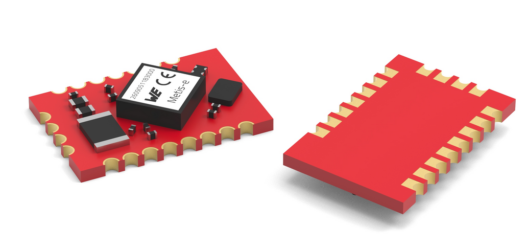 Bildquelle: https://www.we-online.com/en/components/products/METIS-E Die offizielle Ankündigung des Moduls verspricht folgende Spezifikationen: [c] Metis-e is based on the SoC CC1310 chipset
radio module from Würth Elektronik has a range up to 1500 meters and, with dimensions of just 12 × 8 × 2 mm3, is more than 50 percent smaller than comparable models on the market. Metis-e is optimized for automatic meter reading and for use in battery-powered devices. [/c] ### Murata LBWA0ZZ2HK
0x01 0xA0 C 0x01 0x20 0x01 D 0x20 0x97 0x20 E 0x97 0x17 0x97 F 0x17 0xAD 0x17 H 0xAD 0xA9 0xAD I 0xA9 0x29 0xA9 J 0x29 0x2D 0x29 K 0x2D 0x82 0x2D 8.3.2 Keypad Lock/Unlock This user can lock the keypad through
TX EVM 11% Antenna PCB antenna CPU 32-bit RISC CPU Interface UART/GPIO/PWM Working voltage 2.5V ~ 3.6V 3.5mA @RF only Hardware Working current 17mA @TX 10dBm 45mA @TX 14dBm Working temperature -30C ~105° C Storage temperature -45C ~ 135°C Shape 15mm x 17.3mm x 3mm Encryption type AES 128/192/256 Software
PANEL qd back panel (DE4)(Canadian) back panel (DE5)(AEP, UK) 0 screw (BVTP3 x 8) 9 screw (BVTP3 x 8) 8 two screws (BVTP3 x 8) 3 CNP901 7 two screws (BVTP3 x 8) qa screw (BVTP3 x 8) 5 two screws (BVTP3 x 8) 2 CNS8 6 five screws (BVTP3 x 8) qs screw (BVTP3 x 8) 1 CNS7 4 CNP154
are used to encrypt further data exchanged between the client and server. ETSI 10 ETSI TS 103 523-3 V1.1.1 (2018-10) 4.3.2 eTLS Diffie-Hellman key exchange The eTLS key exchange shall use exactly the same messages and procedures to establish a set of session keys as a TLS 1.3 ephemeral Diffie-Hellman
Circuit by Constant Current, Output Tracking Over Voltage, Over Protections Temperature Special Features 3 User defined VI preset, Remote control V, I and output on-off, Remote Sensing (for HCS- 3600 only) Approvals CE EMC: EN 55011, 55022 LVD: EN 60950, 61010 Dimensions (WxHxD) 200 x 90 x 275 mm 7.9 x 3.5 x 10.8 inch Weight 3.2 kg 7 lbs 12. PC Interface Control Support OS: Windows XP/Vista/7 (32bits/64bits) Driver: Silicon Lab CP210x USB driver (Included in CDROM folder “USB CP210x Drivers V6.6.1 for Win_XP_S2K3
*GENERAL HELP ABOUT THIS VERSION (V3.30) ... Below lists the changes made on Version 3.30. - Fixed Translator 16V8-to-18CV8 bug. - Fixed Translator EP320-to-18CV8 bug. ABOUT THIS VERSION (V3.20) ... Below lists the feature added on Version
stabil gelaufen. Vielleicht sind die neuen "TRETAKT" und "INSPELNING" ja besser, sind aber mit 8 und 10 Eur auch am unteren Ende der Preisskala angesiedelt.
of enable voltage; typical values aaa-029400 aaa-029445 0.3 0.4 out Iout (A) (A) (1) (2) 0.3 (1) 0.2 (2) 0.2 (3) 0.1 (4) 0.1 (5) 0 (6) 0 0 4 8 12 1 10 102 V (V) R out ext V = 3.3 V; T = 25 °C V = 3.3 V; T = 25 °C EN amb EN amb (1) R ext= 3 Ω (1) Vout= 1.4 V (
