-
PDF
BK2433Datasheetv1.0.pdf
_0 Please write with 0 x08B2 --2401table_A) 0xFFFFFEF7CF208104082041 0 x08B1 0 x08B0 0 x08AF 0 x08AE 0 x08AD 0 x08AC 0 x08AB 0 x08AA 0 x08B5 BK2423_ce 7:1 reserved 0 ce 8'b10000000 : Flush RX 8'b10100000 : Flush TX 8'b00010000
in „Chinesische USB/nRF24L01 Adpapter“ · Mikrocontroller und Digitale Elektronik ·
-
PDF
7inch-Capacitive-Touch-LCD-Schematic.pdf
R R R R R R R R J7 L_G6 19 G5 L_G0 27 R7 27 26 RX7 I2C_SCL1 6 L_G7 20 G6 42 L_G1 26 G0 26 25 RX6 9 8 7 6 5 4 3 2 1 9 I2C_SDA1 4 PAD L_B0 21 G7GND L_G2 25 G1 25 24 RX5 U7 3 3 3 3 3 3 3 3 3 2 CAP_WAKE 3 L_B1 22 B0 L_G3 24 G2 24 23 RX4 CAP_INT 2 5 下接 L_B2 23 B1 L_G4 23 G3 23 1 X X X X X X X X X 1 PAD B2 G4 B 22 22 RX3 X R R R R R R R R R INT 28 CAP_INT J8 L_B3 24 B3 L_G5 22 G5 B 21 21 RX2 1 NC R WAKEUP 27 1 CON4 L_B4 25 B4 L_G6 21 G6 20 20 RX1 TX15 2 TX15
in „TFT LED Backlight PWM“ · Mikrocontroller und Digitale Elektronik ·
-
PDF
7inch-Capacitive-Touch-LCD-Schematic.pdf
R R R R R R R R J7 L_G6 19 G5 L_G0 27 R7 27 26 RX7 I2C_SCL1 6 L_G7 20 G6 42 L_G1 26 G0 26 25 RX6 9 8 7 6 5 4 3 2 1 9 I2C_SDA1 4 PAD L_B0 21 G7GND L_G2 25 G1 25 24 RX5 U7 3 3 3 3 3 3 3 3 3 2 CAP_WAKE 3 L_B1 22 B0 L_G3 24 G2 24 23 RX4 CAP_INT 2 5 下接 L_B2 23 B1 L_G4 23 G3 23 1 X X X X X X X X X 1 PAD B2 G4 B 22 22 RX3 X R R R R R R R R R INT 28 CAP_INT J8 L_B3 24 B3 L_G5 22 G5 B 21 21 RX2 1 NC R WAKEUP 27 1 CON4 L_B4 25 B4 L_G6 21 G6 20 20 RX1 TX15 2 TX15
in „STM32F4 I2C ACK bei 1.5V“ · Mikrocontroller und Digitale Elektronik ·
-
Datei
extrx.c
extRxReceiveSBusFrame(); if(SBUS_Flags.New_Frame_received==1){ extRxDecodeSBusChannels(); } #else extRxDecodeCppm(); #endif } } static void extRxDecodeChannels(void) { commanderPacket.thrust = cppmConvert2uint16
in „FreeROTS Fehler "AssertFail" durch Befehl xQueueReceive“ · Mikrocontroller und Digitale Elektronik ·
-
PDF
2025-01-18_SPI_as_1Wire.pdf
t v[2]; struct __attribute__((packed)) { uint8_t LB; uint8_t HB; } byte; struct __attribute__((packed)) { uint8_t b0 : 1; uint8_t b1 : 1; uint8_t b2 : 1; uint8_t b3 : 1; uint8_t b4 : 1; uint8_t b5 : 1; uint8
in „1-Wire-Bus mit SPI-Modul des PIC“ · Mikrocontroller und Digitale Elektronik ·
-
PDF
SAM7-EX256_Rev_C-sch.pdf
B4 R37 R83 3.3K RX3 2K R D N N D T T N R E LED100/DUP KY AY YELLOW 4 C<3> D<6> 330 PA3/RTS0 R84 3.3K RX2 MDIO 1 D G G V G D R 36 7 KY 1:1 75 75 J 3 R85 3.3K RX1 MDC 2 MDIO V V GND5 35 R77 NA 6 RD+ R 7
in „SPI-Initialisierung von zwei Geräte über den gleichen Bus“ · Mikrocontroller und Digitale Elektronik ·
-
Datei
RFM70_init.c
,0xF7,0xFE,0xFF,0xFF }; //Bank0 register initialization value const UINT8 Bank0_Reg[][2]={ {0,0x0F},//reflect RX_DR\TX_DS\MAX_RT,Enable CRC ,2byte,POWER UP,PRX {1,0x3F},//Enable auto acknowledgement data pipe5\4\3\2\1\0 {2,0x3F},//Enable RX Addresses pipe5\4\3\2\1\0 {3,0x03},//RX/TX address
in „Hat jemand Erfahrung mit dem 2,4GHz-Transceiver RFM70?“ · HF, Funk und Felder ·
-
PDF
MT6223C.pdf
by setting “2’b10” for BLPEN(Baseband Loopback Enable) or “bypass-Filter Loopback Mode” by setting “ 2’b01” for BLPEN in RX_CON control register. 5.2.7 Register Definitions 5.2.7.1 APB Register BFE +0010h RX Configuration
in „GSM-Modul (SIM908) nur analoge Ausgänge für Anruf?“ · HF, Funk und Felder ·
-
PDF
Akkulader_Beschreibung.pdf
; Z (R31:R30) für verschiedene Zwecke außerhalb von Interrupts ; ; BitDefinitionen für rFlg .EQU bUartRxLine = 7 ; Eine vollständige Zeile über UART empfangen .EQU bLcdOk = 6 ; LCDAnzeige angeschlossen und ok ; nicht benutzt: Bits 3, 4 und 5 .EQU bMin = 2 ; Timer hat 1 Minute erreicht .EQU b32m =
in „2A 1s Li-ion Lader + Protection“ · Analoge Elektronik und Schaltungstechnik ·
-
Datei
ethernet.c
HEADER; // header uint8_t* DATA_BUFFER_ADDRESS; // data buffer address ETH_Buffer_Offset_8 STAT; // TX/RX packet status uint32_t RSV; uint32_t* NEXT_ED; // next descriptor (hdr.NPV==1); } ETH_Buffer; // hardware TX/RX descriptor (linked). uint8_t RX_Data_Buffer[2][1536]; ETH_Buffer RX_Header[2]; uint8_t TX_Data_Buffer[2][1536]; ETH_Buffer TX_Header[2]; void ethernet_init(){ RX_Header[0].HEADER.EOWN = 1; RX_Header[0].HEADER.NPV = 1; RX_Header[0].DATA_BUFFER_ADDRESS = &RX_Data_Buffer[0][0]; RX_Header[0].NEXT_ED = (uint32
in „Pic32MX - Ethernet - Einstellung“ · Mikrocontroller und Digitale Elektronik ·
-
Datei
boarddemo.v
*******************************// wire clknub; wire locked; wire reset; DCM_SP #( .CLKIN_DIVIDE_BY_2("TRUE"), .CLKIN_PERIOD(20.000)) DCM_SP_INST ( .CLKIN(CLK_50M), .CLKFB(clk), .RST(1'b0), .PSEN(1'b0), .PSINCDEC(1'b0), .PSCLK(1'b0), .DSSEN(1'b0), .CLK0(clknub), .CLK90(), .CLK180(), .CLK270(), .CLKDV
-
Datei
test.c
O MOSI B6 I MISO B7 O SCK C0 ? C1 ? C2 - (JTAG) C3 - (JTAG) C4 - (JTAG) C5 - (JTAG) C6 ? C7 ? D0 I Up D1 - (Debug TX) - aendert sich nach power-up irgendwie... D2 I GDO0 D3 I GDO2 (packet rx) D4 O Relay D5 -
in „Alternative Firmware für Homematic Komponenten“ · Haus & Smart Home ·
-
PDF
flash.pdf
17 18 #COM_RTS 1 2 PB14 $COM_RX $USB_RX $I2C_SCL #COM_RX #COM_TX 3 4 PD7 19 20 #USB_RX PB13 PB12 PB11 5 6 PB10 #COM_CTS #USB_CTS 7 1 8 1 1 1#PG0 PE15 9 2 10 PE14 PE13 0 PE12 2 M 2 B 0 PE11 11 N 12 PE10 COM_CTS O USB_CTS
-
PDF
VAR-6ULCustomBoard-Datasheet.pdf
3 UART3_RTS_B IO UART3 RTS 4 GPIO1_1 IO GPIO1[1] 5 UART3_RX IO UART3 RX 6 GPIO1_2 IO GPIO1[2] 7 UART3_TX IO UART3 TX 8 MICBIAS P MicrophoneBias 9 LCD_DATA20 IO LCD Data bit 20 10 MICIN AI AnalogMicrophoneIn Table
in „[V] Variscite DART-6UL Development Kit inkl. 7" LCD NXP iMX6UL“ · Markt ·
-
Datei
uart.txt
ina90.h> #include <avr/interrupt.h> #include <avr/signal.h> /* UART Buffer Defines */ #define USART_RX_BUFFER_SIZE 128 /* 2,4,8,16,32,64,128 or 256 bytes */ #define USART_TX_BUFFER_SIZE 128 /* 2,4,8,16,32,64,128 or 256 bytes */ #define USART_RX_BUFFER_MASK ( USART_RX_BUFFER_SIZE - 1 ) #define USART_TX_BUFFER_MASK ( USART_TX_BUFFER_SIZE - 1 ) #if ( USART_RX_BUFFER_SIZE & USART_RX_BUFFER_MASK ) #error RX buffer size is not a power of 2 #endif #if ( USART_TX_BUFFER_SIZE & USART_TX_BUFFER_MASK ) #error TX buffer size is not a power of 2 #endif /* Static Variables
in „SIGNAL mit UART0 und atmega128 funktioniert nicht...“ · Mikrocontroller und Digitale Elektronik ·
-
PDF
notes_82b96.pdf
side, the total 82B96 delay seen on the left hand bus, after release by an I2C chip, will be [delay while left I2C rises from 0V to 0.6V + delay in 82B96 till TxD goes high + delay in P82B96 after RxD goes high until I2C
in „18 x SHT11 an welchem Mikrocontroller“ · Mikrocontroller und Digitale Elektronik ·
-
PDF
notes_82b96.pdf
side, the total 82B96 delay seen on the left hand bus, after release by an I2C chip, will be [delay while left I2C rises from 0V to 0.6V + delay in 82B96 till TxD goes high + delay in P82B96 after RxD goes high until I2C
in „I²C galvanisch trennen“ · Mikrocontroller und Digitale Elektronik ·
-
Datei
mac.c
*********************************************************/ #pragma data_alignment = 4 static tByte bRxBuffer[MAC_RX_FRAGMENTS * ETH_FRAG_SIZE]; #pragma data_alignment = 4 static tByte bTxBuffer[MAC_TX_FRAGMENTS * ETH_FRAG_SIZE]; /**********************************************************************
in „IP-Stack bauen“ · Mikrocontroller und Digitale Elektronik ·
-
PDF
NRF_Modul.pdf
switch (u8Pipe) { case 0x0A: u8PipeReg = RX_ADDR_P0; break; case 0x0B: u8PipeReg = RX_ADDR_P1; break; case 0x0C: u8PipeReg = RX_ADDR_P2; break; case 0x0D: u8PipeReg = RX_ADDR_P3; break; case 0x0E: u8PipeReg = RX_ADDR_P4; break; case 0x0F: u8PipeReg
in „ATmega 164P USART funktioniert nur mit beschaltung auf PB7“ · Mikrocontroller und Digitale Elektronik ·
-
PDF
AiMS2000.pdf
TRST_N P1.0/5.1B 95 P1.0/ENET-TXD0 P0.0/CAN_RX1/TXD3/SDA1 46 SDA1/2.3B 2 TDI P1.1/5.1B 94 P1.1/ENET-TXD1 P0.1/CAN_TX1/RXD3/SCL1 47 SCL1/2.4B 3 TMS/SWDIO P1.4/5.2B 93 P1.4/ENET-TX_EN P0.2/TXD0/AD0.7 98 TX0/5.1A 5 TCK/SWDCLK P1.8/5.2B 92 P1.8/ENET_CRS P0.3/RXD0/AD0.6 99 RX0/5.1A 101 RTCK P1.9/5.2B 90 P1.9/ENET_RXD0 P0.4/I2SRX_CLK/CAN_RX2/CAP2.0 80 CAN2_IN/4.4C . 17 TDO/SWO P1.10/5.2B 89 P1.10/ENET_RXD1 P0.5/I2SRX_WS/CAN_TX2/CAP2.1
in „Schaltplan Prüfung/Kritik LPC1769 + IMU + Bluetooth“ · Mikrocontroller und Digitale Elektronik ·
-
PDF
AiMS2000.pdf
/2.4B 3 TMS/SWDIO P1.4/5.2B 93 P1.4/ENET-TX_EN P0.2/TXD0/AD0.7 98 TX0/5.1A TCK/SWDCLK 5 TCK/SWDCLK P1.8/5.2B 92 P1.8/ENET_CRS P0.3/RXD0/AD0.6 99 RX0/5.1A 101 RTCK P1.9/5.2B 90 P1.9/ENET_RXD0 P0.4/I2SRX_CLK/CAN_RX2/CAP2.0 80 CAN2_IN/4.4C TDO/SWO 17 TDO/SWO P1.10/5.2B 89 P1.10/ENET_RXD1 P0.5/I2SRX_WS/CAN_TX2/CAP2.1 79 CAN2_OUT/4.4C 14 NRESET P1.14/5.2B 88 P1.14/ENET-RX_ER P0.6/I2SRX_SDA/SSEL1/MAT2.0 78 NRESET RSTOUTN
in „Schaltplan Prüfung/Kritik LPC1769 + IMU + Bluetooth“ · Mikrocontroller und Digitale Elektronik ·
-
Datei
USARThandle.inc
, SREG ; save register push temp1 push temp2 in temp1,UDR lds temp2, UART_Buffer_Result ; check if new data ready can to receive? tst temp2 brne _Rx_ret1 lds temp2, UART_Buffer_Count tst temp2 brne _Rx_get ldi YH,high (UART_RX_Buffer) ; load pointer
-
Datei
nrf24l01.c
Empfangener Datensatz typedef struct { uint16_t id; uint16_t nr; float temperatur_1; float temperatur_2; float feuchte; float ubatt; } __attribute__((packed)) rf_data_t; /* Extrahierter Inhalt des Status Registers */ typedef struct { _Bool rx_dr, // Data Ready RX Fifo Interrupt tx_ds, // Data Sent FIFO
in „NRF24L01: Handauflegen hilft?“ · Mikrocontroller und Digitale Elektronik ·
-
Datei
main.c
PD3 // Pins #define PORT_LED PORTB #define PIN_LED 0x01 // PB0 // States #define STOP 0 #define REC 2 // MMC #define START_SECTOR 528 // This is the sector number where the search for midi files begins (no FAT32 readings!) #define TX_BUF_SIZE 128 #define RX_BUF_SIZE 128 // Variables u08 sharedmem[512
in „NMEA wird nicht richtig empfangen (SkyTraq 6 ST22, ATmega8L)“ · Mikrocontroller und Digitale Elektronik ·
-
Datei
rf_defines.h
REG_OBSERVE_TX 0x08 //Transmit observe register #define NRF24L01_REG_RPD 0x09 #define NRF24L01_REG_RX_ADDR_P0 0x0A //Receive address data pipe 0. 5 Bytes maximum length. #define NRF24L01_REG_RX_ADDR_P1 0x0B //Receive address data pipe 1. 5 Bytes maximum length. #define NRF24L01_REG_RX_ADDR_P2 0x0C //
in „[STM32F4xx] NRF24L01+ Funkmodul Source Code“ · Projekte & Code ·
-
PDF
dm9000b_dm9010b_layoutguide.pdf
• Traces routed from the DM9000B / 9010B RX± pair to the 10/100M magnetic and the RJ45 connector should run symmetrically, directly, identically, and closely (no more than 2mm). The same rule is applied to tracesroutedfromtheDM9000B
in „Interesse an einfach erweiterbarem Experimentierboard fuer den Xmega128a1?“ · Mikrocontroller und Digitale Elektronik ·
-
Datei
radio.c
address for pipe 3 is 0xc2c2c2c2c4 (disabled) // default address for pipe 4 is 0xc2c2c2c2c5 (disabled) // default address for pipe 5 is 0xc2c2c2c2c6 (disabled) void Radio_Configure_Rx(RADIO_PIPE pipe, uint8_t* address, uint8_t
in „NRF24L01 scheint nicht zu senden (MAX_RT)“ · Mikrocontroller und Digitale Elektronik ·
-
PDF
UM3758-120A.pdf
LTD. IN TAIWAN R.O.C. ,- ._. 11 UM3758 Series ApplicationCircuits(Continued) (B) Use Normal Two-Contact Pushbutton (6) - 1 Appiication Circuit with Data Bit High to Low - U 24 DD L1 ? - = v - + w 21 ODE 1OOKn. IOOKn 19 sc 0 c 120 PF ; L - - - - L2 17 23 X/RX OUT 22 < U M 37 58 408 A < 21 18 08 m 18 /B /A M /BM 20 23 TX/RX OUT : m _ i ! i OPERFITION : D i.02, . . . ..D8QRE NOR,,F\LHIGH. PND DI FQLLS LON UHILE SN1 1s DEPRESSED; DZ, 0 3 ...0 UILL 5 QCT AS 01. i (B) - 2 Application Circuit with Data Bit
in „Funksteuerung/Fernsteuerung Bitte um Hilfe“ · HF, Funk und Felder ·
-
Datei
uart.c
interrupt handling routines use circular buffers for buffering received and transmitted data. The UART_RX_BUFFER_SIZE and UART_TX_BUFFER_SIZE variables define the buffer size in bytes. Note that these variables must be a power of 2. USAGE: Refere to the header file uart.h for a description of the routines
in „UART im AVR Studio simulieren“ · Mikrocontroller und Digitale Elektronik ·
-
 Bild
Bild
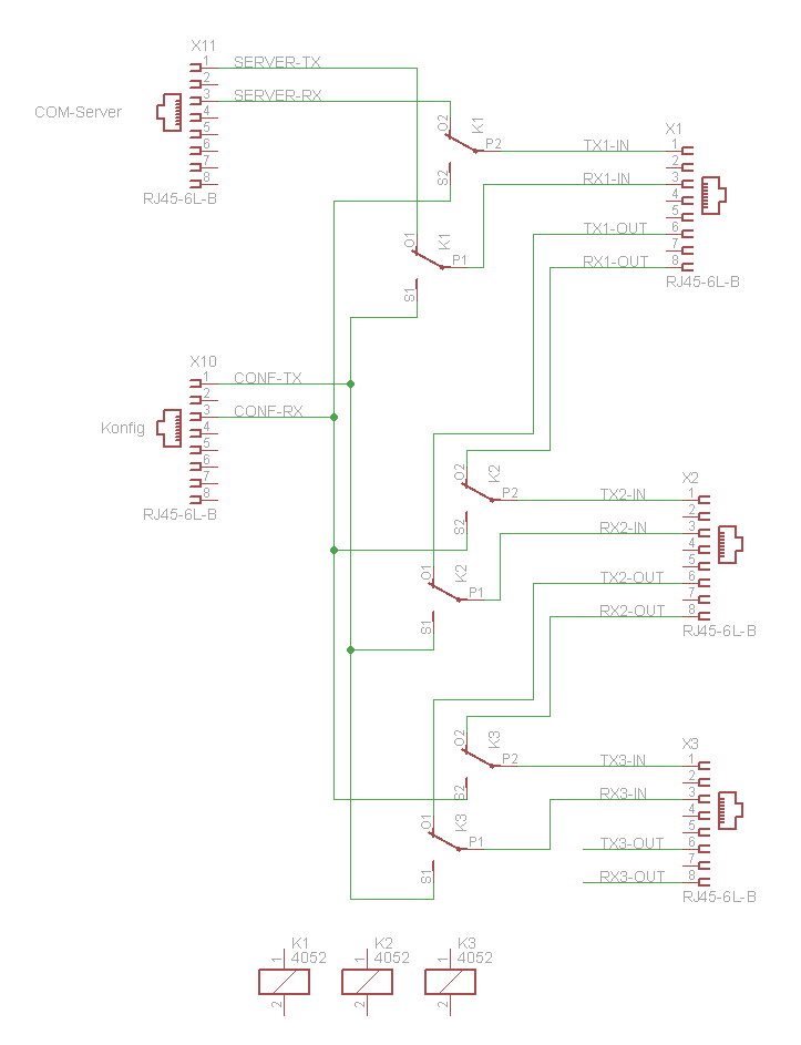
Schaltplan mit RJ45-Steckern und Schaltern
X11 SERVER-TX SERVER-RX RJ45-6L-B X10 CONF-TX CONF-RX RJ45-6L-B K1 P2 TX1-IN 1 2 3 4 5 6 7 8 P1 TX1-OUT RX1-OUT RJ45-6L-B S1 S2 O1 K1 O2 K2 P2 TX2-IN 1 2 3 4 5 6 7 8 RX2-IN X2 RX2-OUT TX2-OUT RJ45-6L-B S1 S2 O1 K2 P1 TX2-OUT RX2-OUT K3 P2 TX3-IN 1 2 3 4 5 6 7 8 RX3-IN X3 TX3-OUT RX3-OUT RJ45-6L-B S1 S2 O1 K3 P1 TX3-OUT RX3-OUT K1 4052 K2 4052 K3 4052
in „9x RS232 anbinden / Denkanstoß zur Entwicklung eines RS232 digitalen Umschaltt. Hilfe benötigt“ · Mikrocontroller und Digitale Elektronik · · Schaltpläne
-
PDF
final_board.pdf
5 TCK/SWDCLK P1.8/5.2B 92 P1.8/ENET_CRS P0.3/RXD0/AD0.6 99 RX0/5.1A 100 RTCK P1.9/5.2B 91 P1.9/ENET_RXD0 P0.4/I2SRX_CLK/CAN_RX2/CAP2.0 81 CAN2_IN/4.4C 1 TDO/SWO P1.10/5.2B 90 P1.10/ENET_RXD1 P0.5/I2SRX_WS/CAN_TX2/CAP2.1 80 CAN2_OUT/4.4C 17 NRESET P1.14/5.2B 89 P1.14/ENET-RX_ER P0.6/I2SRX_SDA/SSEL1/MAT2.0 79 14 RSTOUTN 88 P1.15/ENET-RX_CLK P0.7/I2STX_CLK/SCK1/MAT2.1 78 P0.7/5.1B B 3 . 3 V L1 - Coilcraft 0603PS-103KLB 87 P1.16
in „Schaltplan Prüfung/Kritik LPC1769 + IMU + Bluetooth“ · Mikrocontroller und Digitale Elektronik ·
-
PDF
RF12B-IC-2.pdf
, bit 1 should be cleared and set. 8. Synchron pattern Command bit 15 14 13 12 11 10 9 8 7 6 5 4 3 2 1 0 POR 1 1 0 0 1 1 1 0 b7 b6 b5 b4 b3 b2 b1 b0 CED4h The Byte0 used for synchron pattern detection can be reprogrammed by B <b7:b0>. 9.Receiver FIFO Read Command bit 15 14 13 12 11 10 9 8 7 6 5 4 3
in „Funk SI4420 kein Empfang“ · Mikrocontroller und Digitale Elektronik ·
-
Datei
Daterf.c
initat() { // Input/Output Ports initialization // Port A initialization // Func0=In Func1=In Func2=In Func3=In Func4=In Func5=In Func6=In Func7=In // State0=T State1=T State2=T State3=T State4=T State5=T State6=T State7=T PORTA=0x00; DDRA=0x00; // Port B initialization // Func0=In Func1=In Func2=In
in „Problem mit CodevisionAVR 1.23.8c Standard“ · Mikrocontroller und Digitale Elektronik ·
-
PDF
Star10_Part1.pdf
supply out 2 (TX): 13.7 V dc at •SecondIF(9MHz)ultimatebandwidths:32 (AIPA): Programmable –3 dB, –6 dB, 20 A max continuous polecascaded,SSB2.4kHz,1.8kHz;CW, –10 dB steps • Power supply spurious as seen by the re
in „Projekt Kurzwellenempfänger Doppelsuper welcher VCO?“ · HF, Funk und Felder ·
-
Datei
UART.c
initialize UART*/ void inituart() { //Baudrate 19200 (siehe Baudrate Tabelle) für 4MHz tUART_TX = 0; tUART_RX = 1; U2BRG = BAUDRATE; //Global definierte Baudrate wählen //IPC7bits.U2TXIP = 0b0011; //Interrupt Priorität 3 //IPC7bits.U2RXIP = 0b0011; //Interrupt Priorität 3 U2STA = 0; //Control-Register rücksetzen
in „PIC32MX795 und UART4: Kein Interrupt beim Empfang von Zeichen.“ · Mikrocontroller und Digitale Elektronik ·
-
Datei
display.asm
.def RX0 = r16 ; Variablen für Mathe und BIN_to_BCD .def RX1 = r17 ; .def RX2 = r18 ; .def RX3 = r19 ; .def RX4 = r20 ; BCD value digits 0 and 1 .def RX5 = r21 ; BCD value digits 2 and 3 .def RX6 = r22 ; BCD
in „LCD Routine Funktioniert nicht“ · Mikrocontroller und Digitale Elektronik ·
-
Datei
ISR_ROUTINE.c
" und Zähler kleiner 116 Zeichen UART_RX_BUFFER[UART_RX_COUNTER] = DATA; // Daten in Buffer schreiben UART_RX_COUNTER++; // Zähler erhöhen } } } void GET_STRING(char *DATEN) { if(UART_RX_FLAG == 1){ // Empfangsbuffer voll strcpy(DATEN, UART_RX_BUFFER
in „Keine vollst. Übertragung der Strings über UART“ · Mikrocontroller und Digitale Elektronik ·
-
Datei
ISR_ROUTINE.c
" und Zähler kleiner 116 Zeichen UART_RX_BUFFER[UART_RX_COUNTER] = DATA; // Daten in Buffer schreiben UART_RX_COUNTER++; // Zähler erhöhen } } } void GET_STRING(char *DATEN) { if(UART_RX_FLAG == 1){ // Empfangsbuffer voll strcpy(DATEN, UART_RX_BUFFER
in „Keine vollst. Übertragung der Strings über UART“ · Mikrocontroller und Digitale Elektronik ·
-
Datei
CC1000.txt
.include "m8def.inc" .def temp1 = r16 .def CC1000_tx = r17 .def CC1000_rx = r18 .def USART_tx = r19 .def USART_rx = r20 .def CC1000_Address = r21 .def CC1000_Data = r22 .def i1 = r23 .def temp2 = r24 .equ CC1000_DDR = DDRB .equ CC1000_Port = PortB .equ CC1000_PIN = PINB .equ
in „Funkverbindung zwischen AVRs !“ · Mikrocontroller und Digitale Elektronik ·
-
Datei
rfm12.c
will detect that. //end RX and signalize new packet RFM12_trans(0x8208); RFM12_status.Rx = 0; RFM12_status.New = 1; } } else if(RFM12_status.Tx) { //transmit next byte RFM12_trans(0xB800 | RFM12_Data[RFM12_Index]); if(!RFM12_Index
in „RFM12 zuckt nicht ein bisschen.“ · Mikrocontroller und Digitale Elektronik ·
-
Datei
IC_CC1101.cpp
Synthesizer Control halRfWriteReg(BSCFG,0x1C); //Bit Synchronization Configuration halRfWriteReg(FREND1,0xB6); //Front End RX Configuration #else //GDO2 7-nc ; 6-Invert? 5:0-Mode (table41 page62) // SpiWriteReg(IOCFG2, 0x0B); //serial clock.synchronous to the data in synchronous serial mode halRfWriteReg(IOCFG2
in „In-Circuit radino CC1101 Modul Hängt im SPI Transfer“ · Mikrocontroller und Digitale Elektronik ·
-
PDF
AiMS2000.pdf
/ENET-RX_CLK P0.7/I2STX_CLK/SCK1/MAT2.1 . L1 - Coilcraft 0603PS-103KLB 87 77 B D 1 10 86 P1.16/ENET-MDC P0.8/I2STX_WS/MISO1/MAT2.2 76 3 3 X . 12 VREFP 32 P1.18/USB_UP/PWM1.1/CAP1.0 P0.9/P0.10/TXD2/SDA2/MAT3.0
in „Schaltplan Prüfung/Kritik LPC1769 + IMU + Bluetooth“ · Mikrocontroller und Digitale Elektronik ·
-
PDF
Nano-Every-AdapterBoard.pdf
6 D10 2 - U1A 2K2 LED Drill-Hole1 D13 R1 + 1 V D14 7 8 D9 TLV9004 B 4 1K D15 9 10 D8 R28 B LED 2K2 V D11 5 Drill-Hole2 U4 D16 11 12 D7 + R41 D11 2 D17 13 14 D6 1K 7 6 D18 15 16 D5 - U1B 2K2 LED Drill-Hole3 GND
in „Invertierender Impedanzwandler - Rätsel“ · Analoge Elektronik und Schaltungstechnik ·
-
PDF
Nano-DevBoard.pdf
6 D10 2 - U1A 2K2 LED Drill-Hole1 D13 R1 + 1 V D14 7 8 D9 TLV9004 B 4 1K D15 9 10 D8 R28 B LED 2K2 V D11 5 Drill-Hole2 U4 D16 11 12 D7 + R41 D11 2 D17 13 14 D6 1K 7 6 D18 15 16 D5 - U1B 2K2 LED Drill-Hole3 GND
in „OPV Unterschiede Empfindlichkeit?“ · Analoge Elektronik und Schaltungstechnik ·
-
PDF
Nano-Every-AdapterBoard.pdf
GND 14 GND GND 29 GND RX1 2 RX1 RX1 14 RX1 27 28 RX1 RX1 14 1 VIN VIN 29 30 VIN 15 VIN VIN 30 1 TX1 TX1 15 TX1 29 30 TX1 TX1 15 VIN TX1 B +5V B K4 R27 D13 1 2 D12 D12 3 + R40 D12 1 TLV9001 5 R10 3V3 3 4 D11 1K 3 D13 AREF 5 6
-
Datei
UART.c
) ) #else #define INITIAL_TIMER0_SEED ( 256 - (( (SYSTEM_CLOCK / BAUDRATE) / TIMER_PRESCALER ) * 3/2) ) #define USI_COUNTER_SEED_RECEIVE (USI_COUNTER_MAX_COUNT - DATA_BITS) #endif #define UART_RX_BUFFER_MASK ( UART_RX_BUFFER_SIZE - 1 ) #if ( UART_RX_BUFFER_SIZE & UART_RX_BUFFER_MASK ) #error RX buffer
in „Pinchange Interrupt geht nicht ATtiny45“ · Mikrocontroller und Digitale Elektronik ·
-
Datei
SNAP.c
---- void SnapReceiveChar(unsigned char ch) { unsigned int x; static unsigned int crc = 0; if (SnapRxState == SNAP_STATE_HEADER2) crc = crc16(&ch, 1); else if ((SnapRxState > SNAP_STATE_HEADER2) & (SnapRxState <= SNAP_STATE_DATA)) crc = crc16_continue(&ch, 1, crc); switch (SnapRxState) { case SNAP_STATE_PREAMBLE1: { if (ch == SNAP_PREAMBLE1) { SnapRxState++; } }break; case SNAP_STATE_PREAMBLE2: { if (ch == SNAP_PREAMBLE2) { SnapRxState++; } else { SnapRxState=0; } }break; case SNAP_STATE_SYNC: { if (ch == SNAP_SYNC) { SnapRxState++; } else { SnapRxState
in „Immer noch Probleme beim Empfangen“ · Mikrocontroller und Digitale Elektronik ·
-
Datei
USI_UART.c
) ) #else #define INITIAL_TIMER0_SEED ( 256 - (( (SYSTEM_CLOCK / BAUDRATE) / TIMER_PRESCALER ) * 3/2) ) #define USI_COUNTER_SEED_RECEIVE (USI_COUNTER_MAX_COUNT - DATA_BITS) #endif #define UART_RX_BUFFER_MASK ( UART_RX_BUFFER_SIZE - 1 ) #if ( UART_RX_BUFFER_SIZE & UART_RX_BUFFER_MASK ) #error RX buffer
in „IAR vs. GCC“ · Mikrocontroller und Digitale Elektronik ·
-
Datei
i2c.c
i2cTXByteCtr = 0; static char i2cRX = 0; void i2cSetupPins(void) { P1SEL |= BIT6 + BIT7; // Assign I2C pins to USCI_B0 P1SEL2 |= BIT6 + BIT7; // Assign I2C pins to USCI_B0 } void i2cSetupTx(const char address
in „Hilfe beim Auslesen eines Sensors“ · Mikrocontroller und Digitale Elektronik ·
-
Datei
i2c.c
i2cTXByteCtr = 0; static char i2cRX = 0; void i2cSetupPins(void) { P1SEL |= BIT6 + BIT7; // Assign I2C pins to USCI_B0 P1SEL2 |= BIT6 + BIT7; // Assign I2C pins to USCI_B0 } void i2cSetupTx(const char address
in „I2C timing problem“ · Mikrocontroller und Digitale Elektronik ·