Linear Regulator istheswitchedpowersupplyoutput.Witha10mAload,it typically provides a voltage of (V BAT – 0.17V). The whole The LTC1540 can be connected as a micropower (I Q = 5.5µAatV =5V)lowdropoutlinearregulator(Figure7). circuitdrawsamere0.8µAofquiescentcurrentwithV BAT IN =5V.Thethreeresistorvoltagedividerprograms50mVof
for Use in Legal Metrology Contents Page Page General View of the Scale 1– 0 Care and Maintenance 1–42 Cleaning 1–42 Installation Instructions 1– 5 Safety Inspection 1–43 Zone 2/Class I, Division 2 Hazardous Areas/Locations 1– 8 Scale Operating Menu 2– 1 Changing Menu Code Settings 2– 1 Setting Up the
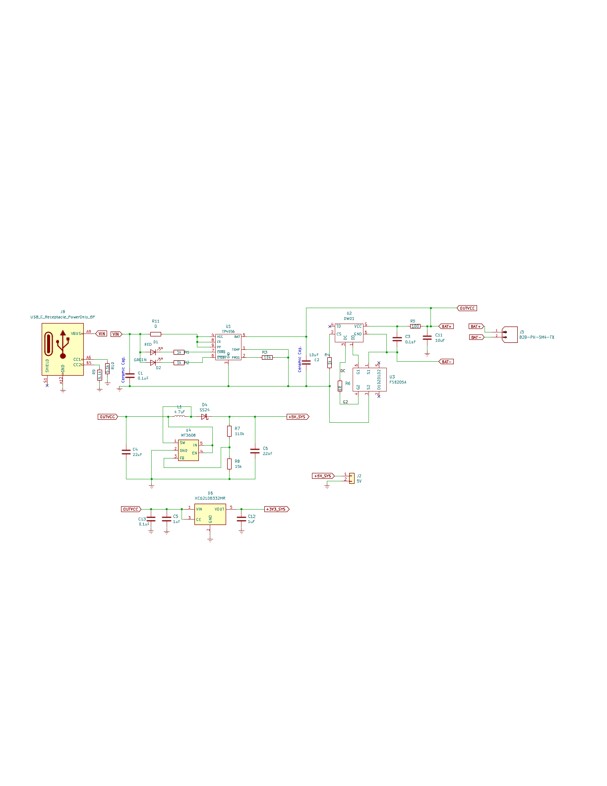
used to measure the charge current as follows: I =V PROG×1200 (V PROG=1V) GND(Pin3): Ground Terminal BAT R PROG Vcc(Pin 4): Positive Input Supply Voltage V INis the power supply to the internal circuit. When VIN drops to within 30mv of the BAT pin voltage, TP4056 enters low power sleep mode, dropping BAT pin’s current to less than 2uA. BAT(Pin5): Battery Connection Pin. Connect the positive terminal of the battery to BAT pin. BAT pin draws less than 2uA current in chip disable mode or in sleep mode. BAT pin provides charge current to
T 42 42 C1024 T 89 48 IC600 T 47 27 L1401 T 55 71 R500 T 128 100 R804 T 34 58 C340 T 143 63 C727 T 145 13 C864 T 65 40 C1025 T 86 25 IC700 T 173 19 L1402 T 29 78 R501 T 114 77 R805 T 50 63 IC701 T 178 7 C341
under con- sideration,sothat the first disc shouldtabilisers reader’s point of view, such programme bat receiver listings take up a great deal of space, contain four or five programmes. and certainly do not make compulsive It is hoped that the Elektor Software programmable address decoder reading. It
4822 520 40044 1 12 44 5.4, S W I T C H A S S E M B L Y N2 printed circuit board 5322 466 10315 1 6 42 Function switch complete 5322 278 80175 2 7 42 V R P P connector X101 5322 267 74125 1 8 42 90 5.5. PRINTED CIRCUIT B O A R D : 5.5.1. Miscellaneous Orderingnumber Qty. Item Fig. Power switch 5322 276
t e e s eee es 15 1 , Temperature measurements... 6.2.6. e cece cece ete e eee ects e e e e e 15 1.42, Frequencymeasurements. 0.6...ses0eeseereece teceeeeeeeeeeeses16 1.13. Relative reference measurements ...... 0.02 0e ec eee eeeee sees e e n s sees 1 6 1.14, Conversion characteristics .. 0.6.0 oe cece
das ESP32-C3 aktuell über USB mit Strom versorge kann ich nicht sagen ob der Prototyp auf BAT funktioniert.. der kritische Punkt ist mE ob der Watchdog zuverlässig die Intervalle hält und ob er sich triggern lässt über Reed-Schaltung und den Pico und BLE zuverlässig anstellt Jede Hilfe dazu
> Zusätzlich soll die Batteriespannung über GPIO26 gemessen werden, die > Schaltung erfolgt mit Bat+ --- 1M --- GPIO26 --- 820 K --- GND Ernsthaft? Datenblätter dienen weder dazu die Festplatte zu befüllen, noch in ausgedruckter Form Tische am Wackeln zu hindern.
...................................................................................................42 6.1 Used symbols.....................................................................................................................................................42 6.2 General pointers...........
...................................................................................................42 MDB, Modulator Data Bit .......................................................................................................................................42 SCEN, Sub-Carrier Enable.............
optimize audio fidelity, and support a wide range of input • Maximum 121 dBuVp RF output level with 42dB audio levels. A low power IDLE mode extends battery life. adjustable range An integrated LDO enables direct connection to the battery and provides high PSRR for superior noise suppression, in • Automatic
immobilizer as an extra security mechanism in their central locking system, which opens the doors, is bat- vehicles. From 1995 it is mandatory that all cars sold in tery powered, operates at a ultra-high frequency (UHF) the EU are fitted with such an immobilizer device, ac- of 433 MHz, and only activates
sollte es doch reichen die 5V vom > ESP-Board dafür zu nutzen? Das ist nicht so richtig toll. An BAT liegt normalerweise die gleiche Spannung, mit der auch der Bus läuft. Die Schwelle für den Empfänger (receiver threshold voltage V_th(rx)) liegen irgendwo zwischen 0.4 ... 0.5 V_Bat @ V_Bat 7.3 ...
2- 40 Die Eingangs ignal-Aufbereitungstastenen für CHANNEL 1 und CHANNEL 2 (LANAL 1 und KANAL 2) 2-42 Überblickcküber das Menü Triggeer/ nsitivity (TriggerZEmpfinmdU keit) 2-42 xi i ili Inhaltsverze chnis Einstellung des Zäa ler-Triggerpegelsmiitden TrrigeerZSensitivity- 2- Tasten (Trigg /Empfindlichkeit
weiteres 40xx/74xx IC-Set, 2 (tr)uSDX Platinensätze, SMD Adapterplatinen, MC33074, originale NXP BF245B, BAT42, ein Dotmatrix-Display, Stiftleisten, Batteriehalter, Sicherungshalter, Schrumpfschlauch, und Ferrithülsen. Falls jemand den (tr)uSDX nachbauen mag, kann er sich gern melden, das ein oder andere
der 1N5817 mit 50µA Ir zu rechnen, vermessen hatte ich ein Exemplar mit 5µA bei 5V. Bitte mal mit BAT42, 1N4148 und 1N4001 simulieren, womit das Minimum am höchsten ist. Oder mit 470nF und 470k das Minimum erhöhen.
gut erhältlich ist, habe ich 10M 47k 2M2 für 0,4µA Teilerstrom vorgeschlagen. Schade, dass kein BAT42 Modell greifbar ist. Bei einer eigentlich schlechteren BAT46 habe ich gerade 0,05µA/5V gemessen. Aber auch mit der 1N4148 sollte es bei V+ 3,3V noch mit einem low level N-FET reichen das Funkmodul
_{DC/DC} ~{ENABLE_{RTC}} ~{ENABLE_{RTC}} ~{ENABLE_{SDCARD}} ~{ENABLE_{SDCARD}} POWERSAVE POWERSAVE BAT DIVIDER BAT DIVIDER C C STAT1 STAT1 STAT2 STAT2 ~{CE} ~{CE} V_{TEMP} V_{TEMP} V_{BACKUPBAT} V_{BACKUPBAT} GPOUT GPOUT SCL SCL SDA SDA GND GND File:mcu.kicad_sch File:power.kicad_sch D D E E H101 MountingHole
LTD. g DDR3 SODIMM B1 Y ▯ Size MS-17631 Number Re2.0 A B C Date: Friday, MarDh 29, 2013 Sheet 11 of 42 ▯ A B C D Lynx Point (HDA,JTAG,SATA) 4 4 +3VALW Y S-BAT54C_SOT23 Z RTCVCC R83 20KR0402 ▯ X C117 C61 C399 C20p50N0402 RTCX1JNC RTC_P2 C1u10X0603 C1u10X0603 2 R182 ▯ 32.768KHZ12.5p_S 10MR1%0402 RTC_P3402
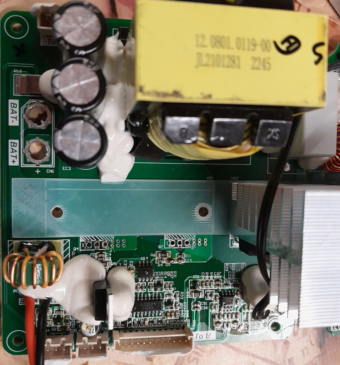
ist eine direkte + Versorgung, ohne Sicherung oder Relais dazwischen. Das BPM hat drei abgesicherte Bat + Eingänge, einer davon wird wohl an die Wischwasserpumpe durchgereicht wenn der Lenkstockschalter betätigt wird. Ich habe jetzt festgestellt dass eine der drei Spannungsversorgungen auf einer durchgebrannten
Guido S. schrieb im Beitrag #7940136: > Das BPM hat drei abgesicherte Bat + Eingänge, einer > davon wird wohl an die Wischwasserpumpe durchgereicht wenn der > Lenkstockschalter betätigt wird. Butt schrieb im Beitrag #7940232: > ists ganz sicher, daß die defekte > Sicherung
> Laut S-Parametertext heißt es "Test Board TB-313": > "The width of the transmission line was 42mil. This was a 4-layer, 50Ω, > controlled impedance board; the dielectric material was FR4, 1oz copper > with a dielectric constant of ~ 4.5. The dielectric thickness between > the top layer and
die .tex-Dateien nirgendwo. Es gab auch keinen Installer, sondern uSimmics wird einfach per start.bat gestartet. Und wieso ist bei Dir keine technical.pdf vorhanden? Was passiert, wenn Du aus uSimmics mittel Strg+F1 die technische Dokumentation öffnest? Bei mir öffnet sich der PDF-Betrachter,
verursacht hat. 2. Mein Regler wird zwar auch etwas warm aber nicht so wie deiner. Eher so 35 - 42 Grad C. Hatte den defekten MOSFET dann raus genommen und dann war der Kurzschluss weg. 3. Aber der Regler scheint nur dafür zu sein um aus der V+ BAT eine geringe Spannung für die notwendigen Bauteile
clips, and two spring hook test probes. (The spade lugs and alligator clips are rated at 30V RMS, 42.4V peak; the test probes are rated at 1000V.) These components are for use with high performance test leads terminated with banana plugs, such as the Model 8605. The following test leads and probes are rated at 30V RMS, 42.4V peak: Models 5805 and 5805-12 Kelvin Probes: Consists of two spring-loaded Kelvin test probes with banana plug termination. Designed for instruments that measure 4-terminal resistance. The Model 5805
install the sampler, press theTART SAMPLING key to run the program. . . . STANDBY . . . Step 10 5:42:23 19-JUN-91 To start the sampling routine with the first bottle, accept the blinking “1” by pressing theR PROGRAM key. If you want to start the routine with another bottle, enter the starting bottle

 Bild
Bild
 Bild
Bild
 Bild
Bild
 Bild
Bild
 Bild
Bild
 Bild
Bild
 Bild
Bild
 Bild
Bild