for Time Signal Application Manufacturer Antenna Type Dimensions Web Link Micro Analog A10X60-77.5K222PY ø 10 x 60 mm http://www.mas- Systems Oy A10X100-77.5K222PY ø 10 x 100 mm oy.com/en/products/radio-controlled- A3.5X4X15-7.87MH 3.5 x 4 x 15 mm clock-rcc/antennas/ A2X3X21-0.92MH 2 x 3 x 21 mm A3.75X3.75X23.6
millis; unsigned char f = timer0_fract; m += MILLIS_INC; f += FRACT_INC; if (f >= FRACT_MAX) { f -= FRACT_MAX; m += 1; } timer0_fract = f; timer0_millis = m; timer0_overflow_count++; } [/code] Dieser Code braucht kaum Zeit, das reicht damit die Genauigkeit der
Paul F. schrieb im Beitrag #8088914: > Budget: 50€ max. Ich glaube, dann ist es am praktikabelsten, die Elektroden alle paar Monate zu reinigen oder zu erneuern.
Paul F. schrieb im Beitrag #8088914: > Budget: 50€ max. 48 Euronen: https://www.manomano.de/p/tauchfahiger-wasserstandssensor-hydrostatischer-drucktransmitter-0-1-m-0-3-3-ft-4-20-ma-ausgang-stabile-genauigkeit-5-m-kabel-24-v-dc-netzteil-tiefensonde-fur-tanks
character generator ROM (code 0101) T6963C−0101 is built in as standard. ▯External display memory : 64 KB Max The addresses in display memory of the text area, graphic area and external character generator area are determined by software. ▯Read or Write operations from the CPU do not disturb the display. ▯A
Danke sehr. WAGO picoMAX ist ein konkreter Hinweis, das hilft mir weiter. Ich werde schauen, dass ich die Steckverbindung entsprechend ersetzen lasse. Hoffentlich ist es tatsächlich "nur" der Kontakt und nicht einer der Antriebe
Wagoklemmen, sieht halt nicht so toll aus, tut aber zuverlässig. Typ 221-2411 (Serie 221) oder Serie 222 gibt's teilweise auch im Baumarkt, geht 1a. Kann man mit ein paar Kabelbindern zugfest machen und gut. Ay schrieb im Beitrag #8086515: > Ich habe auch den HUKLA-Service / POS Service angefragt.
.94 Figure 88: 24-hour HDOP values, in area with with no shadow/obstruction of satellite visibility (max. HDOP < 1.9).......................................95 Figure 89: 24-hour HDOP values, in area with with strong shadow/obstruction of satellite visibility (max. HDOP > 20)............................
Last UHU aus der gelben Tube. Falls es eine Metallbuchse wird, Schraubensicherung Loctite in Rosa (222).
Stephan S. schrieb im Beitrag #8058150: > Das klappt bei kurzen Muttern (max 1-1,5 Gewindegänge) ganz > ausgezeichnet. Das ist ein vollwertiger Ersatz für Kohlewiderstände mit 20% Toleranz.
Das kuriose ist ja, dass die 221-Wagos angeben, ab 0.14 mm² geeignet zu sein, die älteren wuchtigen 222-Wagos dagegen bereits ab 0.08 mm². Hatte mich deswegen nach Datenblattlektüre schon gefreut: Eine Packung Wago-222er kaufen ==> universelle Lösung für alles! (Zumal ich dachte, dass ich damals, ca
Und unisolierte crimpbare Stiftkontakte mit Isolierungsgreifzunge, in AWG 22-28, scheint es nur bis max 8mm Stiftlänge zu geben. Ist auch wieder zu wenig für die Wagos. ?
the counter is full (therefore the counter is also presettable for the DOWN-phase to get a defined max. DOWN-timing in case of a fault). When the DOWN-phase is ready, the contents of the counter is transferred to the output shiftregister and the AZ-phase is started. The timing of the AZ~phase is done
routine examines the Rdown and Rup bits in the range control status register. Ifthe range > range max. then the instrument must range up. Ifthe range < range min. then the instrument must range down. Italso ensures that in the TRIGGER LEVEL function only manual ranging isallowed. 1.4.1.4. M e a s u
button “zero set on/off” 1.6. D C C U R R E N T M E A S U R E M E N T S Ranges :20mA,20mA,2.4,208 (max, input current in highest range) #10 A (20 A for max, 20 sec.) Resolution 510HAin20mArange Number of representation units £2200 Acuracy ++(0.5%ofreading+0.1%offulscale) Temperature coefficient +0.05%
measure anode luminous sensitivity) VOLTAGE 0 V ON LIGHT LEVEL OFF 5 6 7 8 9 (minutes) 1 µA ANODE I max. OUTPUT Ii I min. OR Ii I max. I min. 5 6 7 8 9 (minutes) WARM-UP PERIOD (5 minutes or more) THBV4_0440EA Figure 4-40: Light hysteresis In light hysteresis test, the photomultiplier tube is operated
Max I. schrieb im Beitrag #8033317: > Hans schrieb: >> Müssen größere Querschnitte als >> 4qmm (bei privat allerdings eher selten) geklemmt werden, funktionieren >> die die Steckklemmen nicht mehr,
Max I. schrieb im Beitrag #8033319: > Rolf schrieb im Beitrag #8032737: >> Hans W. schrieb: >>> Es gab mal eine Zeit (als ich ausgebildet wurde), da galten Federklemmen >>> als gefährlicher Pfusch.
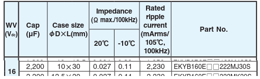
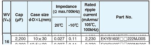
kommen darunter 2 Marken-Elkos mit 2200uF raus: https://www.mouser.de/ProductDetail/Panasonic/EEU-FK1C222L?qs=tfZGHB2PWd22Y%252BsoVqRO3Q%3D%3D https://www.mouser.de/ProductDetail/Chemi-Con/EKYB160ELL222MJ30S?qs=IYueExuAvkr4tdjuXpLB%2Fg%3D%3D
, y a PARTNUMBER/STANDARDCONFIGURATIONS W a Numberof “A” “B” “C” y (10,16) “A” PartNumber Contacts Max. Max. Max. R Max. Max. 1.100 .900 .700 3 514-AG21D 14 (27,49) (22,86) (17,78) 2 . 1.220 1.010 .800 n “C” (2,54) “B” 516-AG21D 16 (30,99) (25,65) (20,32) , Max. Typ. Max. g r e i Note: Before ordering
0°C to +70°C Industrial(I):Tamb = -40°C to BSEL = 0 BSEL = 1 +85°C Symbol Characteristic Min Typ. Max. Min. Typ. Max. Units TE Basic pulse element 260 400 620 130 200 310 μs TBP PWM bit pulse width 3 3 TE TP Preamble duration 28 28 TE TS Sync Pulse duration 10 10 TE TH Header duration 10 10 TE THOP
H2 I H 1 L 0 - 40 0 55 85 125 150 P d Tamb(°C) Note • Zero power is considered as measuring power max. 1 % of max. power. PHYSICAL DIMENSIONS FOR RELEVANT TYPE (all dimensions in millimeters) H1 R25VALUE BMAX. d H2 MAX. L P T MAX. MIN. MAX. 3.3 to 220 5.0 0.6 ± 0.06 1.0 4.0 6.0 24 ± 1.5 2.54 4.0
Main Specifications of the TODX283 Data rate: DC to 50 Mb/s (NRZ code) Transmission distance: 10 m (max) (via APF cable) 100 m (max) (via PCF cable) Pulse width distortion: less than ±7 ns Center wavelength: 650nm Operating temperature: –10°C to 70°C TTL interface TODX283 7 OpticalM odulesforHigh-SpeedDataT
Kopfspiegef an der Lehre anliegt, dund sor dern- gentstärkeregfer an Kgemessen. (Steckerleiste) ge- max. Abstand von 0,1 mm eingehalten uird. lvlassnach lvlS1 Uiedergabe-Pegelkontrolle bei geschlossenem Deckel uiederho.Ien. b) Kopfhöhe Der AIJL-Kopf uird mit der gleichen Lehre so ein- gestellt, daß die
H2 I H 1 L 0 - 40 0 55 85 125 150 P d Tamb(°C) Note • Zero power is considered as measuring power max. 1 % of max. power. PHYSICAL DIMENSIONS FOR RELEVANT TYPE (all dimensions in millimeters) H1 R25VALUE BMAX. d H2 MAX. L P T MAX. MIN. MAX. 3.3 to 220 5.0 0.6 ± 0.06 1.0 4.0 6.0 24 ± 1.5 2.54 4.0
2) Lead Temperature Soldering T °C SLD Reflow (SMD styles only), Leaded, 60−150 s above 183, 30 s max at peak − 240 Reflow (SMD styles only), Lead Free, 60−150 s above 217, 40 s max at peak − 265 Wave Solder (through hole styles only), 12 sec max − 310 2. Per IPC/JEDEC J−STD−020C. Table 4. THERMAL CHARACTERISTICS
) 0° Operating temperature (drive case max °C) 60° † 20°C per hour max (operating) Temperature gradient 35°C per hour max (non-operating) Relative humidity 5% to 95% (operating) 5% to 95% (non-operating) Relative humidity gradient (max) 30%
span Frequency Axis Linear or Log Averaging Displays The following average displays are available: Max Hold Min Hold Average Type of Averaging Exponentialonly Cursorfunctions Number of Cursors One or Two Cursor Modes The following cursor modes are provided: Continuously displayed amplitude and frequency
vor dem Beenden des Setups gespeichert werden. • Administratorkennwort Min • Administratorkennwort Max • Systemkennwort Min • Systemkennwort Max Password Change Bietet Ihnen die Möglichkeit festzulegen, ob Änderungen an den System- und Festplattenkennwörtern erlaubt sein sollen, wenn ein Administratorkennwort
from the center lines is: d2= D aD ·b(0.5 − R· (0.05 + 0.7· exp(−1.6·R) + 0.25·Q − 0.17· lnR)) (12.222) The length of the line in the side arm is: L2= 0.5·max(W ,W )a− db 2 (12.223) where max(x,y) is the larger of the both quantities, R and Q are: ZL,a ·ZL,b f 2 R = Q = ·R (12.224) ZL,2 fp,a·f p,b Turn
das man sieht was passiert. Bügeleisen so einstellen, das es bei etwa 200 Grad abschaltet.(meist max) Im kalten Zustand Platine drauflegen und einschalten. Mit dem Laser Thermometer immer mal schauen wie heiss man ist. Ab 150 Grad gehts los, 180Grad es schmilzt, dann noch so 20-30 Sekunden warten
displayed. displayed. Day (0D to 9999D) T2-1 T1-4 T1-7 MAIN VOL:----- T1-2. POWER-RELAY ON OUTLVL MAX: 00 RST NUM: 00003 Maximum value / The operation frequency of the power relay (RY541) Minimum value / 0 to FF −80.0 to +16.0 dB is displayed. T1-8. PROTECTION LOCK T1-5. POWER OFFTIME-OUT The operation
▯ } I ( ▯ 2 › 2 LED Driver IC ▯ D O ▯ î C ▯ +12V_FAN LED Forward Voltage E 2 2 1 1 SDICS ▯ +15V R_Max 2.4V x 4 pcs = 9.6V L L L L SDI_CLKL ) For EMI ▯ 3 3 3 2 2 2 1 1 1 G_Max 3.3V x 4 pcs = 13.2V C227 C100p50N0402 LED1_G L L L L L L L L L Pin Definerd 6 5 4 3 2 1 O ▯ C567 C100p50N04N2 LED1_R B_Max 3.3V
) Alarm: Once alarm/Everyday alarm:One system each FM S/N ratio: Monaura:l 70dB Sleep: Sleep timer:Max. 90 minutes Stereo:70dB n nGeneral FM THD+N (1kHz) :Monaura: l 0.4% Stereo:0.4% Power supply: (for E2): AC 230 V, 50 Hz / 60Hz (for E1C): AC 220V, 50Hz (for JP): AC 100V, 50/60Hz Power consumption:

 Bild
Bild
 Bild
Bild