1 MCP1640/B/C/D L1 4.7µH VOUT VIN 3.3V @ 100 mA 0.9V to 1.7V SW V OUT VIN C IN 976 K COUT +E 4.7µF V 10µF I EN FB A K 562 K A - GND L1 4.7µH VOUT V IN SW 5.0V @ 300 mA 3.0V to 4.2V V OUTS VIN V OUTP 976 K + CIN C OUT N 4.7µF EN VFB 10 µF O I 309 K L - P GND SGND Efficiency vs. I OUT for 3.3V OUT
Alternativ Bohrungen auf 2,7mm aufbohren und mit Zylinderkopfschraube M2,5 x 8 befestigen. Schaltung. PIC18LF2550 Grundbeschaltung. Schaltplan S. 3/22 Hier kommt ein PIC18LF2550 zum Einsatz. Er verfügt über eine USB-Schnittstelle und ist für Betriebsspannungen von 2 ... 5,5V ausgelegt. Sein Verwandter PIC18F2550
PIN4 = ULN4-->13 = OUT4 = LED_PRG1 = OPTO D In5 = RC0 = PIN11 = ULN3-->14 = OUT6 = LED_PRG2 = OPTO F In6 = RC1 = PIN12 = ULN2-->15 = OUT7 = LED_PRG3 = OPTO G In7 = RA3 = PIN5 = ULN1-->16 = OUT5 = LED_PRG4 = OPT= E TRIAC1 ist nahe dem Zerocross Ofen / Pizzaofen. Leistung und Volumen. Alls Faustformel
fall time froIHV 250 ns All except 24FC256 (Note 1) 15 TOF minimum to VILmaximum 10 + 0.1CB C B 100 pF 250 ns All except 24FC256 (Note 1) Input Filter Spike All except 24FC256 16 TSP Suppression — 50 ns (Notes 1 and 3) (SDA and SCL pins) 17 T WC Write Cycle Time — 5 ms (byte or page) 18 Endurance 1,000,000
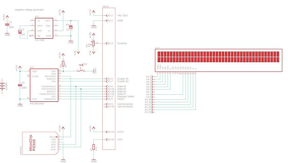
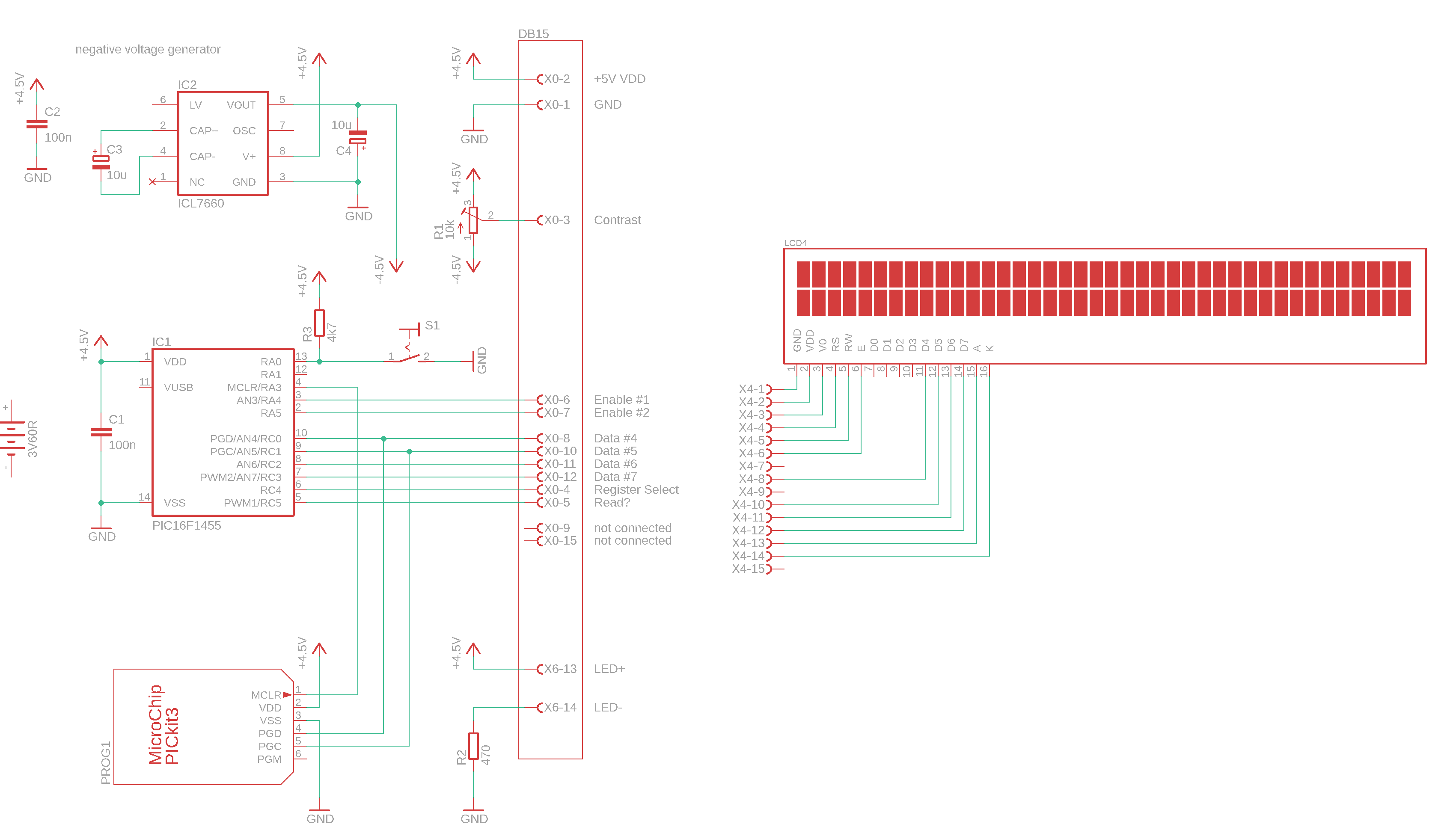
http://kair.us/projects/pickitminus/index.html) da ja der offizielle SUpport eingestellt wurde. Der PIC16F1455 steuert ein 2x40 LCD an, und alles funktioniert wie es soll, wenn das PICkit3 angeschlossen ist. Schaltplan im Anhang. Nach dem Flashen, und der "release from reset"-Modus ist aktiviert, erscheinen
RS, RW, und E sind an die IOs des PIC16F1455 angeschlossen, siehe Schaltplan, somit ist ein Pullup oder Pulldown nicht notwendig. Ausserdem: warum sollte alles funktionieren, wenn das PICkit angeschlossen ist? RS RW und E haben doch nichts
single or two-phase BLDC motor using a combination of Core Independent Peripherals (CIPs) from the PIC16F153XX microcontroller family and a simple low-pass hardware filter. Aside from the capability of successfully driving these low-cost motors, added peripherals on the PIC16F153XX family such as HLT
PIC16F1454, PIC16F1455, PIC16F1459 Code gibts fertig hier: https://github.com/Calcousin55/PIC16F145x_USB2Serial Hab ich selbst schon getestet, Treiber wurde automatisch erkannt.
Niklas schrieb im Beitrag #7505931: > PIC16F1454, PIC16F1455, PIC16F1459 > > Code gibts fertig hier: > https://github.com/Calcousin55/PIC16F145x_USB2Serial > > Hab ich selbst schon getestet, Treiber wurde automatisch erkannt. Das
PIC16F/LF1847/PIC12F/LF1840 PIC16F/LF1847/PIC12F/LF1840MemoryProgrammingSpecification This document includes the 1.1.2 LOW-VOLTAGE ICSP programming specifications for the PROGRAMMING following devices:
feedback capacitor. The corresponding fre- quency domain response is 'out V in " y ^ l - 8 - J t R f -C " •A + 16-jr -f4 R 4 -C 4-A ->+16-JI >f T R ) C ) \ Fig 3.54—Biasing method for high-pass filter sections. A voltage divider creates Eq 3.21 a synthetic ground at half of the single supply. 2.0 1.5
Oszillator an UART > Idealerweise: geht über Arduino oder eine ähnlich einfache > Programmierumgebung PIC16F1454/1455. 14 Pins in DIL/SOIC/TSSOP, 16 Pins in UQFN 4*4mm, Hardware-USB-Device. Hardware UART. Hardware SPI/I2C. 3V3 und 5V-Betrieb möglich fchk
#7331992: > Ich brauche rund 120 IOs über eine ewig lange, sehr schmale PCB > verteilt. Stefan F. schrieb im Beitrag #7332033: > Der STM32L072C8 kann USB und UART ohne Quarz. So einen und dazu 8 x MCP23017 <je 16Pin> (oder ähnliche Portexpander). Damit kannst du über i2c gemütlich jeden Pin
! Hatte mir mal alles > zusammen gekauft, was es da so gab. Wenn Du was kleines haben willst: PIC16F1454, PIC16F1455 oder PIC16F1459. Die haben standardkonformes Full Speed USB in Hardware, und das funktioniert auch. Gibts auch in DIL, funktioniert mit 3.3V und 5V und ist auch sonst einfach zu handhaben
Frank K. schrieb im Beitrag #7317417: > Wenn Du was kleines haben willst: PIC16F1454, PIC16F1455 oder > PIC16F1459. 12 Jahre in Beruf und Hobby mit PIC gearbeitet, sehr zuverlässige Systeme! Habe sogar noch den ICE 3 und MPLAB. Nur Cortex ist einfach besser und so billig
or film capacitors can be used at the output. Figure 4-2 displays a range of ESR values for a 10 µF capacitor. Virtually any 10 µF capacitor with an ESR less than 3.4Ω is sufficient for stability over the FIGURE 4-3: Error FLAG Output Timing. entire input voltage range. Stability can also be 4.5 Thermal
It is necessary for recommended to add a bypass capacitor of 0.1 µF to the capacitor to be located as close as possible to the 1 µF. power pins in order to provide effective noise protection. 6 MCP9501/2/3/SET 2°\C Power Supply Rejection MCP9501/2/3/4 O)5 t( 200Ω ue
23 MCP79400/MCP79401/MCP79402 REGISTER 5-13: ALMxMTH: ALARM0/1 MONTH VALUE REGISTER (ADDRESSES 0x0F/0x16) U-0 U-0 U-0 R/W-0 R/W-0 R/W-0 R/W-0 R/W-1 — — — MTHTEN0 MTHONE3 MTHONE2 MTHONE1 MTHONE0 bit 7 bit 0 Legend: R = Readable bit W = Writable bit U = Unimplemented bit, read as ‘0’ -n = Value at POR
Hallo Ich suche 1-5 Stück des 16f1454 oder 16f1455 als TSSOP-14. Da diese aktuell nicht gut lieferbar sind, hat noch jemand welche die er nicht benötigt ? Gruß
Hallo, machen sie bitte die umsätze mit 16f1455, ist es pic16F1455-I/P Oderpic16F1455-I/ST? Bei unserem unternehmen war der vertrieb für marken wie TI, ST, Microchip,ADI, NORDIC, NORDIC, NXP und infineon ein disziplin,Vielleicht hilft dir das
eingebautem USB-Device. Es geht nicht anders. Entweder portierst Du Deinen Code auf eine andere dsPIC33-Familie wie dsPIC33EP-MU, wie du gesagt hast, oder Du nimmst einen weiteren PIC nur fürs USB - hier würde z.B. ein PIC16F1454 oder PIC16F1455 reichen. https://www.digikey.de/de/products/detail/microchip-technology/PIC16F1454T-I-SL/3879781 https://www.digikey.de/de/products/detail/microchip-technology/PIC16F1455-I-JQ/5033394 fchk
Pin, lässt sich aber gut ein Draht anlöten, weil das breite Stück noch da ist 1x PIC16F870-I/SP 3€ wie neu 1x PIC18F1320-I/P 2,5€ wie neu 1x PIC18F252-I/SP 5€ wie neu 1x PIC18F2550-I/SP 6€ neu 7x PIC18F14K50-I/SS je 2€ neu 6x PIC18LF1320-I/SO je 3€ neu, RS-Components eingeschweißt 1x PIC18LF25K22-I/SO 2€ neu, RS-Components eingeschweißt 3x PIC18F2550-I/SO je 6€ neu, RS-Components eingeschweißt 5x PIC16F1455
=4.7μF cer ( 0.16 IN e 0.14 z a VOUT= 5.0V √ 1.000 I =200 mA o 0.12 VOUT 2.5V V OUT V 0.10 m VR=0.8V,IN =2.1V u 0.08 e o i o 0.06 o 0.100 D 0.04 N 0.02 0.00 0.010 0 50 100 150 200 250 300 0.01 0.1 1 10 100
G0. 5C B 2 F G R G R C2 G 0 O H K 16 2 0 6 Y 0 G B 3 K2 V M 4 1 4 1 A M 2 C G7 E J 2 1 Y 3 K C 6 N C 1 K B K A O S D J A - S 1 1 1 C 0F L R 3 3 Q Q. K 6 0 6 6 X6 83 0 5 4 F 6 G V 1 6 F C G L 1 1 6 NB 1 D T 7 16 2
programming. Use a resistor to pull this pin low when programming. Some Mid-Range parts, such as the PIC16F72/73/74/76/77 family and PIC16F737/747/767/777 family require a minimum programming V DD of +4.75V. Depending on the USB voltage, the PICkit 3 may not be able to supply +4.75V on VDD. Program these parts using an external +5.0V power supply. Some PIC18F parts require significant bypass capacitance on V DD. Try increasing the total bypass capacitance up to 10 µF. PIC18FXXJXX, PIC24X, and dsPIC30F/33F devices require a 4.7 µF capacitor on the VDDCORE
verbesserter Firmware, aber ja, den verwende ich auch gerne. Ist im Prinzip ein vorprogrammierter PIC16F1455. fchk
irgendwelche I2C-Steckkarten usw. kennt > und unterstützt. Das hat Microchip bereits auf einem PIC16F1455 gemacht und verkauft es als MCP2221A. Muss man also nicht mehr selber machen. Ist halt HID statt VCP für I2C und GPIO. fchk
s RISE s t IN ( 25 (75 D1 e y i 20 tFALL l T D65 a 15 n D2 F t 55 n 10 g a a i 5 r45 R P 0 35 -40 -25 -10 5 20 35 50 65 80 95 110 125 4 6 8 10 12 14 16 18 Temperature ( C) Supply Voltage (V) FIGURE 2-3: Rise and Fall Times vs. FIGURE 2-6: Propagation Delay vs.
Margin PM — 70 — ° G = +1 Amplifier Noise Response Input Noise Voltage Eni — 0.67 — µV P-P f = 0.01 Hz to 1 Hz E — 2.1 — µV f = 0.1 Hz to 10 Hz ni P-P Input Noise Voltage Density eni — 102 — nV/√Hz f < 500 Hz Input Noise Current Density ni — 4 — fA/√Hz Amplifier Distortion (Note 1) Intermodulation
Application L1 4.7 µH V OUT VIN SW 3.3V @ 100 mA 0.9V to 1.7V VOUT V IN 976 k + C IN C OUT E 4.7 µF EN V FB 10 µF I A K 562 k A GND - L1 4.7 µH VOUT V IN SW 5.0V @ 300 mA 3.0V to 4.2V V OUTS V IN V OUTP 976 k + CIN COUT 4.7 µF EN VFB 10 µF N - 309 k L - PGND S GND Efficiency vs. I OUT for 3.3V OUT
Current I 90 100 110 mA PROG = 10 kΩ REG Regulation 450 505 550 mA PROG = 2.0 kΩ, Note 1 12.5 14.5 16.5 mA PROG = 67 kΩ T = -5°C to +55°C A Note 1: Not production tested. Ensured by design. 2005-2013 Microchip Technology Inc. DS20001984F-page 3 MCP73831/2 DC CHARACTERISTICS (CONTINUED) Electrical Specifications
SMT pads for easy and reliable PCB • Compatible with Microchip Microcontroller Families mounting (PIC16F, PIC18F, PIC24F/H, dsPIC33 and PIC32) • Class 2 power amplifier with on-board PCB trace antenna (RN42) or external antenna (RN42N) • Up to 10 meter range • Compliance (RN42) Applications - Modular
Product Development, Quicker Time to Market • Compatible with Microchip Microcontroller Fami- lies (PIC16F, PIC18F, PIC24F/H, dsPIC33 and PIC32) • Up to 100 meter range 2021 Microchip Technology Inc. DS50002280B-page 1 RN41/RN41N RN41/RN41 MODULE VARIANTS (1) Model Antenna Firmware Description RN41
2-16: Dropout Voltage vs. Temperature. Junction Temperature. 5.01 VIN 3.8V IL= 150 mA VOUT 2.8V 5.00 COUT 1 µF Ceramic V Frequency = 1 kHz ( 4.99 g 4.98 100mV/DIV VOUT t o 4.97 L = 100 mAIL= 0.1 mA V u 4.96
1μH L1 1μH 2.5V to 5.0V SW 2.5V to 5.0V SW V V V V IN IN OUT OUT IN IN OUT 5.0V C1 R1 5.0V C1 R1 4.7μF 1MΩ C2* 4.7μF 1MΩ R2 C2* 10V EN /PG VIN 22μF 10V EN /PG VIN 910kΩ 22μF 10V OUTS 10V FB R3 200kΩ PGND AGND PGND AGND * Two more 22 F capacitors should be added in parallel with C2 for V IN > 5.0V. Efficiency

 Bild
Bild