-
PDF
dokserv.pdf
πnfDDSqm X nf +qf = 1 ⋅ fDDS ⋅J π m ′nf DDS + qfm ⋅ j( )1 qe fDDS DDS m 2π nfDDS + qf m q fC (4.50) 1 f nf + qf X nf qf = ⋅ DDS ⋅Jq πm ′ DDS m DDS m 2π nfDDS + qfm fC Abb. 4.23 zeigt beispielhaft das durch die Gl. (4.47
-
Datei
DDS_Funktionsgenerator.c
(dds_status *dds); void dds_status_speichern(dds_status *dds); int main(void) { dds_status dds; uint8_t refresh = 1; uint8_t display_mode = 0; //0=Offset, 1=Amplitude uint8_t taster; uint8_t drehgeber_mode
in „Funktion bekommt keinen Wert übergeben“ · Mikrocontroller und Digitale Elektronik ·
-
Datei
DDS.c
//includes ////////// #include "avr/io.h" #include <util/delay.h> //defines ///////// #define DDS_MCLK 24000000 /* DDS Clock */ #define DDS_CONSTANT 0x10000000 /* 2^28 */ #define DDS_DDR DDRD /* data direction reg*/ #define DDS_PORT PORTD #define DDS_SDATA PIN0 #define DDS_SCLCK PIN1 #define DDS_FSYNC
-
PDF
dds_ds558.pdf
LogiCORE IP DDS Compiler v4.0 DS558 April 19, 2010 Product Specification • Frequency and phase offset may be independently Introduction configured as constant, programmable or dynamic The LogiCORE™ IP DDS (Direct Digital
-
PDF
silo.tips_kondensations-lten-fr-jedermann.pdf
Mengen über DK4DDS bezogen werden. Marc van Stralen, DK4DDS, Schulstrasse 21 D-48455 Bad Bentheim /Gildehaus Duitsland T:+49(0)5924-997337 E: dk4dds@t-online.de info@imdes.de I: www.qslnet.de/dk4dds www.imdes.de SKYPE
in „BGA verlöten“ · Platinen ·
-
Datei
DDS.c
//includes ////////// #include "avr/io.h" #include <util/delay.h> //defines ///////// #define DDS_MCLK 24000000 /* DDS Clock */ #define DDS_CONSTANT 0x10000000 /* 2^28 */ #define DDS_DDR DDRD /* data direction reg*/ #define DDS_PORT PORTD #define DDS_SDATA PIN0 #define DDS_SCLCK PIN1 #define DDS_FSYNC
in „Daten zum AD9833 in C übertragen“ · Mikrocontroller und Digitale Elektronik ·
-
PDF
5991-0852.pdf
TECHNICAL O V E R V I E W Direct Digital Synthesis (DDS) Generators versus Trueform Waveform Generators The incumbent technology used in most function generators is known as direct digital synthesis (DDS). Unfortunately, DDS has a number of problems that
in „“point per clock” (PPC) generation“ · Mikrocontroller und Digitale Elektronik ·
-
Datei
SPI_set_dds.c
void SPI_set_dds(u32 f_dds) // Frequency in Herz //--------------------------------------------------- // Set DDS-output frequency to [f_dds] Hz // f_dds = 0 will set the DDS into PowerDown Mode // f_dds = 1..45'000'000
in „Formel Mikrocontrollergerecht machen“ · Mikrocontroller und Digitale Elektronik ·
-
Datei
Master_text.txt
Dim Long_adder As Long Dim Str_temp As String * 20 Dim Str_uart As String * 20 Dim Command As Byte ' DDS variables Dim DdsCrystal As Double ' TWI Slave (DDS) crystal DdsCrystal = 16000000 Dim Dds_adress As Byte Dim Ddsregister As Byte Dim Ddsvalue As Byte Dim Frequency As Double ' Hz Dim Last_frequency
in „DDS normal ?“ · Mikrocontroller und Digitale Elektronik ·
-
PDF
Schematic_Prints.pdf
1 SYNC_IN R506 C562 25MHz dnp 2 SYNC_OUT CH1_IOUT 13 DDS11_P 1V8_DDSA 100nF 100nF 100nF 100nF DDS_IO_UPD 46 I/O_UPDATE R507 60 CH1_IOUT 14 DDS11_N 47 60 AGND DDS_CS CS 40 L506 L507 L508 DDS12_P DDS_PS0 41 PS0 27 10mH 10mH 10mH DDS12_P DDS_PS1 42 PS1 LOOP_FILTER R508 DDS_PS2 43 PS2 R509 C510C511 C512C513 C514C515 C516C517 C DDS_PS3 PS3 0 100pF100pF 100pF100pF 100pF100pF 100pF100pF 1K C L509 L510 L511 DDS_RST 3 RESET D D D D D D D D D DDS12_N DDS12_N DDS_PD 4 PWR_DN_CTL
in „DDS AD9958 - Probleme mit dem extrahieren des Chips“ · Mikrocontroller und Digitale Elektronik ·
-
Datei
dualMotorPll.c
/////////////////////////////////////////////////// // enum { DDS_WAVE_TIME_BITS =8, ///< PWM amplitude resolution bits DDS_WAVE_TIME =1<<DDS_WAVE_TIME_BITS, SINE_TABLE_BITS =8, DDS_F_SAMPLE =31250, DDS_TUNE_1HZ =( (1llu<<32) + DDS_F_SAMPLE/2 )/DDS_F_SAMPLE, //137439
in „Wechselrichter zur Netzeinspeisung bauen?“ · Analoge Elektronik und Schaltungstechnik ·
-
PDF
DDS20_KM_G_030523.pdf
Bau- und Bedienungsanleitung Best.-Nr.: 47138 Version 4.0, Stand: Mai 2003 20-MHz-DDS-Board DDS 20 Technischer Kundendienst Für Fragen und Auskünfte stehen Ihnen unsere qualifizierten technischen Mitarbeiter gerne zur Verfügung. ELV • Technischer Kundendienst • Postfach 1000 • D - 26787
in „AD811 Bezug für ELV DDS20“ · Mikrocontroller und Digitale Elektronik ·
-
PDF
DDS20_KM_G_030523.pdf
Bau- und Bedienungsanleitung Best.-Nr.: 47138 Version 4.0, Stand: Mai 2003 20-MHz-DDS-Board DDS 20 Technischer Kundendienst Für Fragen und Auskünfte stehen Ihnen unsere qualifizierten technischen Mitarbeiter gerne zur Verfügung. ELV • Technischer Kundendienst • Postfach 1000 • D - 26787
in „Welcher Microcontroller ist das, DSS20 ELV?“ · Mikrocontroller und Digitale Elektronik ·
-
PDF
Basic_Practical_of_Transmission_Line_Theory_transmis__TI.pdf
of the signal. In this case it is allowed to use the simplified capacitive load line model. FOPE \DDS\TraAug96.ppt Digital Design Seminar Typical Line Impedances FOPE \DDS\Transmis.Aug96 Digital Design Seminar Waveforms with Transmission Lines and Capacitive Load FOPE \DDS\Transmis.Aug96 Digital Design
in „Anfrage zur Bandbreite eines Oszilloskopes“ · Mikrocontroller und Digitale Elektronik ·
-
Datei
system_operation.c
with prescaler setting ret_flag = FALSE; // Clear flag and do nothing } while(ret_flag); uint64_t dds_clk; // DDS clock frequency if(!status.extref) // Is the internal frequency reference used? dds_clk = ( int_ref + get_fcorr_val() ) * dds_mult; // Then calculate corrected DDS clock else dds_clk = int_ref * dds_mult; // For external reference use uncorrected DDS clock uint32_t dds_tunewd = (uint32_t)( lroundf( f_dds * pow2(32) / dds_clk ) ); // Determine DDS tune word dds_write_tunewd(dds_tunewd); // Write
in „Oszillator YIG 1,9-4,4 GHz Avantek ASF-9882/7841“ · HF, Funk und Felder ·
-
PDF
DDS_Tutorial_Section7.pdf
changed frequently or rapidly and that have no integer relationship with each other? This is where the DDS shines! With a single pN-1ise pulse train that times the assembly of new sine wave samples, the DDS can output 2 discrete frequencies (where N is the DDS resolution in bits). These frequencies range
in „auf einfache Weise von 11MHz auf 300kHz teilen/generieren“ · Mikrocontroller und Digitale Elektronik ·
-
PDF
Frequenzmessung_mit_dem_VNWA_015c.pdf
nichts zu tun. Im TX Offset spiegelt sich lediglich die Tatsache wieder, dass mit dem vorgegebenen DDS-Kanalraster bei vorgegebenen Takten die nominale ZF u.U. nicht exakt erzeugbar ist. Die Referenz ist immer die TX DDS. Der TX Offset sagt also lediglich, wie weit die TX DDS neben der nominalen Frequenz
in „DIY Frequency Counter mit 10 bis 12 Digits?“ · Mikrocontroller und Digitale Elektronik ·
-
PDF
ADD9910_Design.pdf
IMPLIED WARANTEE GIVEN. U? VDD_4V PIU?01 PIU?10 PR0? PR0 VC _ V8_AVDD 2 IN OUT POVCC_1V8_AVDDAV DD DDS_Modul_Supply_2[4F], DDS_Modul PIU?02 IN 0 F R? OUTS PIU?09 F PI PR01 PR0 PIU?03 EN/UV C? PIU?04 P2 VCC_3V3_µC PI Cap 0 6 PG C? 10µF PIU?06 PGFB 5 P1Cap U? R? ILIM PIU?05 VDD_4V PIU?0 PIU010 PI?1 PI?
in „PCB -Frequenzrampe 100khz-360 MHz“ · Analoge Elektronik und Schaltungstechnik ·
-
Datei
DDS_func.cpp
; } DLL_EXPORT int DDS_close (){ FT_STATUS status = 0; status = SPI_Close (SPI_Device); return status; } DLL_EXPORT int DDS_write_FREQ (double frequency){ FT_STATUS status = 0; unsigned int DDS_Ctrl_Reg_MSB = 0; unsigned int DDS_Ctrl_Reg_LSB = 0; unsigned int DDS_Reset = 0; unsigned int DDS_Ctrl_Reg = 0; unsigned long FREQ0_REG = 0x4000; unsigned long FREQ1_REG = 0x8000; unsigned long LSB_MASK = 0x003fff; unsigned long MSB_MASK
in „DDS 9958 reagiert nicht“ · Mikrocontroller und Digitale Elektronik ·
-
PDF
ADS1256.pdf
(dds, b'\x02\x00\x00') # ASF write Amplitude Scale Factor (16 bit) pi.spi_write(dds, b'\x03\x00') # ARR write Amplitude Ramp Rate (8 bit) pi.spi_write(dds, b'\x05\x00\x00') # POW write Phase Offset Word
in „Kommunikation mit AD-Wandler ADS1255“ · Mikrocontroller und Digitale Elektronik ·
-
PDF
SDR-CQDL-02.pdf
Zusammen mit einem SDR-Empfängermodul ähnlich dem SoftRock wird aus Japan von JA7TDO eine preiswerte DDS-Baugruppe mit der Bezeichnung DDS-34B angeboten [8]. Diese Baugruppe nutzt von Analog Devices den AD9834. Es wird der DDS auf die Empfangsfrequenz programmiert, zur Ansteuerung der Teilerkette wird
-
PDF
AD9952arduino.pdf
LCD-Display: Busy-Flag = Bit3 von PortC 60 .equ EncStp = 1 ; EncoderStep 61 ; 62 .equ RESET = 0 ; DDS-Serial: RESET = Bit0 von PortB 63 .equ nCS = 1 ; DDS-Serial: /CS = Bit1 von PortB 64 .equ IOupd = 2 ; DDS-Serial: I/O-UPDATE = Bit2 von PortB 65 .equ SDIO = 3 ; DDS-Serial: SDIO = Bit3 von PortB =MOSI
in „DDS-Chip mit einem AVR ansprechen“ · Mikrocontroller und Digitale Elektronik ·
-
Datei
top.vhd
); end component; signal dds_control_word_i : STD_LOGIC_VECTOR (31 downto 0); signal dds_scaling_word_i : STD_LOGIC_VECTOR (4 downto 0); signal freq_out_i : STD_LOGIC; signal counter_i : STD_LOGIC_VECTOR (7 downto 0); begin fg0 : Frequency_Generator port map ( dds_control_word => dds_control_word_i, dds_scaling_word => dds_scaling_word_i, RESET => BTN(0), CLK => CLK_50M, FREQ_OUT => freq_out_i ); process(CLK_50M) begin if (rising_edge(CLK_50M)) then dds_control_word_i
-
Datei
code.c
include <mega8.h> #include <alcd.h> #include <stdio.h> #include <delay.h> #define RESET PORTD.0 // Ïîðòû DDS îïîðíèêà #define SCLK PORTC.1 // ñòðîá DDS #define FSYNC PORTC.3 // îáíîâëåíèå äàííûõ â DDS #define SDATA PORTC.2 // äàííûå DDS #define FU_UD PORTC.0 // îáíîâëåíèå äàííûõ â AD9850 #define DATA PORTD
in „C-Datei in hex“ · Mikrocontroller und Digitale Elektronik ·
-
PDF
S1L50282F23K200.pdf
R - - - - - - R1 - - - - - - Note1: These dimensions are for reference. NEC LCD Technologies, Ltd. DDS-SA10747 16/24 Package Marking Unit: mm NEC LCD Technologies, Ltd. DDS-SA10747 17/24 13. RELIABILITYTEST No. TEST ITEM TEST CONDITION STANDARD CRITERIA EIAJ-ED-4701 Ta=120°C, 1 High temperature with
in „LCD Timing-Controller gesucht“ · Mikrocontroller und Digitale Elektronik ·
-
PDF
ADD9910_Design.pdf
RIGHTS ARE RESERVED OR EXPRESS OR IMPLIED WARANTEE GIVEN. F F E E Designator Supply.SchDoc Designator DDS_AD9910_and_uC.SchDoc Designator D DDS_Modul_Multiplier.SchDoc D VCC_3V3 VCC_3V3 RF_OUT1_P RF_OUT1_P VCC_3V3_µC RF_OUT1_N RF_OUT1_N Designator DDS_Modul_Supply_AD9910.SchDoc C C VCC_1V8_AVDD VCC_1V8_
in „PCB -Frequenzrampe 100khz-360 MHz“ · Analoge Elektronik und Schaltungstechnik ·
-
Datei
btflydds_9851_rig.asm
set up serial periferial interface register ldi temp,$70 out spcr,temp rjmp initreg ;initialize 9850 dds for serial mode init_dds: sbi portb,ddsen ;set enable pin high nop cbi portb,ddsen ;clear enable pin nop sbi portb,clock ;set clock pin high nop cbi portb,clock ;clear clock pin nop sbi portb,ddsen
in „ATMEGA8 + AD9833 + Nokia 3310 LCD“ · Mikrocontroller und Digitale Elektronik ·
-
Datei
LineIntoLineOutAndDACsEFRwithTermWithScope2.ino
si5351.set_freq(hilfsf, Si_5351_clock); } float Tsample=1.0/Fsample ; float DDStable[256] ; int32_t DDS1phase ; int32_t DDS1frequency ; float DDS1s ; float DDS1c ; void DDS1step(){ DDS1phase += DDS1frequency ; int index=(DDS1phase>>24)&0xFF ; DDS1c=DDStable[ index ] ; DDS1s=DDStable[ (index+64)&0xFF ]
in „Empfänger nach DD4WH mit Fast Convolution“ · Digitale Signalverarbeitung / DSP / Machine Learning ·
-
Datei
dds_50.vhd
library IEEE; use IEEE.STD_LOGIC_1164.ALL; library UNISIM; use UNISIM.VComponents.all; entity dds_50 is Port ( CLKIN : in STD_LOGIC; SINEOUT : out STD_LOGIC_VECTOR (7 downto 0); FTW : in STD_LOGIC_VECTOR (15 downto 0)); end dds_50; architecture Behavioral of dds_50 is component dds_core port ( clk
-
Datei
LineIntoLineOutAndDACsDDHwithTermWithScope1.ino
si5351.set_freq(hilfsf, Si_5351_clock); } float Tsample=1.0/Fsample ; float DDStable[256] ; int32_t DDS1phase ; int32_t DDS1frequency ; float DDS1s ; float DDS1c ; void DDS1step(){ DDS1phase += DDS1frequency ; int index=(DDS1phase>>24)&0xFF ; DDS1c=DDStable[ index ] ; DDS1s=DDStable[ (index+64)&0xFF ]
in „Empfänger nach DD4WH mit Fast Convolution“ · Digitale Signalverarbeitung / DSP / Machine Learning ·
-
Datei
dds-pll.asm
temp , so same subroutines can be used in Int and main in tmp,UDR ; rjmp pllmode cpi tmp,'s' ; 32 bit DDS (Sinus ,no quadrature) brne tx_2 rjmp dds_fast ; jump to cold restart tx_2: cpi tmp,'q' ; 32 bit DDS (Sinus + Quadrature, slower) brne tx_3 rjmp ddsquad ; jump to cold restart tx_3: cpi tmp,'p' ; PLL
in „PLL mit Atmega8 läuft + Fragen!“ · Mikrocontroller und Digitale Elektronik ·
-
Datei
Multi_Pulse_Gen_DDS.ino
in Grad, 0-360 uint8_t setPhase(uint16_t phaseDeg) { return (phaseDeg * 256L) / 360; } // Reset des DDS Akkus muss atomar sein, damit die Phasenlage garantiert ist // Außerdem sind die Akkus 16 Bit und damit nicht atomar auf einem kleinen 8 Bit AVR // Erst Frequenz und Phase definieren, danach resetDDS
in „Arduino Timerprobleme - suche programmierbaren Oszillator“ · Mikrocontroller und Digitale Elektronik ·
-
PDF
Hauptplatine.pdf
FSW-B ATT-D1 SLE SCK SLE SCK FSW-C FSW-B ATT-D2 ATT-D1 SLE SLE FSW-C ATT-D2 CS-Ref-PLL CS-Ref-PLL CS-DDS CS-DDS ATT-D3 ATT-D3 CS-M-PLL ATT-LE Unlvld Int-Sel CS-M-PLL M-Lock ATT-LE Unlvld Int-Sel M-Lock B Ext-Sel Ext-Sel Ref-Lock Ref-Lock DDS-Reset DDS-Reset PLL-Mux PLL-Mux Level-Ctrl DAC Level-Ctrl File: reference.sch File: pll-dds.sch File: filter.sch File: leveling.sch +3.3V Sheet: Controller J3 1 ISP UPDI DAC Connector 2 3 SDA 4 C1 SDA SCK SCK 5 100n SLE SLE 6 CS-Ref-PLL CS-Ref-PLL C CS-M-PLL GND CS-M-PLL CS-DDS CS-DDS FSW-A
in „Oszillator YIG 1,9-4,4 GHz Avantek ASF-9882/7841“ · HF, Funk und Felder ·
-
Datei
Bell202Modem.asm
ausgeben ldi R19,high(DDS2200) rjmp Phase Phase1: ldi R18,low(DDS1200) ; Niederige Frequenz ausgeben ldi R19,high(DDS1200) Phase: lds R16,PhaseAccu ; Auf Phasenakku addieren lds R17,PhaseAccu+1 add R16,R18 adc R17,R19 sts PhaseAccu
in „AVR als Demodulator Mdulator eines Modemsignals“ · Mikrocontroller und Digitale Elektronik ·
-
Datei
Frequency_Generator.vhd
unisim_VCOMP.vhd -- library UNISIM; use UNISIM.Vcomponents.ALL; entity Frequency_Generator is port (dds_control_word : in std_logic_vector (31 downto 0) := X"10000000"; -- 100 MHz dds_scaling_word : in std_logic_vector (4 downto 0) := "00000"; RESET : in std_logic; CLK : in std_logic; FREQ_OUT : out std_logic
-
Datei
toplvl.vhd
d_in : OUT std_logic; cs : OUT std_logic; sclk_out_LTC : OUT std_logic ); end component; component DDS port (clk: IN std_logic; sine: OUT std_logic_VECTOR(15 downto 0) ); end component; -- Synplicity black box declaration attribute syn_black_box : boolean; attribute syn_black_box of DDS: component is
-
Datei
dds_testbench.vhdl
library ieee; use ieee.numeric_std.all; use ieee.std_logic_1164.all; entity dds_test is end entity dds_test; architecture test of dds_test is component dds is port(clk : in std_logic; incr : in unsigned(31 downto 0); res : out unsigned(7 downto 0)); end component; signal incr :
-
Datei
main.c
initSPI(); data = 0b01010101; //LED_On(LED_BLUE); //data = 0b0000000100000000; // Reset der Register //DDS_write(data); //data = 0b0001000000000000; //MSB und LSB werden einzeln beschrieben MSB in diesem Fall / Sinus //DDS_write(data); //LED_On(LED_ORANGE); //data = 0b0100000000000000; //MSB für 1kHz //DDS_write
in „AD9833 mittels STM32F072 per SPI ansteuern“ · Mikrocontroller und Digitale Elektronik ·
-
Datei
Master.txt
dbl_Temp As Double Dim Long_ADDER As Long Dim Str_UART As String * 10 Dim Command As String * 1 ' DDS variables Dim DDSCrystal As Double ' TWI Slave (DDS) crystal DDSCrystal = 22000000 Dim FREQUENCY As Double ' Hz Dim MODUS As Byte Dim DUTY as Byte ' ' r24,r25,r26,r27 is the ADDER value determining
in „DDS Sinus erzeugung“ · Mikrocontroller und Digitale Elektronik ·
-
Datei
DDS_tb.vhd
library IEEE; use IEEE.std_logic_1164.all; use IEEE.NUMERIC_STD.all; entity DDS_TB is -- a test bench has no ports! end DDS_TB; architecture BEHAVIOUR of DDS_TB is -- my device under test component DDS port ( CLK : in std_logic; -- main clock the same as SCK for PCM5142 FREQ_INC
in „DDS mit DE0-Nano Board nur niedrige Frequenzen?“ · FPGA, VHDL & Co. ·
-
Datei
display.asm
* ;* Um die Umschaltstörungen der DDS Signale kurz zu halten wird eine schnelle ;* Kommunikation via RS232 angewendet. ;* Der DDS uC antwortet mit 3 Bytes des gespeicherten Phasenincrements. ;* im Steuer uC wird dann die Frequenz ausgerechnet
in „LCD Routine Funktioniert nicht“ · Mikrocontroller und Digitale Elektronik ·
-
Datei
PCM_master.vhd
(20 downto 0) ) ; end PCM_MASTER; architecture BEHAVIOUR of PCM_MASTER is -- instance of component DDS is here component DDS port ( CLK : in std_logic; -- main clock the same as SCK for PCM5142 FREQ_INC : in std_logic_vector (7 downto 0); BCK : in std_logic; DIN_CNT : in integer; DOUT : out std_logic_vector
in „DDS mit DE0-Nano Board nur niedrige Frequenzen?“ · FPGA, VHDL & Co. ·
-
Datei
162_ICP_DDS_01.c
4,5 sec detektiert? Warnanzeige an und Therapiesignal aus if (NrOverflows > 1 ) { DDRB = 0x00; // DDS Signal aus DDRA = (1<<PA0)|(1<<PA1); // "kein Signal"Warn LED PA0 an, Betriebsanzeige an } // liegt eine vollständige Messung vor? else if(Pulsmess) { DDRB = 0xFF; // DDS Signal an DDRA =(0<<PA0)|(1
in „Atmega162 außerhalb von STK500 geht nicht“ · Mikrocontroller und Digitale Elektronik ·
-
Datei
162_ICP_DDS_02.c
4,5 sec detektiert? Warnanzeige an und Therapiesignal aus if (NrOverflows > 1 ) { DDRB = 0x00; // DDS Signal aus PORTA = (1<<PA0)|(1<<PA1); // "kein Signal"Warn LED PA0 an, Betriebsanzeige an } // liegt eine vollständige Messung vor? else if(Pulsmess) { DDRB = 0xFF; // DDS Signal an PORTA =(0<<PA0)|
in „DDS Signal stoppt nicht bei ICP ohne Eingang“ · Mikrocontroller und Digitale Elektronik ·
-
 Bild
Bild
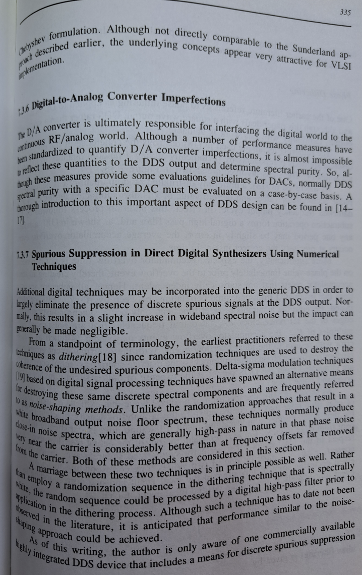
Foto einer Buchseite über D/A-Wandler und DDS
to quantify D/A converter imperfections, it is almost impossible to reflect these quantities to the DDS output and determine spectral purity. So, al- though these measures provide some evaluations guidelines for DACs, normally DDS spectral purity with a specific DAC must be evaluated on a case-by-case basis. A thorough introduction to this important aspect of DDS design can be found in [14- 17]. 7.3.7 Spurious Suppression in Direct Digital Synthesizers Using Numerical Techniques Additional digital techniques may be incorporated into the generic DDS in order
in „Genauer und schneller Sinus im FPGA“ · FPGA, VHDL & Co. · · Fotos
-
Datei
DDS.h
#ifndef DDS_H_ #define DDS_H_ /// <summary> /// Author: Florian Asal /// Date: 2012.10.17 /// /// Using an adc speed of 48000Hz, which means that we can output 48000 values per second. To save storage /// The output
in „DDS performance code Ausführung“ · Digitale Signalverarbeitung / DSP / Machine Learning ·
-
Datei
ad5932.h
0x01 #define TIMEBASE_MULTILPLIER_X100 0x02 #define TIMEBASE_MULTILPLIER_X500 0x03 #define SYNCOUT_DDS1 ((IOPIN0 & 0x00080000)>0) #define DDS1 1 unsigned int control_reg; unsigned int tb_multiplier; unsigned int tb_mult; unsigned int n_inc; unsigned int t_int; unsigned long delta_f; unsigned long startfrequenz,endfrequenz_dds1,wobbelfrequenz_dds1; //unsigned long mclk; unsigned int sweep_delay; // sweep delay in s unsigned short sweep_status; float scandurchlauf; double mclk_faktor; unsigned long startdelay; void ad5932_
in „DDS-Singalgenerator mit ATmega88 und DDS AD5932“ · Digitale Signalverarbeitung / DSP / Machine Learning ·
-
Datei
ad5932.h
0x01 #define TIMEBASE_MULTILPLIER_X100 0x02 #define TIMEBASE_MULTILPLIER_X500 0x03 #define SYNCOUT_DDS1 ((IOPIN0 & 0x00080000)>0) #define DDS1 1 unsigned int control_reg; unsigned int tb_multiplier; unsigned int tb_mult; unsigned int n_inc; unsigned int t_int; unsigned long delta_f; unsigned long startfrequenz,endfrequenz_dds1,wobbelfrequenz_dds1; //unsigned long mclk; unsigned int sweep_delay; // sweep delay in s unsigned short sweep_status; float scandurchlauf; double mclk_faktor; double mclk; unsigned long startdelay;
in „DDS-Singalgenerator mit ATmega88 und DDS AD5932“ · Digitale Signalverarbeitung / DSP / Machine Learning ·
-
Datei
ad5932.h
0x01 #define TIMEBASE_MULTILPLIER_X100 0x02 #define TIMEBASE_MULTILPLIER_X500 0x03 //#define SYNCOUT_DDS1 ((IOPIN0 & 0x00080000)>0) #define DDS1 1 unsigned int control_reg; unsigned int tb_multiplier; unsigned int tb_mult; unsigned int n_inc; unsigned int t_int; unsigned long delta_f; unsigned long startfrequenz,endfrequenz_dds1,wobbelfrequenz_dds1; //unsigned long mclk; unsigned int sweep_delay; // sweep delay in s unsigned short sweep_status; float scandurchlauf; double mclk_faktor; double mclk; unsigned long startdelay;
in „DDS-Singalgenerator mit ATmega88 und DDS AD5932“ · Digitale Signalverarbeitung / DSP / Machine Learning ·
-
Datei
ad5932.h
0x01 #define TIMEBASE_MULTILPLIER_X100 0x02 #define TIMEBASE_MULTILPLIER_X500 0x03 //#define SYNCOUT_DDS1 ((IOPIN0 & 0x00080000)>0) #define DDS1 1 unsigned int control_reg; unsigned int tb_multiplier; unsigned int tb_mult; unsigned int n_inc; unsigned int t_int; unsigned long delta_f; unsigned long startfrequenz,endfrequenz_dds1,wobbelfrequenz_dds1; //unsigned long mclk; unsigned int sweep_delay; // sweep delay in s unsigned short sweep_status; float scandurchlauf; double mclk_faktor; double mclk; unsigned long startdelay;
in „Projekt: DDS basierter Funktionsgenerator mit AD5930“ · Mikrocontroller und Digitale Elektronik ·