-
Datei
source.txt
EEMEM; uint8_t MidiKanalTaster3; uint8_t MidiKanalTaster4imEeprom EEMEM; uint8_t MidiKanalTaster4; uint8_t MidiKanalTaster5imEeprom EEMEM; uint8_t MidiKanalTaster5; uint8_t MidiKanalTaster6imEeprom EEMEM; uint8_t MidiKanalTaster6
in „Kann vllt jemand mein erstes Programm kontrollieren“ · Mikrocontroller und Digitale Elektronik ·
-
Datei
MidiOutTest.c
_t c) { loop_until_bit_is_set(UCSRA, UDRE); UDR = c; _delay_ms(1); } // Midi tones void MidiAllOff() { MidiSend(0); MidiSend(0); MidiSend(0x7F); } void MidiNoteOn(uint8_t channel, uint8_t tone,uint8_t velocity) { MidiSend(0x90 | (channel & 0x0F)); // Note on & channel MidiSend
in „MIDI-Protokoll“ · Mikrocontroller und Digitale Elektronik ·
-
Datei
polymcv_c.htm
by clearing it. if ((byte == (NOTE_ON + midi_chan)) || (byte == (NOTE_OFF + midi_chan)) || (byte == (CHANMODE + midi_chan)) || (byte == (PITCH + midi_chan)) || (byte == (AFTERTOUCH + midi_chan)) ) { // if its a byte we want to know about midi_status = byte ; // set running status byte midi_char_count = 0 ; } } else { if ((midi_status == (NOTE_ON + midi_chan)) || (midi_status == (NOTE_OFF + midi_chan)) || (midi_status == (CHANMODE + midi_chan)) || (midi_status == (PITCH + midi_chan)) |
in „kompilieren von C-Quellcode“ · Mikrocontroller und Digitale Elektronik ·
-
Datei
FT800.h
29 #define FT_MIDI_F_1 30 #define FT_MIDI_G1 31 #define FT_MIDI_G_1 32 #define FT_MIDI_A1 33 #define FT_MIDI_A_1 34 #define FT_MIDI_B1 35 #define FT_MIDI_C2 36 #define FT_MIDI_C_2 37 #define FT_MIDI_D2 38 #define FT_MIDI_D_2 39 #define FT_MIDI_E2 40 #define FT_MIDI_F2 41 #define FT_MIDI_F_2 42 #define FT_MIDI_G2 43 #define FT_MIDI_G_2 44 #define FT_MIDI_A2 45 #define FT_MIDI_A_2 46 #define FT_MIDI_B2 47 #define FT_MIDI_C3 48 #define FT_MIDI_C
-
Datei
FT800.h
29 #define FT_MIDI_F_1 30 #define FT_MIDI_G1 31 #define FT_MIDI_G_1 32 #define FT_MIDI_A1 33 #define FT_MIDI_A_1 34 #define FT_MIDI_B1 35 #define FT_MIDI_C2 36 #define FT_MIDI_C_2 37 #define FT_MIDI_D2 38 #define FT_MIDI_D_2 39 #define FT_MIDI_E2 40 #define FT_MIDI_F2 41 #define FT_MIDI_F_2 42 #define FT_MIDI_G2 43 #define FT_MIDI_G_2 44 #define FT_MIDI_A2 45 #define FT_MIDI_A_2 46 #define FT_MIDI_B2 47 #define FT_MIDI_C3 48 #define FT_MIDI_C
-
Datei
FT8_preview.h
FT8_MIDI_F1 29 #define FT8_MIDI_F_1 30 #define FT8_MIDI_G1 31 #define FT8_MIDI_G_1 32 #define FT8_MIDI_A1 33 #define FT8_MIDI_A_1 34 #define FT8_MIDI_B1 35 #define FT8_MIDI_C2 36 #define FT8_MIDI_C_2 37 #define FT8_MIDI_D2 38 #define FT8_MIDI_D_2 39 #define FT8_MIDI_E2 40 #define FT8_MIDI_F2 41 #define FT8_MIDI_F_2 42 #define FT8_MIDI_G2 43 #define FT8_MIDI_G_2 44 #define FT8_MIDI_A2 45 #define FT8_MIDI_A_2 46 #define
-
PDF
MMC-BDA.pdf
: Verbinden Sie den 5-poligen MIDI Anschluss der Hauptplatine mit dem MIDI-IN Ihres MIDI-Interfaces. Nachdem alle Module und USB oder der 5-polige MIDI Anschluss angeschlossen sind verbinden Sie nun die Hauptplatine mit der Stromversorgung
in „Verkauf von Elektronik Geräten“ · Mikrocontroller und Digitale Elektronik ·
-
PDF
Doepfer_Anleitung.pdf
Sicherheitsgründen und aus Gründen der Produkthaftung ein Steckernetzteil mit VDE-Zulassung verwendet werden. Midi-Out-Buchse (2) Verbinden Sie die Midi-Out- Buchse des DE mit derMidi-In- Buchse Ihres Midi- Gerätes das Sie mit DE ansteuern wollen. Midi-In-Buchse (3) Falls noch weitere Midi-Geräte vorhanden sind,
in „Hilfe: Endlosdrehregler / Push Encoder“ · Mikrocontroller und Digitale Elektronik ·
-
Datei
MP3_Shield_RealtimeMIDI_demo.ino
method is that the VS1053b has a "Real Time MIDI mode", in which it will instantly execute MIDI commands * sent to it through either the UART or SPI. * * Real Time MIDI mode can be enabled with two different methods, controlled by USE_GPIO_INIT *
in „VS1003/VS1053 Midi-Synth“ · Mikrocontroller und Digitale Elektronik ·
-
Datei
meincode.c
_t chan, uint8_t num, uint8_t val){ //CC Status: 0xB0 to 0xBF where the low nibble is the MIDI channel. midiSendByte(MIDI_CC | (chan & MIDI_CHANMASK)); //CC Data: Controller Num, Controller Val midiSendByte(num & 0x7F); midiSendByte(val & 0x7F); } void midiSendProgramChange(uint8_t chan, uint8_t num){ midiSendByte(MIDI_PROGCHANGE | (chan & MIDI_CHANMASK)); midiSendByte(num & 0x7F); } int main(void) { UBRRH = UBRR_VAL >>8; UBRRL = UBRR_VAL & 0xFF; UCSRB |= (1<<TXEN); //UART TX einschalten UCSRC |= _BV(
in „Midi Programm Change wird von Midigerät nicht erkannt“ · Mikrocontroller und Digitale Elektronik ·
-
Datei
main.cpp
(1) static MIDIMessage dropBuffer; void putMIDIMessage() { while (midi.readable()) { MIDIMessage* midiIn = mboxMIDIMessages.try_alloc(); if (midiIn != nullptr) { // success, read and queue midi message midi.read(midiIn); mboxMIDIMessages.put(midiIn); } else { // queue
in „Einstieg(scontroller) in Ethernet Kommunikation mit STM32“ · Mikrocontroller und Digitale Elektronik ·
-
Datei
fr8x-data_factor.txt
link-orch-chord-freebass integer 7 aftertouch-pitch-down integer 7 note-tx-filter integer 7 note-on-velocity integer 7 midi-octave integer 7 midi-cc0 integer 12 midi-cc32 integer 12 midi-pc integer 12 midi-aftertouch integer 12 midi-volume integer 12 midi-panpot integer 12 midi-reverb integer 12 midi-chorus integer 12 edited
in „Wer kann helfen und weiss wie die Compilierung geht“ · PC Hard- und Software ·
-
Datei
VGA.v
VGA_ColorFullVertLinie7, VGA_ColorFullVertLinie8, VGA_ColorSum; wire [24:0] VGA_Ctrl; wire [6:0] MidiKey, MidiVelo; wire [7:0] MidiByte; wire MidiReady; VGA_Content VGA_Content( VGA_Ctrl, VGA_ColorFull ); VGA1024 VGA1024 ( clk_75MHz, VGA_Ctrl ); GetMIDI GetMidi ( clk_500kHz, MidiIn, MidiByte, MidiReady); MidiControl MidiControl( MidiByte, MidiReady, MidiKey, MidiVelo ); LED #(1,0) LED_Inst1 ( VGA_Ctrl, 16'hF800, VGA_ColorFullLED1 ); LED #(2,0) LED_Inst2 ( VGA_Ctrl, 16'h001F, VGA_ColorFullLED2 ); // LED #
-
Datei
user_main.c
#include "ets_sys.h" #include "osapi.h" #include "gpio.h" #include "user_interface.h" #define MIDI_IN_DISABLE_PIN 5 #define MIDI_IN_DISABLE_MUX PERIPHS_IO_MUX_GPIO5_U #define MIDI_IN_DISABLE_FUNC FUNC_GPIO5 void midi_in_enable(const uint8_t enable) { if (enable) { // connect emittor with gnd -> midi in jack is enabled. GPIO_OUTPUT_SET((MIDI_IN_DISABLE_PIN), 0); } else { GPIO_OUTPUT_SET((MIDI_IN_DISABLE_PIN), 1); } } void midi_init() { PIN_FUNC_SELECT(MIDI_IN_DISABLE_MUX, MIDI_IN_DISABLE_FUNC); PIN_PULLUP_DIS(MIDI_IN_DISABLE_MUX); midi_in_enable
in „ESP8266: Imax gegen Masse“ · Mikrocontroller und Digitale Elektronik ·
-
Datei
dmx.ino
#include <DmxSimple.h> #include <MIDI.h> #include <avr/pgmspace.h> #include <string.h> extern volatile uint8_t dmxBuffer[DMX_SIZE]; #define MIDI_LIST_SIZE 4 //MIDI_CREATE_DEFAULT_INSTANCE(); MIDI_CREATE_INSTANCE(HardwareSerial, Serial1,
in „Arduino DMX 256 Kanäle als Paket senden“ · Mikrocontroller und Digitale Elektronik ·
-
Datei
midi_rx.asm
.include "m16def.inc" ; bzw. 2333def.inc .def temp = R16 .def midi_status = R17 .def midi_daten = R18 .equ CLOCK = 4000000 .equ BAUD = 31250 .equ UBRRVAL = CLOCK/(BAUD*16)-1 .equ MIDI_PRG = 0xC0 ; .org 0x00 rjmp main .org URXCaddr ; Interruptvektor für UART-Empfang
-
PDF
Cubase-Vergleich.pdf
insert slots 8 8 8 MIDI effect insert slots 4 4 0 VST instrument slots 64 32 16 Number of mixer views 3 1 1 Number of included MIDI effect 0 plug-ins 18 18 Number of included audio effect 44 plug-ins 69 50 Number of included
-
PDF
USB-DMX512_EN.pdf
can be directly controlled using the keyboard. Controlling more complete is the MIDI control .such as pre program a,d many reply operations can be controlled in the MIDI controller 。 The way to control MIDI : 1. Connected to the MIDI controller, This software compatibility is stron
-
Datei
bsp.txt
--- Date main.asm --- .nolist .include "m16def.inc" .list .def temp = R16 .def midi_status = R17 .def midi_daten = R18 .equ CLOCK = 4000000 .equ BAUD = 31250 .equ UBRRVAL = CLOCK/(BAUD*16)-1 .equ MIDI_PRG = 0xC0 ; .org $00 rjmp main .org $030 ; Hauptprogramm main: ldi temp, LOW(RAMEND
in „Frage zu AVR-Assembler“ · Mikrocontroller und Digitale Elektronik ·
-
 Bild
Bild
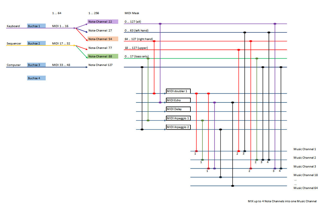
Blockschaltbild einer MIDI-Signalverarbeitung
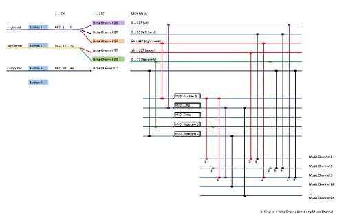
Keyboard Buchse 1 MIDI 1 ... 16 1 ... 64 MIDI Mask 0 ... 127 (all) Note-Channel 22 Sequencer Buchse 2 MIDI 17 ... 32 1 ... 256 Note-Channel 27 Note-Channel 54 64 ... 127 (right hand) Computer Buchse 3 MIDI 33 ... 48 0 ...
in „16 UARTs für MIDI“ · Mikrocontroller und Digitale Elektronik · · Diagramme
-
PDF
c64.pdf
. . . . . . . . . . . . . . . . . . . . . . . . . . . . . . . . . . . . . .16 . . . . . . . . 13 MidiSlave Hauptmenu˜. . . . . . . . . . . . . . . . . . . . . . . . . . . . . . . . . . . . . . . . . .18 . . . . . . 14 MidiSlave Midi-Einstellungen . . . . . . . . . . . . . . . . . . . . . . . . . . .
in „C64 SID mit Arduino Duemilanove ansteuern (korrigierte Version)“ · Mikrocontroller und Digitale Elektronik ·
-
PDF
Reloop_Elite_Serato_DJ_Pro_Quick-Start_Guide.pdf
mode 1. In this mode, you can assign pads 1-8 to different functions inside Serato DJ Pro, using the MIDI mapping feature, and save it as your own pad mode. Refer to the MIDI Mapping with Serato DJ Pro article, for more information on how to map MIDI functions. • USER mode 2: Press the ‘SAMPLER’ mode button
in „c't 11/2007 - LabView 6.1 als kostenlose Vollversion (*)“ · PC Hard- und Software ·
-
Datei
Synth.asm
rstate, 8, s8 LongJump rstate, 9, s9 rjmp loop2 ;Keyaus state s0: ;Poll for keyon ;2 = Byte0 vom Midi (On/Off) ;1 = Byte1 vom Midi (Taste) LoadMidiByteX 3, rmp CompSetEQ rmp, 0x90, rstate, 1 ;else... rjmp keyoff ;Zwischenstate ;um playkey zu laden s1: ;lade Taste1 aus sram LoadMidiByteX 2, rbuf ld rkey1
in „Attiny2313 Timer16 Bit, Normal Mode, unsauber“ · Mikrocontroller und Digitale Elektronik ·
-
PDF
korg_sp-250.pdf
in order and check if abnormal noise does not come from speakers (Click Noise, Hum Noise and etc) <MIDI Synchronization check> Connect from SP250 MIDI OUT to MIDI IN of another MIDI unit.by using MIDI cable. Play the SP-250 and check if the MIDI unit moves correctly. <Demo Performance check and Master
in „Korg SP-250 lässt sich nicht mehr anschalten / Elko ausgelaufen?“ · Analoge Elektronik und Schaltungstechnik ·
-
PDF
korg_sp-250_ServiceManual.pdf
in order and check if abnormal noise does not come from speakers (Click Noise, Hum Noise and etc) <MIDI Synchronization check> Connect from SP250 MIDI OUT to MIDI IN of another MIDI unit.by using MIDI cable. Play the SP-250 and check if the MIDI unit moves correctly. <Demo Performance check and Master
in „Korg SP-250 e-Piano hängt sich auf“ · Analoge Elektronik und Schaltungstechnik ·
-
PDF
korg_sp-250.pdf
in order and check if abnormal noise does not come from speakers (Click Noise, Hum Noise and etc) <MIDI Synchronization check> Connect from SP250 MIDI OUT to MIDI IN of another MIDI unit.by using MIDI cable. Play the SP-250 and check if the MIDI unit moves correctly. <Demo Performance check and Master
in „E-Piano Korg SP-250 rechter Lautsprecher rauscht und kratzt“ · Analoge Elektronik und Schaltungstechnik ·
-
PDF
korg_sp-250.pdf
in order and check if abnormal noise does not come from speakers (Click Noise, Hum Noise and etc) <MIDI Synchronization check> Connect from SP250 MIDI OUT to MIDI IN of another MIDI unit.by using MIDI cable. Play the SP-250 and check if the MIDI unit moves correctly. <Demo Performance check and Master
in „Korg SP-250 schaltet Register um“ · Analoge Elektronik und Schaltungstechnik ·
-
PDF
Notenerzeugung_Folie_6-13.pdf
Einfach über serielle Schnittstelle (UART) realisierbar Einfache Befehlsstrukturen, z.B.: http://www.midi.org/techspecs/midimessages.php technische universität fakultät für © m. engel, p. marwedel, dortmund informatik informatik 12, 2011 ▯- 15 - MIDI Input Erweiterung des Rechteck-Synthesizers um MIDI in • Austausch des Notengenerators durch UART • UART empfängt MIDI-Nachrichten (Note on/off) • Setzt „key“ 0kkkkkkk-Parameter in „note“ um • Ignoriert „velocity“-Parameter Tiefpassfilter 1,6kΩ clk Ton- (100 MHz) Generator Div note links audioL 10nF 31250 Hz MIDI Ton
in „Pinbelegung Notenerzeugung mit FPGA (Altera DE2-115) mit VHDL Code“ · FPGA, VHDL & Co. ·
-
Datei
ADSR_Funktion.c
ADSR-Hüllkurvensteuerung // // Timer2 Interruptroutine (alle 1msec) // // tasten_flag = 0 wenn kein Midi Notenwert empfangen wurde // tasten_flag1 = 1 wenn "Midi-Note On" empfange wurde // tasten_flag1 = 2 wenn "Midi-Note Off" empfangen wurde // adsr_phase1 = 1-3 ADSR-Phasen //-------------------------
-
PDF
Victron_MEGAFuse_Sicherungen_Datenblatt.pdf
MIDI, MEGAand ANL fuses, and fuse holders www.victronenergy.com MIDI fuses 32V Appr. voltage drop Cold resistance MIDIfuse100A/32V 60mV 0,45mΩ MIDIfuse150A/32V 80mV 0,30mΩ Fuse holder for MIDI fuse MIDI-fuse200A/32V 80mV 0,25mΩ MIDI fuses 58V Appr. voltage drop Cold resistance MIDIfuse60A/58V 70mV 0,9mΩ MIDIfuse100A/58V 70mV 0,45mΩ MIDI fuse MEGA fuses 32V Appr. voltage drop Cold resistance MEGA fuse60A/32V 120mV 1,5mΩ MEGA fuse80A
in „Absicherung einer autarken Stromversorgung (Camper)“ · Fahrzeugelektronik ·
-
PDF
TSynth_Schematic_V1_1.pdf
LED Retrig_Btn MIDI In TRS Jack (Opt.) 1k5 2 Tempo_LED SW5 Settings S 3 6 MIDI_IN Menu_Btn R D4 5 D5 R8 SW6 Save T 1N4148WS R9 Retrig LED 1k5 Save_Btn GND Retrig_LED 4k7 SW7 Back Back_Btn GND This is an optional MIDI TRS
in „Electrotechnic T-Synth DIY Synthesizer - Platinenanalyse“ · Mikrocontroller und Digitale Elektronik ·
-
Datei
Shruthi2_102.txt
type // note on --------------------------------------------------- case midi::NoteOn: note = MIDI.getData1(); velocity = MIDI.getData2(); set_Voice_on(note); break; // note off -------------------------------------------------- case midi::NoteOff: note = MIDI.getData1(); velocity = MIDI.getData2(); set_Voice_off(note); break; // Contrl: PitchBend ----------------------------------------- case midi::PitchBend: pitch_bnd = (MIDI.getData2() << 7) + MIDI.getData1(); pitch_bnd = (pitch_bnd
in „Teensy Synth "Shruthi 2"“ · Mikrocontroller und Digitale Elektronik ·
-
Datei
glcd_ui_cfg.h
GVI_DAP_MUTE 7 #define GVI_DAP_USAGE 8 #define GVI_DISP_CONTR 10 #define GVI_DISP_BRIGHT 11 #define GVI_MIDI_CHAN 15 #define GVI_MIDI_ACT 16 #define GVI_MIDI_GATE 17 #define GVI_MIDI_TEMPO 18 #define GVI_VOLUME_LEVEL_LEFT 32 #define GVI_VOLUME_LEVEL_RIGHT 33 #define GVI_DELAY_INPUT_LEVEL 32 #define GVI_DELAY_OUTPUT_LEVEL
in „Konzeptphase für Hobbyprojekt“ · Mikrocontroller und Digitale Elektronik ·
-
Datei
main.c
#include "avr/io.h" #include "spi.h" #include "midi.h" uint8_t current = 1; uint8_t cc_nums[4][8] = {{2,3,10,11,12,13,0,1}, {6,7,14,15,17,16,4,5}, {102,103,8,9,18,19,100,101}, {110,111,104,105,106,107,108,109}}; uint8_t last_val = 0; uint8_t buffer[128]; void update_changes(uint8_t cc, uint8_t val) { //if(val != buffer[cc]) { midi_send_cc(cc, val); midi_send_cc(cc, buffer[cc]); midi_send_cc(cc, val != buffer[cc]); buffer[cc] = val; } } void next_readout() { PORTD |= (1<<PD3); // ALE -> High PORTD |= (1<<PD2); // START -> High
in „ATmega8 Probleme mit Vergleichen“ · Mikrocontroller und Digitale Elektronik ·
-
Datei
midi.asm
#include 8051.H .org 0000H clr TR1; Timer 1 stoppen, warum auch immer mov PCON,#10000000b; Baudratenverdopplung an mov TMOD,#00100010b; beide Zaehler 8bit auto nachl einer auch wuerde reichen mov TH1,#0feh; #0feh-28800Baud bei 11,0592MHz, 31250 bei 12MHz setb TR1; starte Timer 1 mov SCON,#01000000b; Mode 1 setb TI; bereit zur Uebertragung main mov a,#00 next mov P1,a; das am unteren Schleifenende negierte a auf den Port mov r4,a; das a zwischenspeichern mov a,#90h; noteon ch0 acall tx mov a,#3ch; middle c acall tx mov a,#40h; velocity acall tx mov r1,#3 ;ab hier Verzoegerungsschleife loop0 mov
in „MIDI, 8051 und asm; sehr mysteriöses Problem Bitte helft mi“ · Mikrocontroller und Digitale Elektronik ·
-
PDF
Midi.pdf
Lötfahnen 2 LED5 10k CON2 1000µF C2 100µF R16 GND 29.10.2014 01:26:55 C:\Users\Anwender\Documents\eagle\Midi-Zerrer\Switch - Kopie.sch (Sheet: 1/1)
in „Probleme mit Atmega16 beim auschalten der Lötstation“ · Mikrocontroller und Digitale Elektronik ·
-
PDF
-
 Bild
Bild
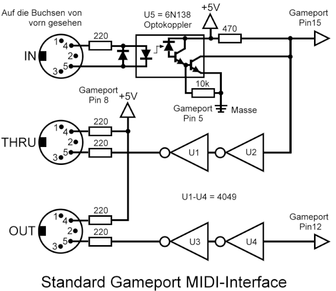
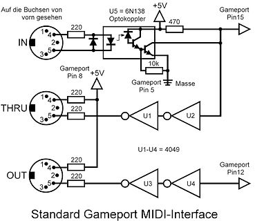
Schaltplan eines Standard Gameport MIDI-Interface
Pin 5, Masse, U1-U4 = 4049, OUT, 1, 2, 3, 4, 5, 220, 220, U3, U4, Gameport Pin12, Standard Gameport MIDI-Interface
in „MIDI -> UART Bridge“ · Mikrocontroller und Digitale Elektronik · · Schaltpläne
-
 Bild
Bild
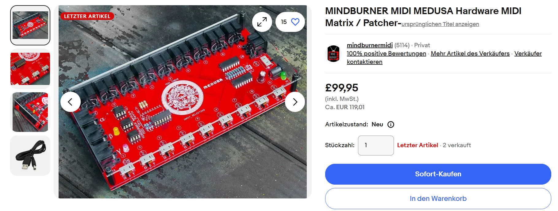
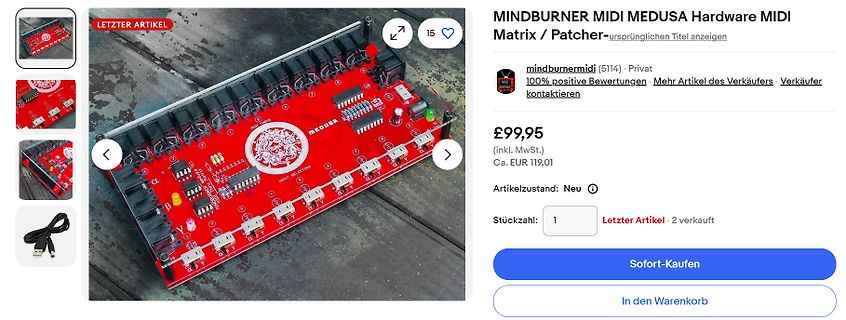
Mindburner MIDI Medusa Hardware MIDI Matrix
LETZTER ARTIKEL MINDBURNER MIDI MEDUSA Hardware MIDI Matrix / Patchermirusbinder midi (5114) · Privat 100% positive Bewertungen · Mehr Artikel des Verkäufers · Verkäufer kontaktieren £99,95 (inkl. MwSt.) Ca. EUR 119,01 Artikelzustand: Neu Stückzahl: 1 Letzter Artikel · 2 verkauft Sofort-Kaufen In den Warenkorb MEDUSA MIDI INPUT BELLS 1016
in „16 UARTs für MIDI“ · Mikrocontroller und Digitale Elektronik · · Screenshots
-
Datei
modules.txt
0xffffffffc0e2d000 snd_pcm_dmaengine 16384 1 snd_soc_core, Live 0xffffffffc0eed000 snd_rawmidi 49152 1 snd_seq_midi, Live 0xffffffffc0e11000 snd_seq 77824 2 snd_seq_midi,snd_seq_midi_event, Live 0xffffffffc0e88000 snd_seq_device 16384 3 snd_seq_midi,snd_seq,snd_rawmidi, Live 0xffffffffc0bb6000 snd_seq_midi 20480 0 - Live 0xffffffffc0e1e000 snd_seq_midi_event 16384 1 snd_seq_midi, Live 0xffffffffc0dad000 snd_soc_acpi 16384 2 snd_sof_intel_hda_common,snd_soc_acpi_intel_match, Live 0xffffffffc0f4c000 snd_soc_acpi_intel_match 61440 2 snd_sof_pci_intel_tgl
in „Wildgewordener Bildschirmschoner?“ · PC Hard- und Software ·
-
PDF
xone92.pdf
3 4 4 FILTER_R +5V 5 5 6 6 -5V R25 1 FILTER_DC_S 7 7 8 8 FILTER1_DC 9 9 10 10 -3.7 VREF_C 2K2 C33 MIDI_FILT1 11 11 12 12 FILTER_XFADER +15V 13 13 14 14 -15V 1/63 FILT1_MIDI 15 16 +5V 15 16 FILTER R95 VCF_MIDI 0R0 0805 AI1 AI2 LP1 LP2 LP3 LP4 LP5 FID1 FID2 AI3 AI4 LP1_1 LP2_1 LP3_1 LP4_1 LP5_1 FID3 FID4
in „Fehlersuche in DJ-Mixer (Allen & Heath Xone:92)“ · Analoge Elektronik und Schaltungstechnik ·
-
Datei
MidiTest.asm
clr Anzahl ; *** Midi-UART anschalten *** ldi Temp1, 0b10010000 ; Receiver anschalten und Interrupt erlauben out UCR, Temp1 ; und weg damit... ; *** Hauptschleife *** main: ; irgendwas... rjmp main ; *** UART Empfangs-Routine *** midi: push Temp1 in Temp1, SREG ; Status-Register sichern push Temp1 in Temp1, UDR ; Empfangenes Byte holen cpi Temp1, 248 ; Clock? breq m_out ; Erstmal unwichtig... cpi Temp1, 250 ; Start? breq m_out ;
in „AVR & Midi Probleme“ · Mikrocontroller und Digitale Elektronik ·
-
Datei
SDCARD.c
== 0) { DCOs(); } } //----------------------------------------------------------------- // check midi-buffer and play note //----------------------------------------------------------------- if(mididata_avail() == 1) { midi_handle(); // handle midi-data } //------------------------------------------
in „MMC SD library FAT16 FAT32 read write“ · Projekte & Code ·
-
PDF
VBus_Protokoll_allgemein.pdf
........................................................................................ 3 1.3.9. MIDI Pro...................................................................................................................................... 3 1.3.10. DeltaSol M........................................
in „solarsteuerung mit atmega8 auslesen“ · Mikrocontroller und Digitale Elektronik ·
-
PDF
vs1033d.pdf
VS1033 D VS1033d VS1033 - MP3/AAC/WMA/MIDI AUDIO CODEC Features Description † Decodes MPEG 1 & 2 audio layer III (CBR VS1033 is a single-chip MP3/AAC/WMA/MIDI +VBR +ABR); layers I & II optional; MPEG4/2 AAC-LC-2.0.0.0 (+PNS); audio decoder and
in „Layout dringend“ · Platinen ·
-
 Bild
Bild
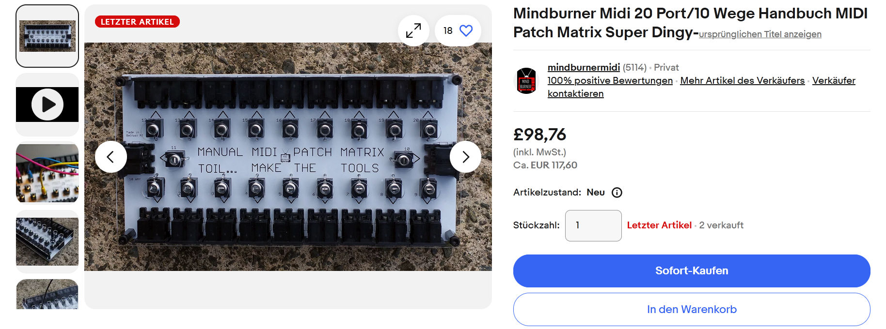
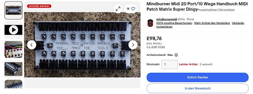
Screenshot eines Verkaufsangebots für ein MIDI Patch Matrix Modul
LETZTER ARTIKEL Mindburner Midi 20 Port/10 Wege Handbuch MIDI Patch Matrix Super Dingy... ursprünglichen Titel anzeigen mindburnermidi (5114) Privat 100% positive Bewertungen Mehr Artikel des Verkäufers Verkäufer kontaktieren £98,76
in „16 UARTs für MIDI“ · Mikrocontroller und Digitale Elektronik · · Screenshots
-
 Bild
Bild
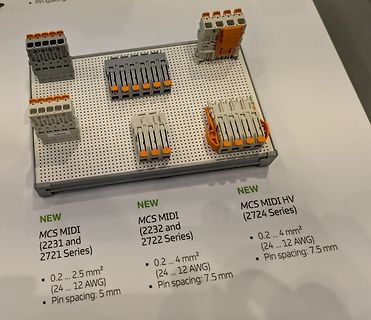
Verschiedene MCS MIDI Steckverbinder auf Displaytafel
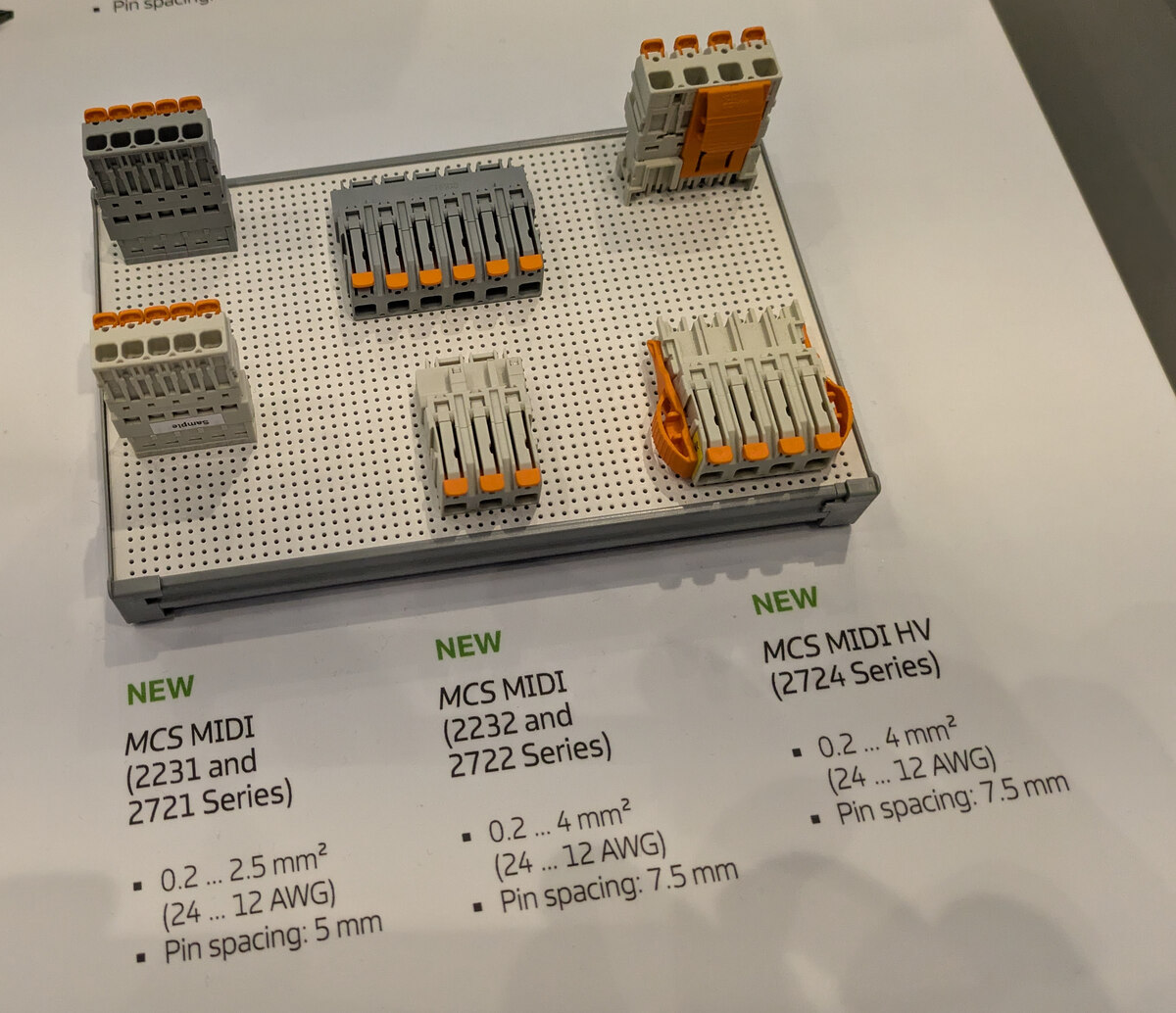
NEW MCS MIDI (2231 and 2721 Series) 0.2 ... 2.5 mm² (24 ... 12 AWG) Pin spacing: 5 mm NEW MCS MIDI (2232 and 2722 Series) 0.2 ... 4 mm² (24 ... 12 AWG) Pin spacing: 7.5 mm NEW MCS MIDI HV (2724 Series) 0.2 ...
in „EmbeddedWorld 2026, Catch-All – Bauteile, Stromversorgungen, Meshnetze uvam“ · Mikrocontroller und Digitale Elektronik · · Fotos
-
 Bild
Bild
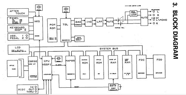
Blockschaltbild eines elektronischen Geräts
MONO O R MASTER VOL. SYSTEM BUS CPU V55PI CBR1/F MAP55 ROM STYLE ROM BACK UP RAM WORK RAM FDC FDD MIDI IN MIDI OUT MIDI THRU RESET BATTERY BACK UP
in „Keyboard Korg i3 alte Version Verzerrung“ · Mikrocontroller und Digitale Elektronik · · Diagramme
-
 Bild
Bild
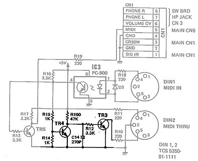
Schaltplan einer MIDI-Schnittstelle
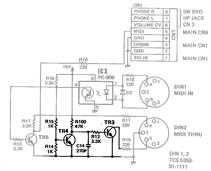
CN1 PHONE R 8 PHONE L 7 VOLUME CV 6 MIDI 5 GND 4 CRSSW 3 GND 2 SIG IN 1 MAIN CN1 MAIN CN9 IC3 PC-900 R19 220 R18 220 D3 DIN1 MIDI IN R16 3.3K R17 3.3K R15 1K R13 3.3K TR5 TR4 TR3 R100 47K R12 3.3K R14 1K C14 270P R11 220 R10 220 DIN2 MIDI
in „IC für MIDI Ausgang“ · Mikrocontroller und Digitale Elektronik · · Schaltpläne
-
 Bild
Bild
Schaltplan Arduino MIDI In und Out
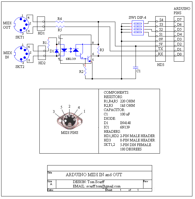
MIDI OUT, R4, 2, 5, SKT1, HD1, R5, 1, 4, 2, 3, 5, MIDI IN, R1, D1, 4, 2, 3, 5, SKT2, HD2, 6N139, 8, 6, 3, 4, 7, R2, 5, C1, SW1 DIP-4, S4, D7, S3, D6, S2, D5, S1, D4, 0V, D3, 5V, D2, TX, D1, RX, D0, HD3,
in „MIDI -> UART Bridge“ · Mikrocontroller und Digitale Elektronik · · Schaltpläne