pitschu schrieb:
> sync lock and H

Waldemar schrieb:
> zoe schrieb:
>> Waldemar schrieb:
>> Maybe you have to Power the hdmi2av converter with USB?
>>
>> yeah I have powered it already. i think it's some kind of malfunction
>> because it's very hot, is there anyway for me to check with
>> oscilloscope?
>
> Check your converter with an old TV which has an AV Input

thanks both of you
I think that was problem
and not because my converter.
I have connected the converter with an HDMI signal from my second HDMI
port on the VGA (my computer) and set the desktop mode to duplicate and
extend
may be that was the problem. I will try it again and hope you will be
here to help me
thanks again
hello, do you think the resistor and câpcitors between in put and in put
chanel on the chip is the problem of video signal?
No, the resistors are needed to simulate an input impedance of nearly 75
ohm, the capacitor is needed do decouple the input regarding DC voltage
from the chip input. You should not remove them.
pitschu schrieb:
> No, the resistors are needed to simulate an input impedance of
> nearly 75
> ohm, the capacitor is needed do decouple the input regarding DC voltage
> from the chip input. You should not remove them.

thank you. how can i test the board tvp5150 if it has problems. i think
the converter is fine because the computer regconized it
To use the board 'out of the box' with the software published here you
need a video signal which is compatible to one of the supported video
standards (look at the datasheet). The mode should be detected
automatically but it's only tested with the European PAL 50Hz standard.
Look at the logged status registers of the TVP, especially Status Reg 5
shows the actual video standard which was detected.If your signal cannot
be decoded you could try to change the initial settings for various
registers. May be the documentation of your hdmi2av converter gives some
hints of the output signal (Vpp + coding).
my HDMI2AV converter is the 1080p only. was that the problem?
the hdmi2av converts FROM hdmi 1080p to another AV format. This format
should be supported by the ambilight processor. Do you have an
osziloscope to check the output of the hdmi2av?
oh god. i think my converter not support 1080p input
pitschu schrieb:
> the hdmi2av converts FROM hdmi 1080p to another AV format. This
> format should be supported by the ambilight processor. Do you have an
> osziloscope to check the output of the hdmi2av?

I have and when i connnect the red wire of oscilloscope to the output. i
saw like sin wave. after that. i connect the black wire to gnd. it
straight out
Angehängte Dateien:
-

Screenshot__410_.png
80 KB
I've check and buy a new converter. so the converter is not the problems
can you tell me is there any factor cause no signal to TVP5150AM1??
(capacitor, resistor?) the comunicate between 5150AM1 and stm32 board is
ok
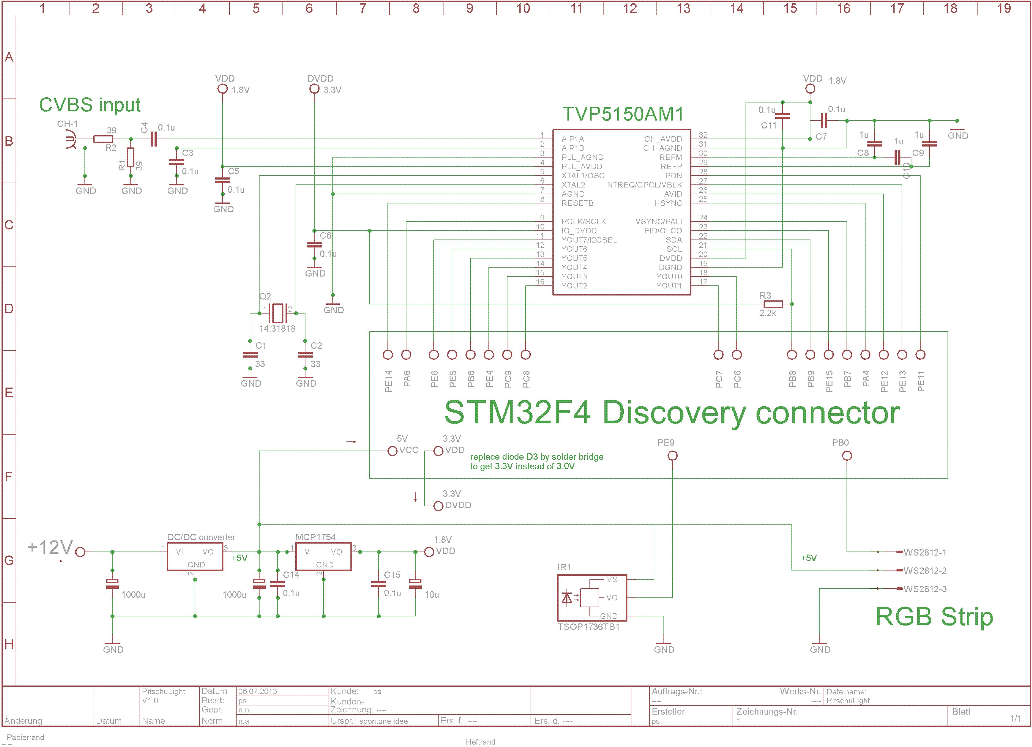
I got exactly this problem like Pat Wat has before, no video signal
can anyone check is there anything fail in this schematic and PCB?
(atached)
I'm trying to replace 39 ohms with exactly 37.4 ohm and see what happens
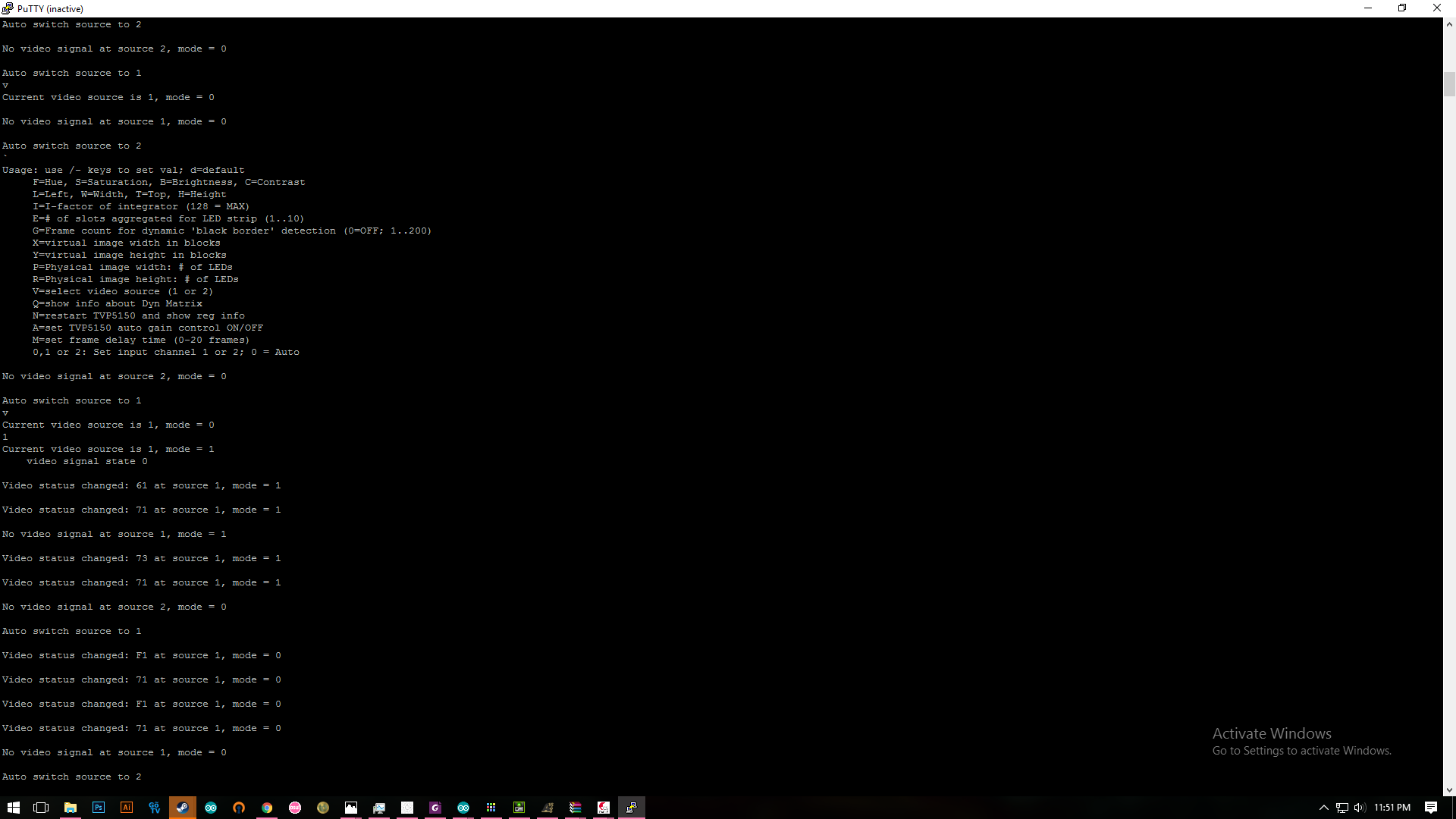
zoe schrieb:
> I'm trying to replace 39 ohms with exactly 37.4 ohm and see what
> happens

I'm sure that this will not solve your problem. Can you measure the
video signal directly at he input pin of the TVP and post an screen
image here? Your log shows, that the video status changes from 61, 71
and sometime 73. This means that no sync could be detected.
The file formats in your rar file are not usable for me. Can you make
PDF files of the schematic? Especially the TVP input and connection to
the STM32 are important.
pitschu schrieb:
> zoe schrieb:
> I'm trying to replace 39 ohms with exactly 37.4 ohm and see what happens
>
> I'm sure that this will not solve your problem. Can you measure the
> video signal directly at he input pin of the TVP and post an screen
> image here? Your log shows, that the video status changes from 61, 71
> and sometime 73. This means that no sync could be detected.

you want me to put the video signal directly to tvp5150 video input pin?
bypass the resistor and capacitor?
im getting an 8ch logic analyzer and will post the screen shot
thanks
Zoe schrieb:
> im getting an 8ch logic analyzer and will post the screen shot
> thanks

No, simply feed the video signal into the board (including the resistors
and capacitor) and measure the resulting signal at the input pin of the
TVP. You cannot use a logic analyzer for that because it's a analog
signal. A logic analyzer can only measure digital signals.
Angehängte Dateien:
-

IMG_2700.JPG
240 KB
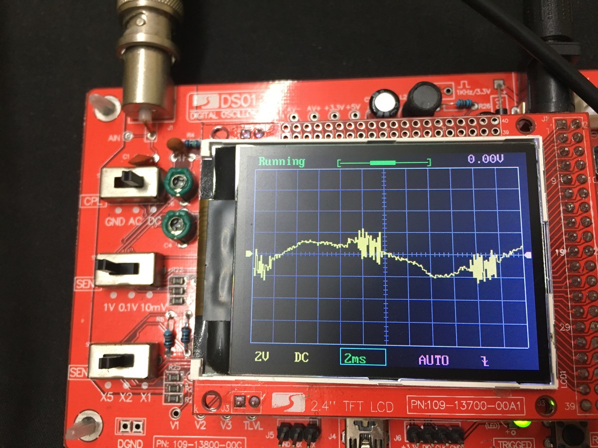
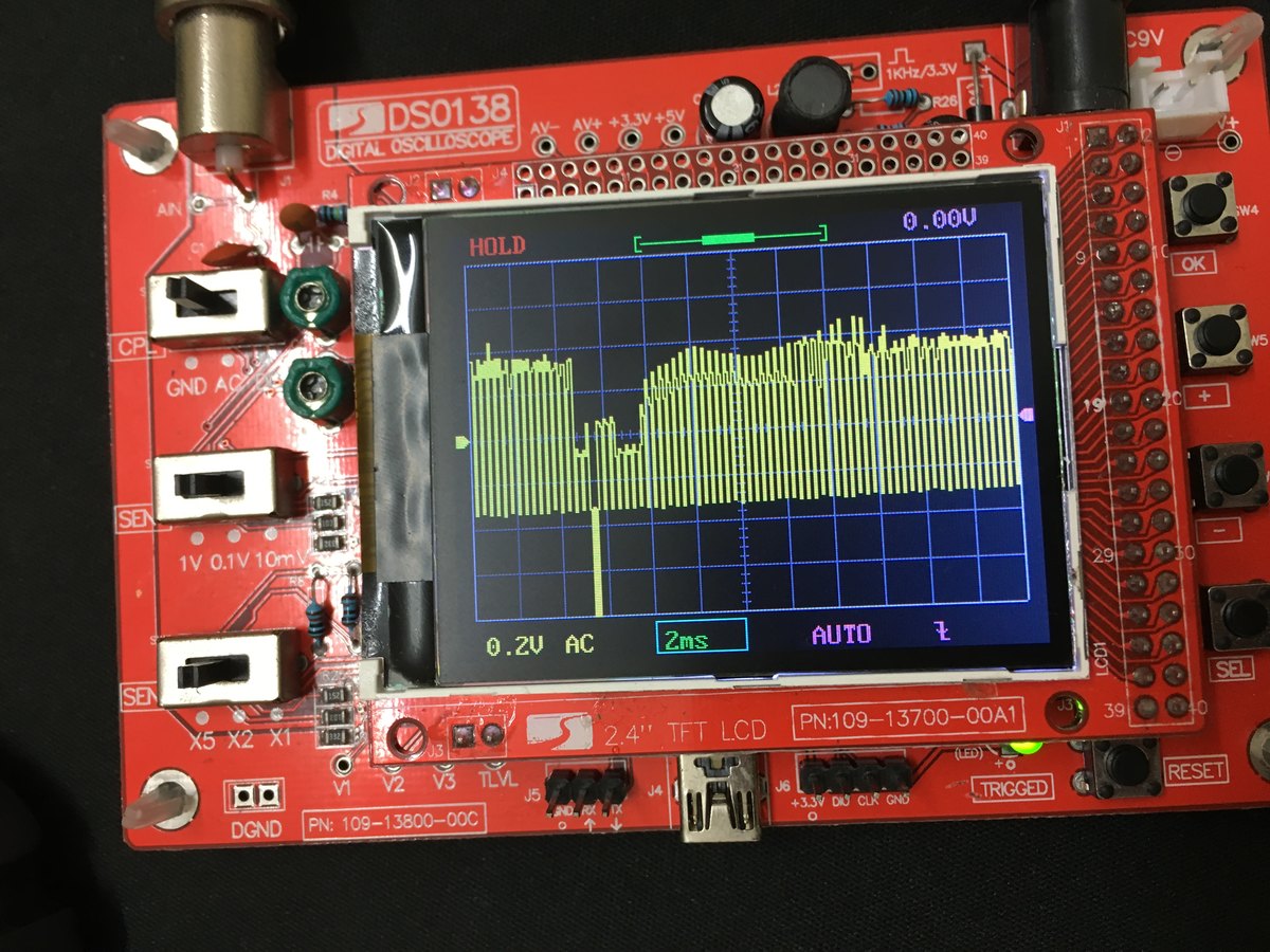
this is when i only connect the red wire of ócilloscope to the input pin
chanel 1 of tvp5150( the strange is it showed the same when connect to
chanel 2) so both no signal
Angehängte Dateien:
-

IMG_2701.JPG
240 KB
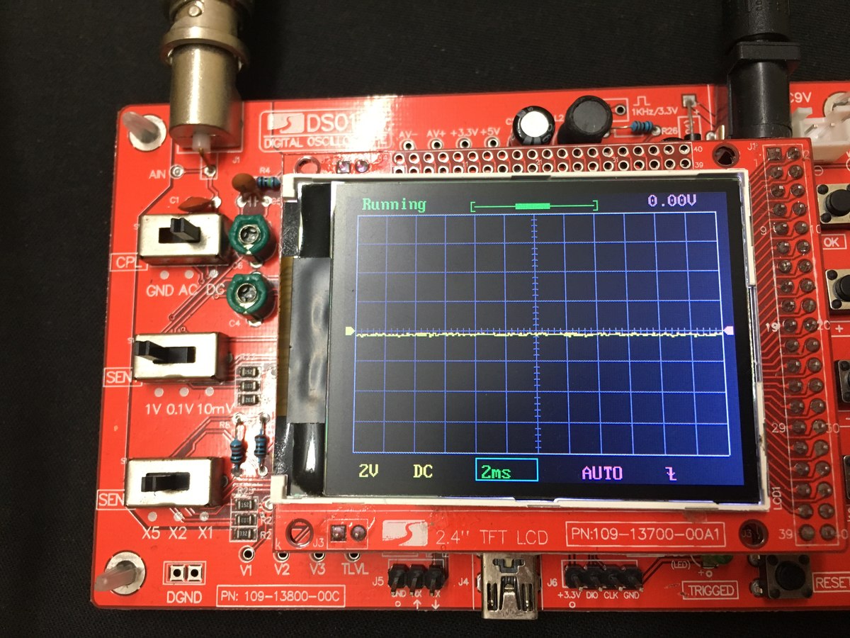
and this when i connect the black wire of oscilloscope and the red to
AGND and input chanel on chip
Zoe schrieb:
> and this when i connect the black wire of oscilloscope and the red
> to
> AGND and input chanel on chip

You have to measure always with connected GND. This means you have no
signal on your AL-Board. Measure the output (yellow chinch) of your
hdmi2av converter
Angehängte Dateien:
-

IMG_2703.JPG
230 KB
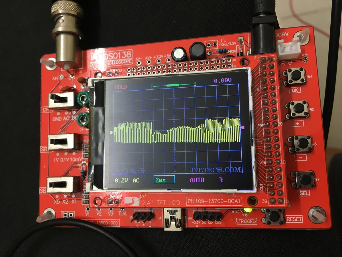
this is when I power up the converter with usb port
black wire to AGND
red wire to input chanel
(actualy the converter no need power support)
Angehängte Dateien:
-

IMG_2704.JPG
240 KB
and this is from yeallow chinch (disconnected with the board)
( i changed the voltage of the oscilloscope)
We can not open your schematic files, please post a PDF of it, because
the issue is on your board....

The FBAS-Signal of your converter looks fine
Waldemar schrieb:
> We can not open your schematic files, please post a PDF of it,
> because the issue is on your board....
>
> The FBAS-Signal of your converter looks fine

ok bro
here is the pdf. if you need anything i will convert
what if my TVp5150 chip malfunction??
I got it from china,
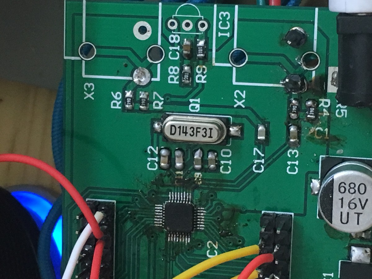
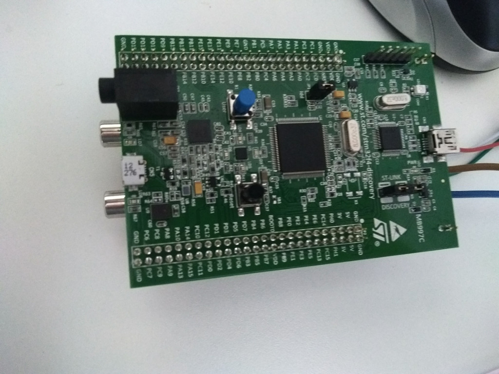
I'm not sure whether you soldered the TVP right. It seems that you
connected the input signals to pins 17 + 18 instead of 1 + 2. But I
can't really check it with your picture (could you please mark the pin 1
on the picture).
Does the crystal 143F3I really have 14.31818 MHz?
Angehängte Dateien:
-

dot.png
410 KB
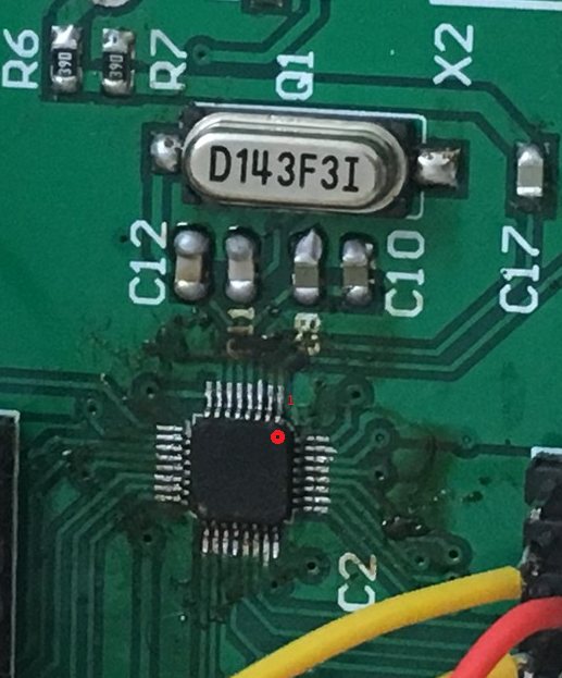
I will check the crystall again
I think the tvp5150 is soldered right because it respond to the stm32
when i press N in putty. it reset and report things about device id
..etc
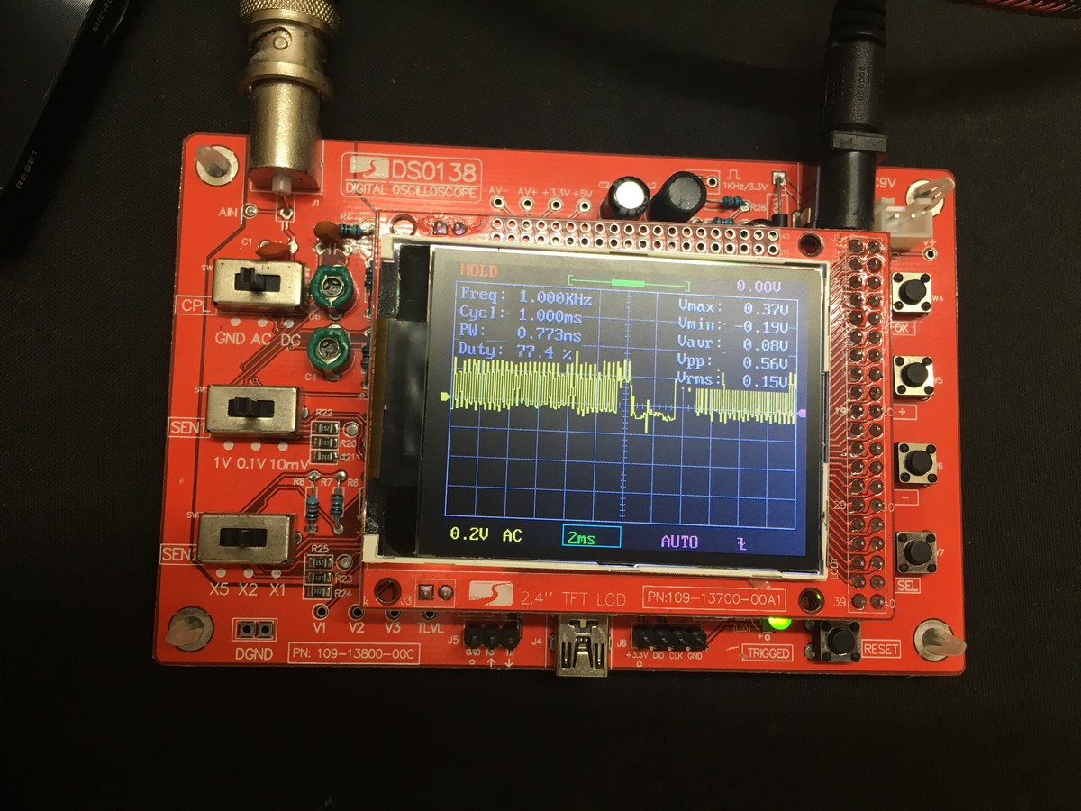
Yes, you are right, the I2C bus seems to be working. But the signal on
pins 1 or 2 looks wrong on your scope screenshot. It should look exactly
like the signal out of the chinch socket (second screen shot) with only
half of the amplitude. Maybe you damaged the TVP chip.
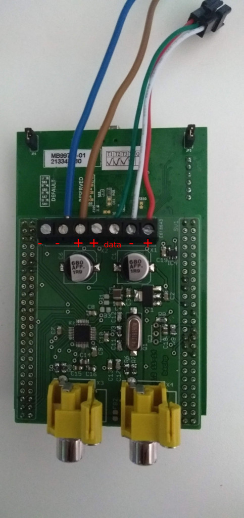
strange... if you can measure a video signal on your converter, then you
should measure a signal at PIN1 / PIN2 from TVP if the converter is
connected to the board. maybe check your wiring on board with multimeter
to capacitor C13 and from C13 to Pin1 of TVP and also the same for
INPUT2
Angehängte Dateien:
-

IMG_2703.JPG
230 KB

Waldemar schrieb:
> strange... if you can measure a video signal on your converter,
> then you should measure a signal at PIN1 / PIN2 from TVP if the
> converter is connected to the board. maybe check your wiring on board
> with multimeter to capacitor C13 and from C13 to Pin1 of TVP and also
> the same for INPUT2

yeah i have measured it and it show like this. just a little bit lower
than the original
output from yellow chinch on converter
it's only half because 2 39 ohms resistor reduce the voltage under 0.78
volts, right?
That's right, but the peaks to GND are missing. These peaks (you should
see them at least every 20ms with your 'scope') are the X/Y sync signals
are are important for correct video detection. The status log shows,
that the sync signals are missing and the scope shows, that it's true
:-)
Please check the 1.8V and 3.3V supply of the TVP.
Zoe schrieb:
> yeah i have measured it and it show like this. just a little bit lower
> than the original
> output from yellow chinch on converter

OK, sorry i misunderstood you. I thought the measurement on the TVP-Pin
was in Post Beitrag "Re: Ambilight mit STM32F4discovery und TVP5150AM1"

First of all, i don't see any FBs on your Board (photos), second I would
bridge all FBs (with a wire, solder-bridge) until the board has full
functionality and check the supply voltages with oscilloscope
Angehängte Dateien:
-

IMG_2707.JPG
230 KB
this picture is when I soldered all FBs with solder bridge, the signal
from AGND and input chanel 1,
I think my TVP chip was gone, i will try to replace it and check again
the 1.8 voltage supply is 1.69 volt measured
the 3.3 is 3.14
Angehängte Dateien:
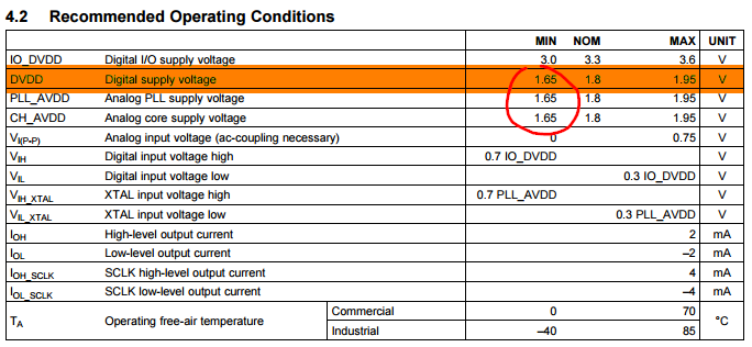
zoe schrieb:
> the 1.8 voltage supply is 1.69 volt measured
> the 3.3 is 3.14

not good... but i don't know that this coases the problems

Datasheet says min 1,65V. Maybe you have some error in your measurement
and then you get in trouble

Is the voltage regulator getting hot? Maybe your TVP is bad and draining
to much current, so this will cause the lower voltage on 1,8V rail

have you looked with your oscilloscope: are the voltages stable?
Waldemar schrieb:
> zoe schrieb:
> the 1.8 voltage supply is 1.69 volt measured
> the 3.3 is 3.14
>
> not good... but i don't know that this coases the problems
>
> Datasheet says min 1,65V. Maybe you have some error in your measurement
> and then you get in trouble
>
> Is the voltage regulator getting hot? Maybe your TVP is bad and draining
> to much current, so this will cause the lower voltage on 1,8V rail
>
> have you looked with your oscilloscope: are the voltages stable?

the oscillo show all the voltage not stable. i dont know why, it show
min max and average. 1.69 is average, and 3.14 too
the tvp 5150 is normal. no hot, im ordering 10 more tvp to find out what
is the problem :D
Zoe schrieb:
> the tvp 5150 is normal. no hot, im ordering 10 more tvp to find
> out what
> is the problem :D

please post photos of your measurements of 1,8v and 3,3v supply where we
can see the instability of the voltage. i asked if the 1,8v regulator
(LM1117) is getting hot or not
and this is 1.8
i change the adapter and the 3.3 is 3.22
1.8 is 1.69 and nothing happen
https://youtu.be/lGX7lG6fv4U
Hallo Frank

Hättest Du noch eine Platine über?

Wer sonst noch eine abgeben möchte, gern auch bestückt - ich hätte
Interesse.

Viele Grüße
Jens
Hallo Jens,

vor etwas über einem Jahr habe ich mir von pitschu eine Bestückte
Platine incl. SW gekauft. Bin dann aber nicht dazu gekommen das Projekt
fertig zu stellen. Wenn Du willst kannst Du sie haben.

LG EDE
EDE schrieb:
> Wenn Du willst kannst Du sie haben.
>
> LG EDE

Hallo EDE

Zur weiteren Absprache melde Dich bitte mal unter ambilight -at-
ist-einmalig.de.

Viele Grüße
Jens
Hallo zusammen,
Wegen Umstieg auf original Philips und fehlender Zeit verkaufe ich meine
2 Sets Ambilight.

1. Set beinhaltet das STM32F4, das bestückte und getestete 555 Board,
HDMI Splitter, HMDI-> Analog Converter, 5V 5A Schaltnetzteil (Meanwell)
und 5m WS2812B (neu) 60 LEDs/m und Gehäuse.

2.Set beinhaltet das STM32F4, das bestückte und getestete 555 Board und
einen ALU-Profil U Rahmen mit darin verlegten WS2812B 60LEDs/m passend
für TV ab 42 Zoll (wurde bei 55 Zoll verwendet).

Bitte nur seriöse Angebote unterbreiten. Fotos kann ich bei Interesse
per Mail versenden.
Angehängte Dateien:
-

Screenshot__485_.png
2,4 MB
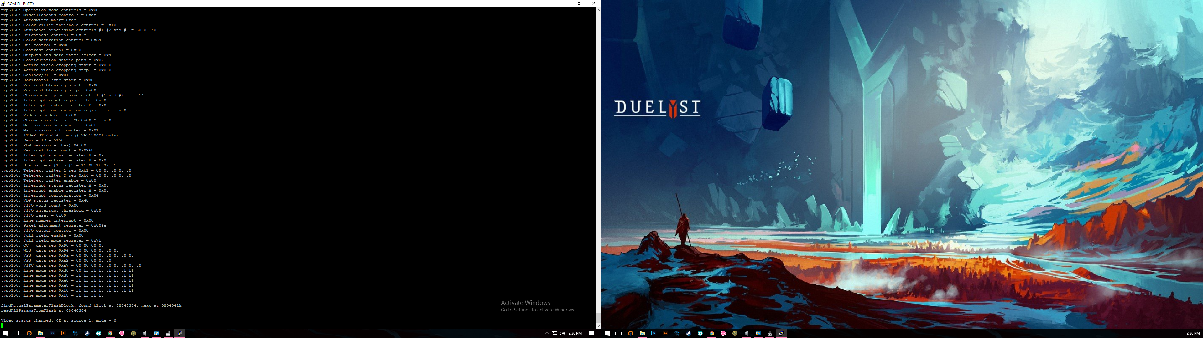
hello pitschu
after 1 busy month i got back to this board
change the 5150 AM1 chip vendor and got this like you said
status 0E
Angehängte Dateien:
-

Screenshot__487_.png
99 KB
the log lock 0E and nothing show out to the led.led is off
what is the problem here? the tvp board is working right? because the
video status is 0E
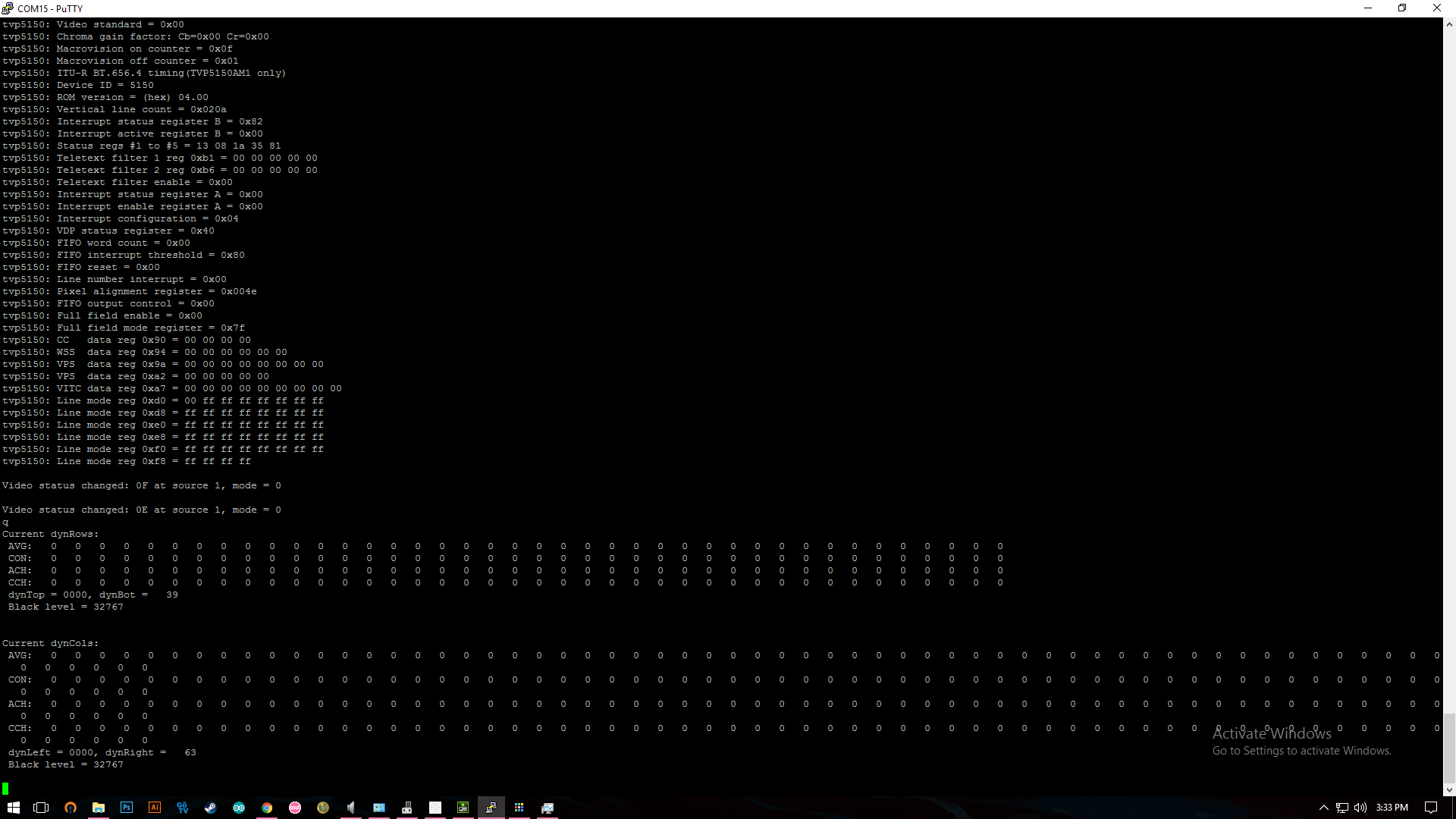
finally the led turn on and reacto to the screen but with the weird way
the green on the screen is the white, the color is not true and only
afte the log show
IR data: 0040, rep count: 20
Mood/Ambi mode switched to 02
IR data: 0040, rep count: 20
Mood/Ambi mode switched to 02
IR data: 0040, rep count: 20
Mood/Ambi mode switched to 02
IR data: 0040, rep count: 20
Mood/Ambi mode switched to 02
IR data: 0040, rep count: 1
Mood/Ambi mode switched to 01

the led turn on,
otherwise. it's off
help
ah yes it's happen when i press the button on stm32 board. then log show
ir data received and led turn on. the black is pure green (wrong color)
and it's not stable
this is the log
IR data: 0040, rep count: 1
Mood/Ambi mode switched to 01
q
Current dynRows:
 AVG:  89 107 111 115 112 114 105  96  96  96  97  95 102 100  96 103
83  94 12 160 137 153 152 152 153 157 138 129 29 130 131  76  91  96   0
0   0   0   0   0
 CON: 197 341 350 332 313 302 302 209 203 208 214 214 212 199 191 196
160 200 245 271 260 291 288 287 282 283 269 267 269 260 270 146  69 110
0   0   0   0   0   0
 ACH:   0  18   4   4  -3   2  -9  -9   0   0   1  -2   7  -2  -4   7
-20  11  30  36 -23  16  -1   0   1   4 -19  -9   0   1   1 -55  15   5
-96   0   0   0   0   0
 CCH:   0 144   9 -18 -19 -11   0 -93  -6   5   6   0  -2 -13  -8   5
-36  40  45  26 -11  31  -3  -1  -5   1 -14  -2   2  -9  10-124 -77
41-110   0   0   0   0   0
 dynTop = 0000, dynBot =   33
 Black level =    0


Current dynCols:
 AVG:  45  48  46  45  45  45  45  45  46  47  45  55  56  57  57  57
57  55  50  56  58  57  63  69  66  65  65  62  51  55  55  55  58  52
49  50  50  48  50  64  65  68  71  71  75  91  99 102 101 100  95  89
84  82  75  65  56  56  56  55  55  54  56  44
 CON: 140 153 154 150 145 147 146 153 160 179 185 229 281 290 296 302
300 288 292 298 295 295 283 323 316 325 317 307 249 286 303 315 321 256
248 254 252 225 246 323 330 335 339 341 358 396 395 404 404 400 391 381
347 336 303 258 199 204 207 202 204 190 174 118
 ACH:   0   3  -2  -1   0   0   0   0   1   1  -2  10   1   1   0   0
0  -2  -5   6   2  -1   6   6  -3  -1   0  -3 -11   4   0   0   3  -6
-3   1   0  -2   2  14   1   3   3   0   4  16   8   3  -1  -1  -5  -6
-5  -2  -7 -10  -9   0   0  -1   0  -1   2 -12
 CCH:   0  13   1  -4  -5   2  -1   7   7  19   6  44  52   9   6   6
-2 -12   4   6  -3   0 -12  40  -7   9  -8 -10 -58  37  17  12   6 -65
-8   6  -2 -27  21  77   7   5   4   2  17  38  -1   9   0  -4  -9 -10
-34 -11 -33 -45 -59   5   3  -5   2 -14 -16 -56
 dynLeft = 0000, dynRight =   63
 Black level =    0
aaaaaaaaaaaaaaaaaaaaaaaaaaaah yeasssssssssssss everything is working
now. just solder wrong pin E6 so all green color.
thank you all
Great project! Did you try "Embedded Synchro" mode with DCMI on
STM32F04? I think you used the "8-Bit 4:2:2 With Discrete Syncs" mode of
TVP5150, fed that to STM32 together with VSYNC / HSYNC lines, in
"External Synchro" mode.

This is exceptional property of TVP5150AM1 that it can strip out ITU-R
BT 656 embedded sync codes (SAV / EAV) out of data stream. DCMI does
support embedded sync – no VSYNC, HSYNC connections are required.
However – not in interlace mode! Only in progressive mode (8-bit).
That's my problem. I want to use ADV7280 because it allows component
input YPbPr, not only CVBS and S-Video. But it cannot strip out the
embedded codes SAV / EAV. It however allows interlace -> progressive
conversion – at cost of 54 MHz pixel clock (2x 27MHz). So I'll probably
be fine, will use "Embedded Synchro" with 54 MHz input (supported by
STM32F767). I'm just curious of your experience, because it's the first
post on the internet that successfully integrated video-decoder IC with
STM32 DCMI. Did you try embedded synchro mode with DCMI?
Hallo zusammen,
Wegen Umstieg auf original Philips und fehlender Zeit verkaufe ich meine
2 Sets Ambilight.

1. Set beinhaltet das STM32F4, das bestückte und getestete 555 Board,
HDMI Splitter, HMDI-> Analog Converter, 5V 5A Schaltnetzteil (Meanwell)
und 5m WS2812B (neu) 60 LEDs/m und Gehäuse.

2.Set beinhaltet das STM32F4, das bestückte und getestete 555 Board und
einen ALU-Profil U Rahmen mit darin verlegten WS2812B 60LEDs/m passend
für TV ab 42 Zoll (wurde bei 55 Zoll verwendet).

Bitte Angebote unterbreiten. Fotos kann ich bei Interesse
per Mail versenden.
Hallo. Beide Sets sind noch zu haben.

Ausserdem verkaufe ich noch einen
ANALOG DEVICE ADV7612 Dual Port, Xpressview, 225 MHz HDMI Receiver

http://www.analog.com/media/en/technical-documentation/data-sheets/ADV7612.pdf

NEU und unbenutzt.
I am trying to get data from tvp5150 and send it to LCD. I have
horizontal and vertical  synchronization problems. Seems like synhro
isn't generated properly (in right time) by TVP. Do you have any idea of
this?
Hallo,

ein großes Lob an alle, die zu diesem Projekt beigetragen haben, vor
allem an pitschu!
Habe das Projekt mit China-Bestellungen im Wert von unter 50 € pro
pitschulight umgesetzt. STM32-Board, PCB und LED-Stripes mit 60 LEDs/m
sind bereits eingerechnet. Die ersten beiden fertigen Boards
funktionieren tadellos.
Bevor die Fragen aufkommen: Ich möchte keine überschüssigen Teile und
auch keine fertigen Leiterplatten verkaufen. Musste bestimmt über 300 €
ausgegeben, um alle Teile für die ersten 5 pitschulights zu kaufen. PCBs
und Bauteile sind für insgesamt 10 Stück vorhanden, für die Bastelkiste
wird am Schluss auch noch was übrig bleiben. Ein einzelnes Exemplar kann
man sich also nicht für 50 € zusammenbauen.

Wenn Interesse besteht, kann ich die Artikel vom Auktionshaus mal
zusammenschreiben, das PCB Layout kann ich auch weitergeben. Allerdings
ist das Layout grottenschlecht, da zum Großteil vom Eagle Autorouter
übernommen.

Nun zu meinem eigentlichen Anliegen: Habe ein STM32-Board mit
STM32F407VET6 (512 kB Flash). Die hex-Datei aus dem Beitrag unten läuft,
ich kann aber keine Änderungen am Code vornehmen. Z.B. möchte ich die
IR-Codes ändern, da ich noch ein paar Wochen auf die Fernbedienung aus
der Anleitung warten muss. Kann bitte jemand den Quellcode für 512 kB
zur Verfügung stellen bzw. die nötigen Änderungen mitteilen? pitschu
vielleicht?

Bereits jetzt vielen Dank!

Michael

Peter S. schrieb:
> I just tried the HEX attached in this post on a brand new
> STM32F4dicso
> board. I made some changes for your CPU (only 512K flash). I'm sure it
> works and USART out is on PD8. Please use this HEX and tell what's
> happening.
>
> pitschu
Hallo Michael,

du musst 3 Dateien anpassen:
- Das Linkerscript unter ldscripts/mem.ld
- die Include-Datei flashparams.h
- Source-File flashparams.c

In mem.ld ist lediglich der FLASH size von 1024k auf 512k anzupassen.
Sicherheitshalber solltest du aber das Datenblatt checken, ob RAM sizes
evtl. auch anders sind.
In flashparams.h sind Anfang und Ende des Parameter-Pseudo-EEPROMs
verzeichent. Hier ist z.B. PARAM_FLASH_START von 0x080C0000 auf
0x08040000 zu ändern. Die anderen defines entsprechend auch.
Im source flashparams.c gibt es eine Stelle, an der der Parametervereich
im Flash gelöcht wird:
    FLASH_EraseSector(FLASH_Sector_10, VoltageRange_3)
    FLASH_EraseSector(FLASH_Sector_11, VoltageRange_3);
Statt Sector 10+11 müssen die Sektoren 6+7 gelöscht werden.

Damit sollte es gehen.
pitschu
hello pitschu, I've sent you an email. please check it
thanks :D
Angehängte Dateien:
-

uart.png
240 KB
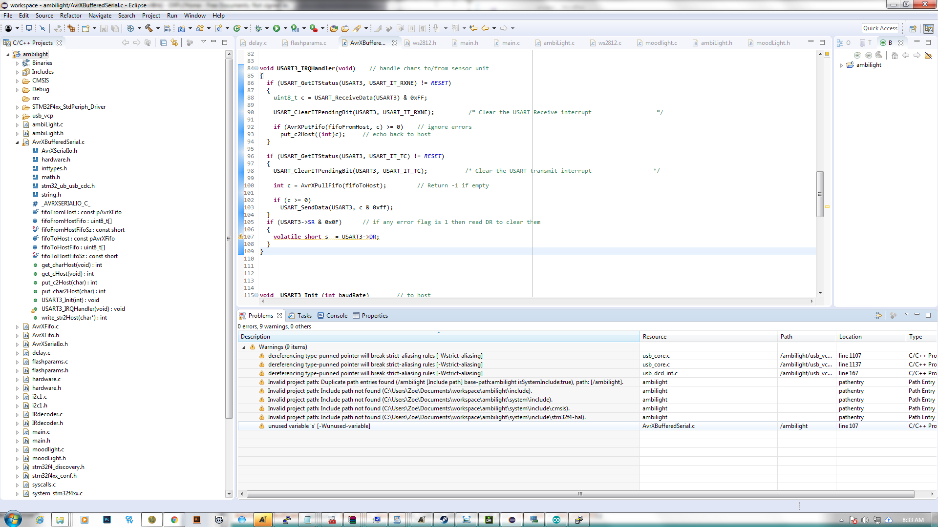
Hello everyone, It's me bothering you guys again
It's been a long time I haven't touch the Peter's project,
I decided to modify the code just to make the board works with Ws2811
12v LED (which has RBG order instead of RGB as ws2812B) I used custom
stm32f407vgt6 board and everything worked when flash Peter's original
code (terminal, LED mode, IR...)
after edit WS2812.h (to swap G and B value) everything worked fine
except USART3, no responding and transmitting  at all.
at first I thought it's because I edited the library but after revert to
original, USART3 still dead, I re-flashed peter's original Hex and
everything worked again
-I've never get USART3 (pd8 pd9) work on my own compiler,just Peter's
hex file worked
-anything to work with these warnings below?
Hallo,
ich habe ein Board hier liegen.


Leider bekomme ich nichts vom TVP5150. Ist der TVP5150 kaputt?:

Auto switch source to 1

No video signal at source 1, mode = 0

Auto switch source to 2

No video signal at source 2, mode = 0

Auto switch source to 1
tvp5150: Video input source selection #1 = 0x00
tvp5150: Analog channel controls = 0x00
tvp5150: Operation mode controls = 0x00
tvp5150: Miscellaneous controls = 0x00
tvp5150: Autoswitch mask= 0x00
tvp5150: Color killer threshold control = 0x00
tvp5150: Luminance processing controls #1 #2 and #3 = 00 00 00
tvp5150: Brightness control = 0x00
tvp5150: Color saturation control = 0x00
tvp5150: Hue control = 0x00
tvp5150: Contrast control = 0x00
tvp5150: Outputs and data rates select = 0x00
tvp5150: Configuration shared pins = 0x00
tvp5150: Active video cropping start = 0x0000
tvp5150: Active video cropping stop  = 0x0000
tvp5150: Genlock/RTC = 0x00
tvp5150: Horizontal sync start = 0x00
tvp5150: Vertical blanking start = 0x00
tvp5150: Vertical blanking stop = 0x00
tvp5150: Chrominance processing control #1 and #2 = 00 00
tvp5150: Interrupt reset register B = 0x00
tvp5150: Interrupt enable register B = 0x00
tvp5150: Interrupt configuration register B = 0x00
tvp5150: Video standard = 0x00
tvp5150: Chroma gain factor: Cb=0x00 Cr=0x00
tvp5150: Macrovision on counter = 0x00
tvp5150: Macrovision off counter = 0x00
tvp5150: ITU-R BT.656.4 timing(TVP5150AM1 only)
tvp5150: Device ID = 0000
tvp5150: ROM version = (hex) 00.00
tvp5150: Vertical line count = 0x0000
tvp5150: Interrupt status register B = 0x00
tvp5150: Interrupt active register B = 0x00
tvp5150: Status regs #1 to #5 = 00 00 00 00 00
tvp5150: Teletext filter 1 reg 0xb1 = 00 00 00 00 00
tvp5150: Teletext filter 2 reg 0xb6 = 00 00 00 00 00
tvp5150: Teletext filter enable = 0x00
tvp5150: Interrupt status register A = 0x00
tvp5150: Interrupt enable register A = 0x00
tvp5150: Interrupt configuration = 0x00
tvp5150: VDP status register = 0x00
tvp5150: FIFO word count = 0x00
tvp5150: FIFO interrupt threshold = 0x00
tvp5150: FIFO reset = 0x00
tvp5150: Line number interrupt = 0x00
tvp5150: Pixel alignment register = 0x0000
tvp5150: FIFO output control = 0x00
tvp5150: Full field enable = 0x00
tvp5150: Full field mode register = 0x00
tvp5150: CC   data reg 0x90 = 00 00 00 00
tvp5150: WSS  data reg 0x94 = 00 00 00 00 00 00
tvp5150: VPS  data reg 0x9a = 00 00 00 00 00 00 00 00
tvp5150: VPS  data reg 0xa2 = 00 00 00 00 00
tvp5150: VITC data reg 0xa7 = 00 00 00 00 00 00 00 00 00
tvp5150: Line mode reg 0xd0 = 00 00 00 00 00 00 00 00
tvp5150: Line mode reg 0xd8 = 00 00 00 00 00 00 00 00
tvp5150: Line mode reg 0xe0 = 00 00 00 00 00 00 00 00
tvp5150: Line mode reg 0xe8 = 00 00 00 00 00 00 00 00
tvp5150: Line mode reg 0xf0 = 00 00 00 00 00 00 00 00
tvp5150: Line mode reg 0xf8 = 00 00 00 00

No video signal at source 1, mode = 0
Das sieht so aus, als ob der I2C keinerlei Daten vom TVP bekommt (nur
0en). Prüf mal, ob die I2C Pullups vorhanden sind und die CLK line
toggelt. Die Spnnungsversorgung des TVP auch mal checken. Im schlimmsten
Fall ist der TVP wirklich hin.

pitschu
Angehängte Dateien:
-

IMG_20180801_093258.jpg
170 KB -

IMG_20180801_093216.jpg
69 KB -

IMG_20180801_094151.jpg
110 KB
Das Board ist doch so korrekt zusammengesteckt, richtig?

Und die Schraubkontakte habe ich wie in der Zeichnung verwendet.
Pit S. schrieb:
> Das sieht so aus, als ob der I2C keinerlei Daten vom TVP bekommt (nur
> 0en). Prüf mal, ob die I2C Pullups vorhanden sind und die CLK line
> toggelt. Die Spnnungsversorgung des TVP auch mal checken.

Da es sich um ein Board von Stefan E. (guellehans) handelt sollte das
alles korrekt sein. Er sagte er habe das Board damals getestet.

> Im schlimmsten
> Fall ist der TVP wirklich hin.

Naja das koennte dann nur ueber ESD passiert sein.

Wie koennte ich den Tod vom TVP5150 feststellen?

muebau
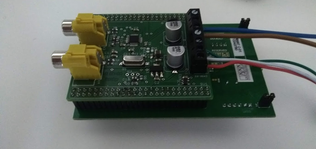
FB1 nd FB3 are open (3rd image) so no 1.8vA and AGND for tvp5150. just
bridge them with solder or use ferrite beads
Hoang Anh LeZoe schrieb:
> FB1 nd FB3 are open (3rd image) so no 1.8vA and AGND for tvp5150. just
> bridge them with solder or use ferrite beads

Thank you a lot. The ambilight works perfectly.
Good day.
Pitschu, your project is great!
I've read the forum but still don't understand is it open source project
or not =)
You has uploaded scheme, .hex code.
But there is a site with commercial boards:
http://www.keiang.de/Content-pid-61.html

I have F4-disco board, some stm32f407vgt6 mcu and I can produce pcb by
scheme from your post.
Need I extra source files or .hex only?
By the link below there is a last firmware that is assume presence of
bootloader http://www.keiang.de/Downloads-op-view-lid-83.html

Answer please =)
Best regards, Yuriy
Hi Yuriy,
you may use the sources I publshed for your personal projects only. If
you want to use it for comercial things, please tell me and we'll find a
solution.

Keiang offers a comercial product based on the same hardware components.
As he didn't publish any details, I do not know if his binary file works
on your hardware - probably not.

pitschu
Angehängte Dateien:
-

pitschuLight.GIF
160 KB
Hi, pitschu! =)
My TV use only)
I was searching for the easiest solution and everywhere was foundes
Raspbery Pi.
Your project most acceptable for me)
You use connectivity like on the image and
"Ambilight-STM32F4-GNUARM.hex" firmware, right?.
Does your project need some configurations?
How many WS2812 leds I can use?

Best regards, Yuriy
The images in your post are quite old ones (the first version). I posted
a newer version of the schematic and of the firmware over the time.
Please use the latest hard- and software.

The firmware (.HEX or .ELF) is complete and does not need any other
config files. The configuration is done via an USART interface (using
dedicated pins or the STM USB interface). You can switch them by
recompiling the sources. Another way to set several parameters is by
using a IR controller. Read my .PDF file I posted within the thread
(sorry, only in German :-( )
Hi,
after several tries to compile the project I hope to get some hints was
to try next. I hope this will help other too.

What I have done so far:

* sudo apt install arm-none-eabi-gcc openocd
* get "Eclipse IDE for C/C++ Developers"
(https://www.eclipse.org/downloads/packages/)
* get Plugin "GNU MCU Eclipse" (formerly GNU ARM Eclipse) from "Market
Place"
* Open Perspective "Packs" (in "Window/Perspective/Open
Perspective/Other")
* update the package definitions (might take several hours)
* installed packages "ARM/CMSIS", "ARM/CMSIS Driver",
"Keil/STM32F4xx_DFP"
* import the "source zip" as a project in eclipse
* clicked "Clean Project" and "Build Project"

Output:
1 | 08:38:16 **** Clean-only build of configuration Debug for project Ambilight-STM32F4-GNUARM-V1.2 **** |
2 | make clean |
3 | rm -rf Ambilight-STM32F4-GNUARM-V1.2.siz Ambilight-STM32F4-GNUARM-V1.2.hex Ambilight-STM32F4-GNUARM-V1.2.lst Ambilight-STM32F4-GNUARM-V1.2.elf |
4 | |
5 | |
6 | 08:38:16 Build Finished. 0 errors, 0 warnings. (took 280ms) |
7 | |
8 | |
9 | **** Build of configuration Debug for project Ambilight-STM32F4-GNUARM-V1.2 **** |
10 | |
11 | Nothing to build for project Ambilight-STM32F4-GNUARM-V1.2 |
What is wrong or missing here?

muebau
Hallo,
nun habe ich es nach langem Versuchen erfolgreich compiliert bekommen.

Mir sind einige Kleinigkeiten aufgefallen:

Das ist Semikolon ist da zuviel, nicht?
1 | --- system_stm32f4xx.c |
2 | +++ system_stm32f4xx.c |
3 | @@ -401,7 +401,7 @@ static void SetSysClock(void) |
4 | RCC->CFGR |= RCC_CFGR_SW_PLL; |
5 | |
6 | /* Wait till the main PLL is used as system clock source */
|
7 | - while ((RCC->CFGR & (uint32_t)RCC_CFGR_SWS ) != RCC_CFGR_SWS_PLL); |
8 | + while ((RCC->CFGR & (uint32_t)RCC_CFGR_SWS ) != RCC_CFGR_SWS_PLL) |
9 | {
|
10 | }
|
11 | }
|
Warum wird hier memset mit "0" aufgerufen?
1 | ambiLight.c: In function 'ambiLightInit': |
2 | ambiLight.c:79:2: warning: 'memset' used with constant zero length parameter; this could be due to transposed parameters [-Wmemset-transposed-args] |
3 | memset ((char*)&dynColumns[0], sizeof(dynColumns), 0); |
4 | ^~~~~~
|
5 | src/ambiLight.c:80:2: warning: 'memset' used with constant zero length parameter; this could be due to transposed parameters [-Wmemset-transposed-args] |
6 | memset ((char*)&dynRows[0], sizeof(dynRows), 0); |
7 | ^~~~~~
|
Hier warnt der Compiler wegen "aliasing" (mehrere Pointer verschienen
Typs auf einen Speicherbereich):
1 | --- usb_core.c |
2 | +++ usb_core.c |
3 | @@ -1104,6 +1104,7 @@ void USB_OTG_ActiveRemoteWakeup(USB_OTG_CORE_HANDLE *pdev) |
4 | if(pdev->cfg.low_power) |
5 | {
|
6 | /* un-gate USB Core clock */
|
7 | + #pragma GCC diagnostic ignored "-Wstrict-aliasing" |
8 | power.d32 = USB_OTG_READ_REG32(&pdev->regs.PCGCCTL); |
9 | power.b.gatehclk = 0; |
10 | power.b.stoppclk = 0; |
11 | @@ -1134,6 +1135,7 @@ void USB_OTG_UngateClock(USB_OTG_CORE_HANDLE *pdev) |
12 | if(dsts.b.suspsts == 1) |
13 | {
|
14 | /* un-gate USB Core clock */
|
15 | + #pragma GCC diagnostic ignored "-Wstrict-aliasing" |
16 | power.d32 = USB_OTG_READ_REG32(&pdev->regs.PCGCCTL); |
17 | power.b.gatehclk = 0; |
18 | power.b.stoppclk = 0; |
19 | diff --git a/src/usb_dcd_int.c b/src/usb_dcd_int.c |
20 | index 0596a91..27796e5 100644 |
21 | --- usb_dcd_int.c |
22 | +++ usb_dcd_int.c |
23 | @@ -164,6 +164,7 @@ static uint32_t DCD_HandleResume_ISR(USB_OTG_CORE_HANDLE *pdev) |
24 | if(pdev->cfg.low_power) |
25 | {
|
26 | /* un-gate USB Core clock */
|
27 | + #pragma GCC diagnostic ignored "-Wstrict-aliasing" |
28 | power.d32 = USB_OTG_READ_REG32(&pdev->regs.PCGCCTL); |
29 | power.b.gatehclk = 0; |
30 | power.b.stoppclk = 0; |
Besteht hier nicht die Gefahr das die Variable wegoptimiert wird und
damit das Register nicht gelesen wird?
1 | AvrXBufferedSerial.c:109:18: warning: unused variable 's' [-Wunused-variable] |
2 | volatile short s = USART3->DR; |
1 | if (USART3->SR & 0x0F) // if any error flag is 1 then read DR to clear them |
2 | {
|
3 | volatile short s = USART3->DR; |
4 | }
|
Good day!
Pitschu, I just want to thank you for this design :)
Everything works, but there are minor glitches.
Please tell me, because of what can there be a long response and a
periodic reset of the display?
Sometimes between the change of image and the change of backlight, up to
two seconds pass.
It is rare to turn off the backlight (feeling like a signal malfunction)
and turn it on after a few seconds.
At the same time, the area for display on the screen is not black, but
the STM32F407 works (I look at 4 LEDs).
At the moment, it is not possible to connect through the terminal while
the entire structure is working, therefore
I don’t know the state of the controller during the failure.
I am attaching an archive with a video and a couple of pictures (I
apologize for shaking hands))).


I connect it like this: PlayStation4-> HDMI Splitter-> HDMI to RCA
converter-> PCB + DiscoF4.
I tried to switch PAL / NTSC on the converter and did not notice the
difference.
Directly to connect to the TV via SCART-> RCA is not yet possible, I
will soon buy an adapter and try.
I use only 3 zones, without lower backlight. 16 LEDs high, 28 wide.
Power supply 220  12V and step-down stabilizer 12  5V 5A.
I also tried to power it from the laboratory power supply KA3005D,
failures still remain.

I configured the board through the terminal, the settings are as
follows:
H = 270, T = 30, W = 720, L = 88,
P = 28, R = 16, A = 1, M = 0,
F = 0, S = 128, B = 85, C = 90
I = 90, E = 5, Y = 40, X = 64.

Tell me what I can check.
Thank you in advance)
Best regards, Yuri
Hi Yuri,

I think the delay time of your device chain (Playstation -> splitter -
converter -> Ambilight) could be long, depending on the type of the
devices. One thing you could do in the Ambilight is to increase the
I-parameter to 128 (= instant display without integration).
Try to lower the G-parameter (# of frames for black-border-detection).
The default is 100 frames. Try smaller values.

pitschu
Good day.
Pitschu, thanks a lot for your project!!!
Everything works perfectly! =)
Finaly I use the following parameters:
I = 90, G = 80.
It was useful for me to reduce the length of the wires to the LED
backlight.
Also added a 100pF capacitor from PE9 to GND.

Thanks again!
Regards, Yuri
Hi Dear,
Firstly thanks for good project.
I want to use project could anybody share last version schematic and
source code for project.

Best Regard
Otto
Bitte melde dich an um einen Beitrag zu schreiben. Anmeldung ist kostenlos und dauert nur eine Minute.
Bestehender Account
Schon ein Account bei Google/GoogleMail? Keine Anmeldung erforderlich!
Mit Google-Account einloggen
Mit Google-Account einloggen
Noch kein Account? Hier anmelden.