Luca schrieb:
> I'd like to get the simulation working correctly so I can swap the
> optocouplers with different ones I have available and see if the
> waveform is still acceptable.
I'm not sure you'll find that used optokopplers in LTspice.

It's better to compare the datasheets of that selected optokopplers I'll
think.
Most important is the rise- and fall-time to get the best serial
signalisation.

Regards Norbert
Oh, I found a model online for the H11L1, the optocoupler I have
available has no schmitt trigger and even if it is slower it gave an
apparently good enough result in the receiver, but I'd like to simulate
the transmitter.
Angehängte Dateien:
-

bus_trasnmitter_4n25.png
22 KB
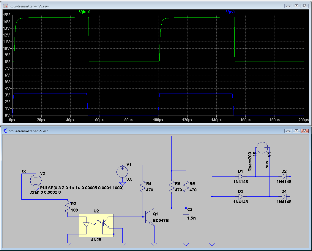
I came up with this circuit (I have some 4N25 around), do you think it
could work?
Angehängte Dateien:
Mmh, I put V1 on the bus side so I was losing the isolation provided by
the opto.
This is a revised version with the transmitter and receiver.
What do you think?
Luca schrieb:
> This is a revised version with the transmitter and receiver.
> What do you think?
Your simulated 4N25 seems to be fast enough to do the job.
But there are some problems with that design:
1. Q1 is closed (default current-flow) if V2 is low or disconnected.
-->> No 'failsave' available and blocking the heater-bus on failures.
2. D6 not required, but use the resistor-value with higher value.
3. UART-signals from MCU have high-levels in idle-mode, so your design
is wrong.
Please look at my design, strip it down and simulate this with the 4n25.

Regards Norbert
Hello,

thank you for your feedback, really appreciated.

Regarding 1., I didn't think of that, but since my bus is currently
unused and I will only connect this interface, in turn permanently
connected to an esp32 (so that V2, aka tx, will be idle high,
phototransistor of U2 closed, Q1 open, bus high), I'm not sure it is a
problem.

Regarding 2., good, I'll remove the zener and adjust the resistor.

Regarding 3., maybe the ltspice model I found of the H11L1 is wrong, but
when I simulated your transmitter it gave me the same result as my
circuit: tx high, (idle) green trace) -> bus high (blue trace), tx low
(transmitting) -> bus low.
Same for the receive side: bus high -> rx high, bus low -> rx low.
Should they be inverted?
Angehängte Dateien:
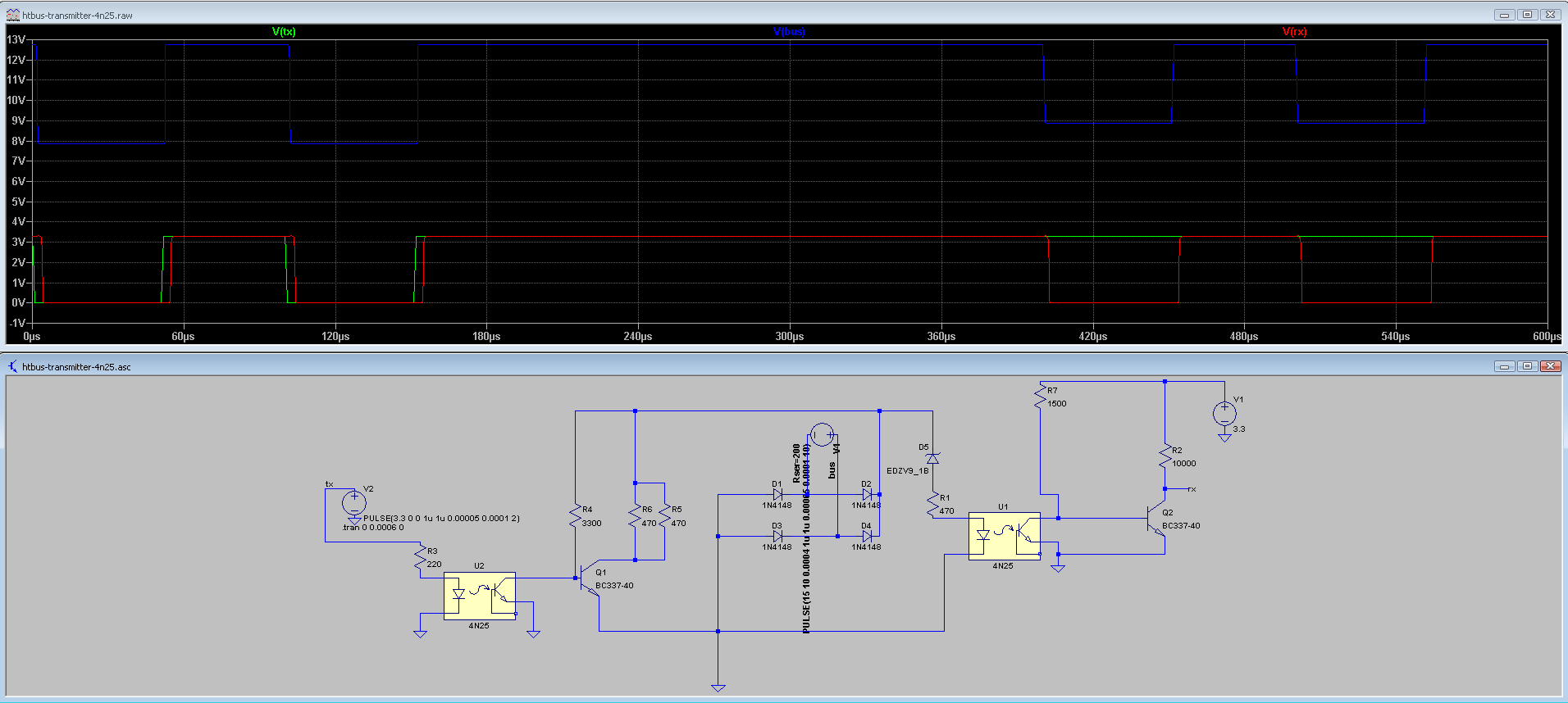
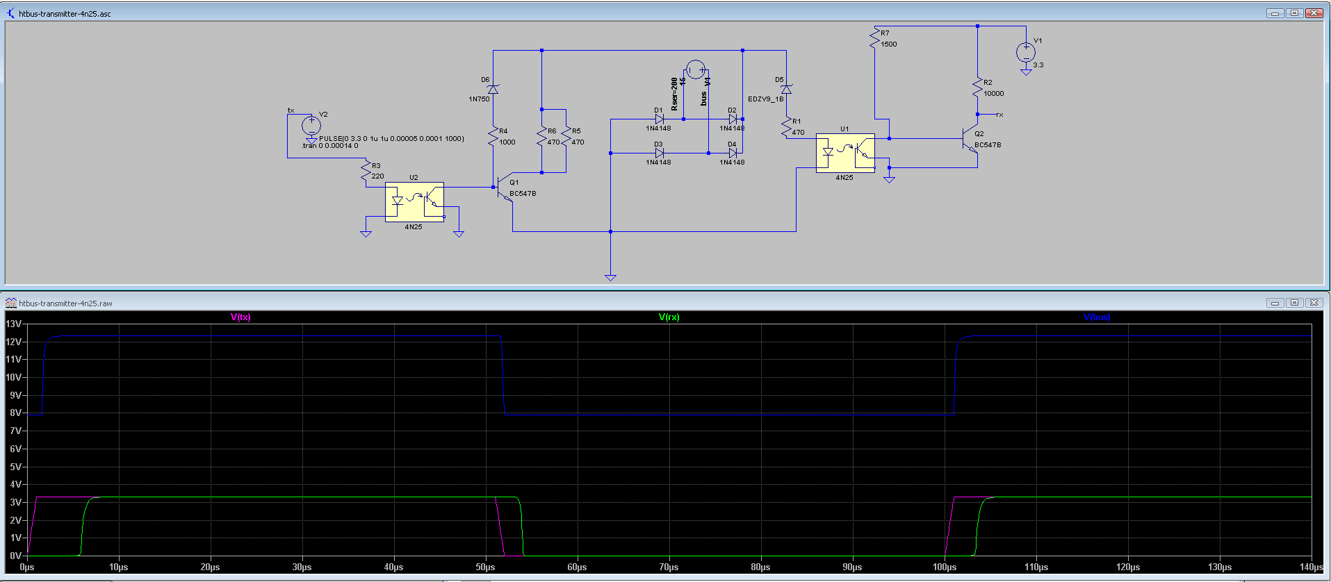
Latest iteration with the zener removed and changes in the simulation
(V2 simulates the transmission for a short while and after that V4
simulates the reception).

Edit: in the real circuit the GND in the middle won't be connected, but
AFAIK in ltspice it's needed otherwise it cannot simulate the circuit.
Angehängte Dateien:
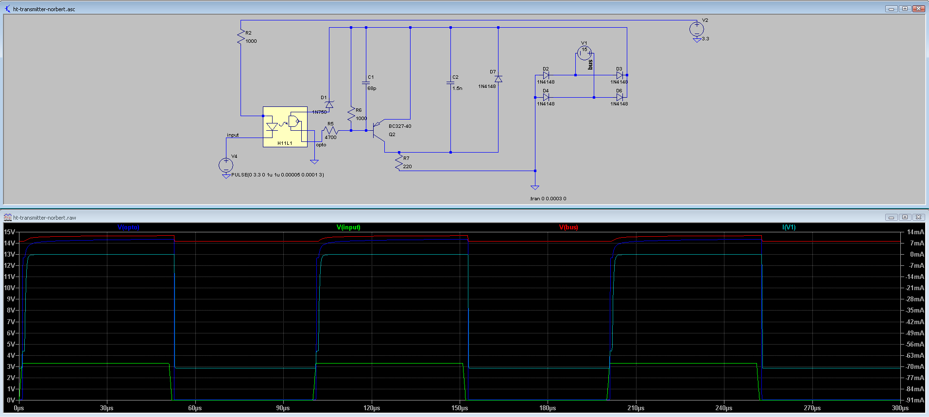
This is my attempt to simulate your circuit.
As I said in my first message, the voltage swing is very low, but the
current in the bus seems ok (70mA, not really sure it's actually ok).
But I see that it follows the input (input high -> optocoupler high ->
bus high, input low -> optocopler low -> bus low).
Hallo,

verkaufe einen original ht_pitiny. Bei Interesse per Mail melden.
Luca schrieb:
> This is my attempt to simulate your circuit.
> As I said in my first message, the voltage swing is very low, but the
> current in the bus seems ok
Thanks for your simulations-attempts.
Keep in mind that this heater-bus has NOT a full-duplex communication.
You have to simulate that RX-direction and the TX-direction separately
and not in one turn.

Regards Norbert
Norbert S. schrieb:
> Luca schrieb:
>> This is my attempt to simulate your circuit.
>> As I said in my first message, the voltage swing is very low, but the
>> current in the bus seems ok
> Thanks for your simulations-attempts.
> Keep in mind that this heater-bus has NOT a full-duplex communication.
> You have to simulate that RX-direction and the TX-direction separately
> and not in one turn.

Yes, that's what I did in htbus-transmitter-4n25.asc (*) (I first
simulate a couple of pulses in the tx side, then, after a delay, a
couple of pulses on the bus (to test the rx side).
In case of ht-transmitter-norbert.asc I only simulated the transmitter.

(*) It turns out that what I have available are 4n27 but the simulation
doesn't change.
Hi,

mein FW200 ignoriert irgendwie die (automatische?)
Sommer-/Winterzeitumstellung und verliert auf Dauer recht viel Zeit auch
wenn der Heizungsbauer mal dran. Leider ist sind hat es mit 2 Stunden
Verschiebung dann doch Auswirkung auf die Schaltprogramme...ist es
theoretisch möglich die Zeit auszulesen (Monitoring) und von außen zu
setzen (mit der öffentlichen Zeit über NTP) oder bietet der Bus das gar
nicht?

Viele Grüße,
Nils
Angehängte Dateien:
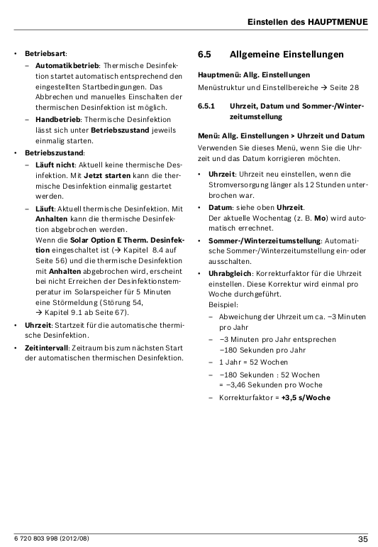
Nils R. schrieb:
> mein FW200 ignoriert irgendwie die (automatische?)
> Sommer-/Winterzeitumstellung und verliert auf Dauer recht viel Zeit auch
> wenn der Heizungsbauer mal dran. Leider ist sind hat es mit 2 Stunden
> Verschiebung dann doch Auswirkung auf die Schaltprogramme...
Hallo Niels,
die Zeit und Umschaltung lässt sich am FW200 einstellen, siehe Bild und
Bedienungsanleitung.
Auch der Korrekturfaktor ist einstellbar.

> ist es theoretisch möglich die Zeit auszulesen (Monitoring)
Die Zeit wird ohnehin jede Minute vom Regler gesendet, dies sieht man im
HT3_Analyser.
Allerdings wird diese nicht per MQTT-Meldung ausgegeben, habe bisher
keine Notwendigkeit gesehen.

> und Zeit von außen zu
> setzen (mit der öffentlichen Zeit über NTP) oder bietet der Bus das gar
> nicht?
Muss ich klären.

Gruß Norbert
Das wäre toll, danke.

Die automatische Umschaltung ist aktiv macht aber nichts. Dort hatte
mein Heizungsbauer schon bei Junkers nachgefragt, das Gerät war aber
bereits aus der Garantie.

Bei dem Zeitverlust kommt es m.E. eher daher, wenn mein Heizungsbauer
die Anlage stromlos macht. Aktuell habe ich 2 Stunden Zeitunterschied
und mein Mieter hat sich beschwert. Ich habe dort die Herausforderung
mit Hamburg das Mietobjekt und Rosenheim wohnhaft. Als ich selber noch
oben gewohnt habe war das einfach, jetzt ist es ein wenig nervig. Wenn
wäre eine sehr große Zeitkorrektur notwendig, ist aber schwierig zu
analysieren.
Angehängte Dateien:
-

Nils_systemtime_msg_6_0.png
340 KB
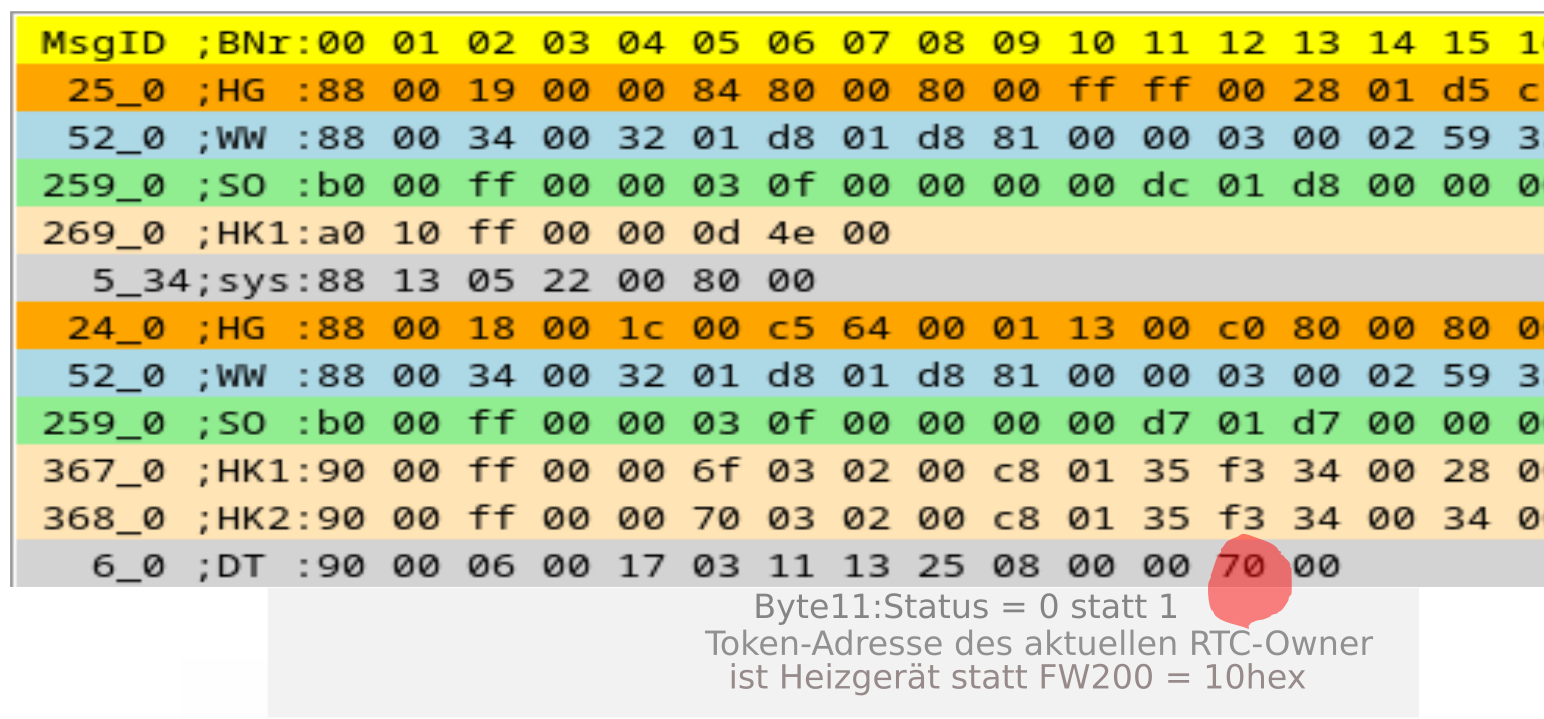
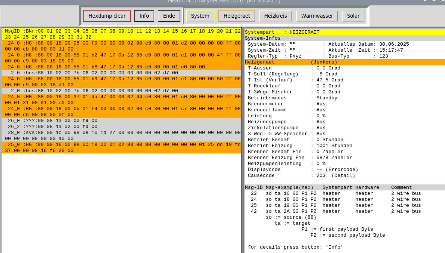
Norbert S. schrieb:
>> und Zeit von außen zu
>> setzen (mit der öffentlichen Zeit über NTP) oder bietet der Bus das gar
>> nicht?
> Muss ich klären.
Hallo Nils,
habe einiges probiert um die Zeit des Reglers über Telegramme von Aussen
zu verändern. Dies ist mir bisher nicht gelungen, habe zwar einen CW400
in meinem Heizungssystem aber offensichtlich gibt es dieses Problem auch
bei Fxyz Reglern von Junkers.
siehe dazu auch URL's:
https://github.com/emsesp/EMS-ESP32/issues/536
https://github.com/emsesp/EMS-ESP32/issues/666
https://github.com/emsesp/EMS-ESP32/issues/386

Habe mal Deine alten Log-Files mit dem Analyser auf die Uhrzeit
kontrolliert (siehe Bild).
Bei dem markiertem Telegram Msg:6_0 (Systemzeit) ist:
 der Status(Byte11) = 0 und
 der RTC-Owner(Byte12) = 70hex.
Dies bedeutet: Uhrzeit nicht gültig und die Zeit kommt vom Heizgerät
statt vom Regler.
Allerdings ist mir nicht bekannt wie man dieses ändern könnte, habe
keine Infos darüber in den Installations-Anweisungen gefunden.
Systemuhrzeit kann man eigentlich nur am Regler Fxyz/Cxyz
einstellen/konfigurieren.
Bei meinem System steht bei den Bytes:
 der Status(Byte11) = 1 und
 der RTC-Owner(Byte12) = 10hex <<-- Geräteadresse des Reglers.

Nils R. schrieb:
> Bei dem Zeitverlust kommt es m.E. eher daher, wenn mein Heizungsbauer
> die Anlage stromlos macht.
Die Regler haben keine Batterie aber eine Super-CAP. Die speichert die
Daten und betreibt die Uhr für eine begrenzte Zeit.
Daher nehme ich an das diese Super-CAP defekt ist. Ein Tausch könnte das
Problem vielleicht ja beseitigen.

Frage: Du hast ja noch ein MBLAN2 im Heizungssystem. Läßt sich damit die
Systemzeit einstellen?

Gruß Norbert
Ich habe bei mir eine Konfiguration aus CW400, Solar mit MS200,
Fußbodenheizkreis mit MM100 und Frischwasserstation mit MS100. Bislang
ist die Anlage komplett außentemperaturgesteuert - hat aber
Raumtemperaturregler an den Stellantrieben der Fußbodenheizung. Das
führt zu so "tollen" Situationen das der Raumtemperaturregler sagt
"bitte Wärme", die Heizung aber den Heizkreis schon abgeschaltet hat
"weils draußen zu warm ist".

Da die Stellantriebe auch Strom verbrauchen wenn der Heizkreis aus ist
habe ich einen HT3-Reader entwickelt der ein bistabiles Relais
umschaltet wenn der Heizkreis an- oder abschaltet. Damit steuere ich nun
die Stromversorgung der Stellantriebe.

Den Stromverbrauch der Stellantriebe messe ich zusätzlich mit mehreren
umgebauten PZEM-004T 10A Modulen. Meine Idee ist nun ein CR10 zu
"emulieren", d.h. anhand des gemessenen Stroms die Solltemperatur (oder
Isttemperatur?) vorzugeben und das CW400 damit zu steuern.

Dafür hab ich mir ein gebrauchtes CR10 besorgt um dessen Telegramme
mitlesen zu können. Laut HT_EMB_Bus_messages.pdf soll ein CR10 als
Fernbedienung eine Busaddresse von 0x18 haben. Das ist bei mir aber nur
so wenn das CR10 als Regler statt als Fernbedienung läuft. Und dann
bekomme ich den Fehler "zwei Regler konfiguriert". Wenn ich dann den
CR10 auf Fernbedienung umschalte wird er zu 0x38 "Fernbedienung
Heizkreis 9"?

Die Telegramme gibt es scheinbar noch nicht und so ganz schlau werde ich
daraus leider nicht:
1 | 30.04.2025;11:20:39;DEBUG;1067_0 ;???;S38;T10;1067_0 ;???:b8 10 ff 00 03 2b 00 dc 08 9c 01 de 00 |
2 | 30.04.2025;11:21:39;DEBUG;1067_0 ;???;S38;T10;1067_0 ;???:b8 10 ff 00 03 2b 00 dc 08 9c 01 de 00 |
3 | 30.04.2025;11:22:39;DEBUG;1067_0 ;???;S38;T10;1067_0 ;???:b8 10 ff 00 03 2b 00 dc 08 9c 01 de 00 |
4 | 30.04.2025;11:23:16;DEBUG; 191_0 ;sys;S38;T00; 191_0 ;sys:b8 00 bf 00 38 a5 00 00 00 00 00 00 00 00 00 00 00 00 00 00 00 00 00 00 00 00 00 00 af 00 |
5 | 30.04.2025;11:23:39;DEBUG;1067_0 ;???;S38;T10;1067_0 ;???:b8 10 ff 00 03 2b 00 dc 08 9c 01 de 00 |
6 | 30.04.2025;11:24:38;DEBUG;1067_0 ;???;S38;T10;1067_0 ;???:b8 10 ff 00 03 2b 00 dc 08 9c 01 de 00 |
7 | 30.04.2025;11:25:39;DEBUG;1067_0 ;???;S38;T10;1067_0 ;???:b8 10 ff 00 03 2b 00 dc 08 9c 01 de 00 |
8 | 30.04.2025;11:26:38;DEBUG;1067_0 ;???;S38;T10;1067_0 ;???:b8 10 ff 00 03 2b 00 dc 08 9c 01 de 00 |
9 | 30.04.2025;11:27:39;DEBUG;1067_0 ;???;S38;T10;1067_0 ;???:b8 10 ff 00 03 2b 00 dc 08 9c 01 de 00 |
10 | 30.04.2025;11:28:38;DEBUG;1067_0 ;???;S38;T10;1067_0 ;???:b8 10 ff 00 03 2b 00 dc 08 9c 01 de 00 |
11 | 30.04.2025;11:29:38;DEBUG;1067_0 ;???;S38;T10;1067_0 ;???:b8 10 ff 00 03 2b 00 dc 08 9c 01 de 00 |
12 | 30.04.2025;11:30:39;DEBUG;1067_0 ;???;S38;T10;1067_0 ;???:b8 10 ff 00 03 2b 00 dc 08 9c 01 de 00 |
13 | 30.04.2025;11:31:38;DEBUG;1067_0 ;???;S38;T10;1067_0 ;???:b8 10 ff 00 03 2b 00 dc 08 9c 01 de 00 |
14 | 30.04.2025;11:32:38;DEBUG;1067_0 ;???;S38;T10;1067_0 ;???:b8 10 ff 00 03 2b 00 dc 08 9c 01 de 00 |
15 | 30.04.2025;11:33:15;DEBUG; 191_0 ;sys;S38;T00; 191_0 ;sys:b8 00 bf 00 38 a5 00 00 00 00 00 00 00 00 00 00 00 00 00 00 00 00 00 00 00 00 00 00 af 00 |
16 | 30.04.2025;11:33:37;DEBUG;1067_0 ;???;S38;T10;1067_0 ;???:b8 10 ff 00 03 2b 00 dc 08 9c 01 de 00 |
17 | 30.04.2025;11:34:38;DEBUG;1067_0 ;???;S38;T10;1067_0 ;???:b8 10 ff 00 03 2b 00 dd 08 9e 01 d2 00 |
18 | 30.04.2025;11:35:37;DEBUG;1067_0 ;???;S38;T10;1067_0 ;???:b8 10 ff 00 03 2b 00 dd 08 a2 01 aa 00 |
19 | 30.04.2025;11:36:37;DEBUG;1067_0 ;???;S38;T10;1067_0 ;???:b8 10 ff 00 03 2b 00 dd 08 a4 01 a6 00 |
Der erste Wert nach der Telegramm-ID ist 0x00dd und entspricht der
Raumtemperatur Ist die im HT3_Analyzer angezeigt wird. Der Sollwert war
ab 11:20 Uhr auf 27.5 Grad eingestellt ... kann ich irgendwie nicht
zuordnen.

Zwischendurch sendet das CR10 noch eine "hab keine Fehler" Meldung. Aber
das war es dann leider auch schon...

@Norbert S. Hattest Du nicht auch eine CW400 + CR10? Wundert mich das
die Telegramme unbekannt sind...
Jochen D. schrieb:
> Die Anlage ist komplett außentemperaturgesteuert - hat aber
> Raumtemperaturregler an den Stellantrieben der Fußbodenheizung. Das
> führt zu so "tollen" Situationen das der Raumtemperaturregler sagt
> "bitte Wärme", die Heizung aber den Heizkreis schon abgeschaltet hat
> "weils draußen zu warm ist".
Die Raumtemperaturregler wissen ja nichts von der aktuellen
Aussentemperatur und sind ja wohl nicht mit dem Heizungsbus verbunden.
Daher dieses Verhalten.
Wichtig dabei ist bei der Inbetriebnahme des CW400 die korrekte
Gebäudeart einzustellen (Leicht/Mittel/Schwer).
Dadurch werden Aussentemperatur-Änderungen in der CW400 Regelung
verzögert behandelt.

> Da die Stellantriebe auch Strom verbrauchen wenn der Heizkreis aus ist
> habe ich einen HT3-Reader entwickelt der ein bistabiles Relais
> umschaltet wenn der Heizkreis an- oder abschaltet.
> Den Stromverbrauch der Stellantriebe messe ich zusätzlich mit mehreren
> umgebauten PZEM-004T 10A Modulen.
Hast Du diesen Strombedarf der Stellantriebe schon einmal gemessen?
Soweit ich weiss brauchen die Stellantriebe nur Strom wenn diese die
Ventile verstellen, ansonsten brauchen diese keinen Strom ausser der
Steuerelektronik.
Diese PZEM-004T 10A Module brauchen ja auch Strom.

Wenn Du wirklich Strom sparen willst mache bitte fogendes:
1. Alle Stellantriebe auf maximal offen einstellen oder ganz entfernen.
2. Elektronik und Versorgung der Stellantriebe ausschalten.
3. Hydraulischen Abgleich der Fussbodenheizung durchführen.
4. Durchflussmengen der einzelnen Heizkreise an den Bedarf anpassen.
5. Regler CW400 optimal einstellen, eventuell den Regler im Führungsraum
(Wohnzimmer etc.) plazieren und ihn dort die Raum-Temperatur messen
lassen.
Der CR10 ist dann nicht mehr nötig.
Auf diese Art betreibe ich meine Anlage seit mehreren Jahren mit
Fussbodenheizungen in zwei Etagen und mit 9- und 7-fach
Heizkreis-Verteilern.
Bin kein Heizungsfachmann, aber dies habe ich für mich als am besten
geeignet herausgefunden.

> @Norbert S. Hattest Du nicht auch eine CW400 + CR10? Wundert mich das
> die Telegramme unbekannt sind...
Ja, den CR10 hatte ich im System. Brauche ich aber nicht mehr, siehe
oben.
Die Telegramme sind bekannt, nur nicht im Dokument enthalten.

> Wenn ich dann den
> CR10 auf Fernbedienung umschalte wird er zu 0x38 "Fernbedienung
> Heizkreis 9"?
Ja, diese Modul-Adresse 0x38 hatte mein CR10 ebenfalls. Die Einstellung
ist korrekt.

> Der erste Wert nach der Telegramm-ID ist 0x00dd und entspricht der
> Raumtemperatur
Ja, stimmt.
Die folgenden zwei Bytes: (z.B. 08 9e) sind 'Raumtemperatur
hochauflösend'
Das letzte Daten-Byte: 01 ist 'Gültigkeitsflag der Raumtemperatur'.

Gruß Norbert
Norbert S. schrieb:
> Jochen D. schrieb:
>> Da die Stellantriebe auch Strom verbrauchen wenn der Heizkreis aus ist
>> habe ich einen HT3-Reader entwickelt der ein bistabiles Relais
>> umschaltet wenn der Heizkreis an- oder abschaltet.
>> Den Stromverbrauch der Stellantriebe messe ich zusätzlich mit mehreren
>> umgebauten PZEM-004T 10A Modulen.
> Hast Du diesen Strombedarf der Stellantriebe schon einmal gemessen?
> Soweit ich weiss brauchen die Stellantriebe nur Strom wenn diese die
> Ventile verstellen, [...]

So ein thermischer Stellantrieb braucht am Anfang 8W und fällt dann
innerhalb von 45 Sekunden auf 3W ab. Dadurch das der Stift am
Stellantrieb thermisch geschlossen wird haben die Teile einen gewissen
Vorlauf/Nachlauf.

> Diese PZEM-004T 10A Module brauchen ja auch Strom.

Naja, das hält sich IMHO gegenüber den Stellantrieben ja in Grenzen.
Desweiteren baue ich die um sodass die ausschließlich über 5V versorgt
werden...

> Wenn Du wirklich Strom sparen willst mache bitte fogendes:

Strom sparen steht nicht im Vordergrund. Strom unsinnig verbrauchen,
also Stellantriebe versorgen wenn die Heizungspumpe nicht läuft habe ich
ja schon durch mein Mithörmodul gelöst. Funktioniert auch einwandfrei!

Komfort erhöhen ist mein Ziel. Durch die Änderung von
außentemperaturgeführt auf raumtemperaturgeführt macht die Heizung nun
schon eher das was ich möchte und nicht das was die Heizung "denkt" was
für mich ausreichend wäre... Wenn ich die Schwellen zu tief setze heizt
sie "gefühlt" zu wenig, wenn ich die Schwellen zu hoch setze heizt sie
auch noch bei 20 Grad Außentemperatur ... Ist ja an den Diagrammen schön
abzulesen...

> [...]
> 5. Regler CW400 optimal einstellen, eventuell den Regler im Führungsraum
> (Wohnzimmer etc.) plazieren und ihn dort die Raum-Temperatur messen
> lassen.

Ja, so hatte ich das vormals im Reiheneckhaus. Wenn es im Wohnzimmer
schön warm war schaltete die Heizung ab und das im Keller gelegene
gelegentlich beheizbare Zimmer konnte nie mehr warm werden oder wurde
arschkalt. Was dazu führte das der Regler im Führungsraum immer auf 30°C
gestellt wurde.

Nun im Haus ist die Wohnraumsituation komplexer und meine bessere Hälfte
hat in der Übergangszeit keine Lust auf kalte Räume weil es der Heizung
warm genug ist. Die gelegentlich beheizbaren Kellerräume gibt es auch
wieder. Genauso haben wir Gästezimmer die nur bei Bedarf (einmal die
Woche) beheizt werden (auf Temperatur X, wie es eben die Gäste wünschen
und nicht unsere Heizung) oder ein Wohnzimmer das auch mal um 2 Grad
angehoben werden soll..

> Die Telegramme sind bekannt, nur nicht im Dokument enthalten.

Schade schade ...

>> Der erste Wert nach der Telegramm-ID ist 0x00dd und entspricht der
>> Raumtemperatur
> Ja, stimmt.
> Die folgenden zwei Bytes: (z.B. 08 9e) sind 'Raumtemperatur
> hochauflösend'

Ah, Temperatur / 1000 .. Danke.

> Das letzte Daten-Byte: 01 ist 'Gültigkeitsflag der Raumtemperatur'.

Wie aber setzt der CR10 eine Solltemperatur?

Gruß

   Jochen
Norbert S. schrieb:
> https://github.com/emsesp/EMS-ESP32/issues/536
> https://github.com/emsesp/EMS-ESP32/issues/666
> https://github.com/emsesp/EMS-ESP32/issues/386
>
> Habe mal Deine alten Log-Files mit dem Analyser auf die Uhrzeit
> kontrolliert (siehe Bild).
> Bei dem markiertem Telegram Msg:6_0 (Systemzeit) ist:
>  der Status(Byte11) = 0 und
>  der RTC-Owner(Byte12) = 70hex.
> Dies bedeutet: Uhrzeit nicht gültig und die Zeit kommt vom Heizgerät
> statt vom Regler.

Das stimmt auch, ich hab eine witterungsgeführte Anlage.

> Allerdings ist mir nicht bekannt wie man dieses ändern könnte, habe
> keine Infos darüber in den Installations-Anweisungen gefunden.
> Systemuhrzeit kann man eigentlich nur am Regler Fxyz/Cxyz
> einstellen/konfigurieren.
> Bei meinem System steht bei den Bytes:
>  der Status(Byte11) = 1 und
>  der RTC-Owner(Byte12) = 10hex <<-- Geräteadresse des Reglers.
>
> Frage: Du hast ja noch ein MBLAN2 im Heizungssystem. Läßt sich damit die
> Systemzeit einstellen?

Ich hab ein MBLAN2, aber das kann eigentlich nix. Ich bräuchte ein KNX10
und einen CW Regler, dort soll man laut der Anleitung den Wert ändern
können.
https://manualzz.com/doc/4406681/junkers-knx-10-knx-gateway-installationsanleitung?p=6

Somit scheint es jedenfalls bei einigen Regeln zu funktionieren. Wenn
die Uhrzeit angezeigt wird wäre es auch erstmal toll, dann kann ich
Abweichungen erkennen ohne auf die Änderung der Betriebsart zu schauen.
Angehängte Dateien:
-

Sysdatetime_db_sqlite.png
110 KB
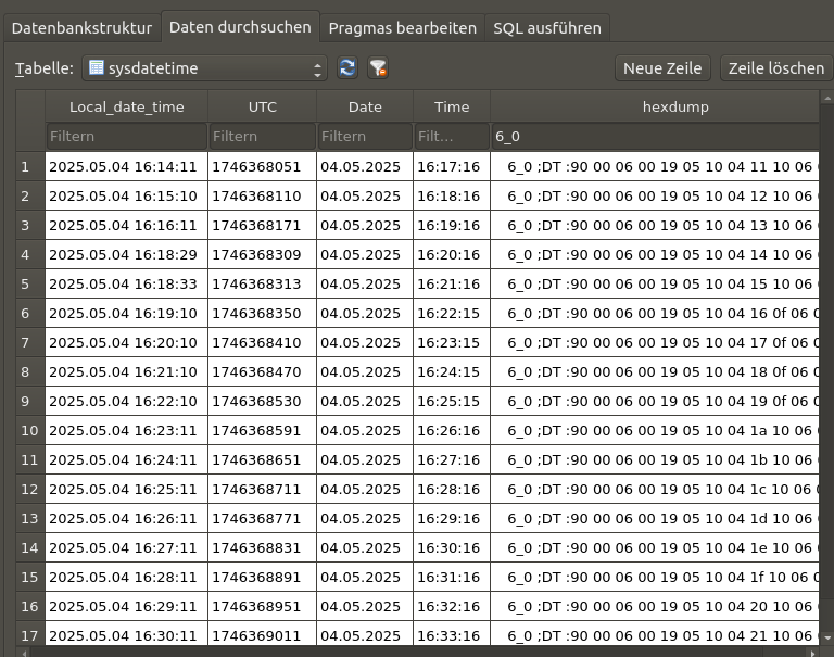
Nils R. schrieb:
> Ich hab ein MBLAN2, aber das kann eigentlich nix.
Dies liegt wohl weniger am MBLAN2 sondern am Regler-Typ, ob dieser ein
Fxyz- oder ein Cxyz-Typ ist.
Die Software im MBLAN2 wird automatisch dem entsprechenden Regler-Typ
angepasst, sobald das MBLAN2 mit dem Heizungsbus und dem Junkers-Server
verbunden ist.

> Ich bräuchte ein KNX10 und einen CW Regler...
Wahrscheinlich nur einen CW Regler (EMS2-Telegramme), ohne KNX10.
Allerdings musst Du dann alle Fxyz-Busmodule gegen die Cxzy-Module
(EMS2) austauschen.
Das wird dann teuer, da ist es wohl besser einen gebrauchten Fxyz Regler
als Ersatz zu erwerben.
Die Zeiteinstellung ist offensichtlich nur bei den Cxyz-Reglern möglich.

> Wenn die Uhrzeit angezeigt wird wäre es auch erstmal toll, dann kann ich
> Abweichungen erkennen ohne auf die Änderung der Betriebsart zu schauen
Wenn die sqlite-Datenbank aktiviert ist, werden u.A. die Zeitstempel der
RPi-localen Zeit und der Heizungssystemzeit eingetragen.
Dies wäre eventuell eine kurzfristige Lösung für Dich (siehe Bild).

Einfacher geht es natürlich mit den Tools:
1. HT3_Analyser.py oder
2. HT3_Systemstatus.py
Damit werden die Zeiten direkt angezeigt.

Gruß Norbert
Hallo zusammen,

ich habe eine Junkers ZB 7-22 A21

https://www.manualslib.de/products/Junkers-Zb-7-22-A-21-1086552.html

und brauche nur ein Signal ob die Heizung wirklich in der Nachtabsenkung
ist oder nicht.

Als Beispiel:

0V : Nachtabsenkung "Mond"
5V : Tagbetrieb "Sonne"

Hat jemand eine Idee ob und wie ich an dieses Signal kommen kann ohne
unendlich viel Aufwand - stecke in dem Bussystem nicht im Detail drin.

Danke.

VG
Jochen D. schrieb:
>> Die folgenden zwei Bytes: (z.B. 08 9e) sind 'Raumtemperatur
>> hochauflösend'
>
> Ah, Temperatur / 1000 .. Danke.
Nein, Temperatur / 100. -->> (0894)hex = (2206)dez. -->>
Raumtemperatur ist dann: 2206/100:= 22,06 Grad.

> Nun im Haus ist die Wohnraumsituation komplexer und meine bessere Hälfte
> hat in der Übergangszeit keine Lust auf kalte Räume weil es der Heizung
> warm genug ist.
OK, das ist dann wirklich schwierig.
Sind denn in allen Räumen Fussbodenheizungen?
Da ja ein Mischermodul MM100 vorhanden ist wird wohl nicht alles
Fussbodenheizung sein, oder?
Ich frage deshalb, weil ja die Reaktionszeiten auf Wärmeanforderungen
zwischen Fussbodenheizungen und Radiatoren doch extrem unterschiedlich
sind.
Da ist es dann auch wichtig welcher Raum mit welchem Heizungssystem als
Führungsraum mit zugehörigem Sensor dient.

> Wie aber setzt der CR10 eine Solltemperatur?
Wenn Du die gewünschte Temperatur für den jeweiligen Betriebsmoduls
ändern willst ist dies jetzt schon ohne CR10 und nur mit dem CW400
möglich.
Voraussetzung ist ein aktiver Adapter ht_pitiny bzw. ht_piduino.
Gruß Norbert
Angehängte Dateien:
-

ht3_reader.png
20 KB
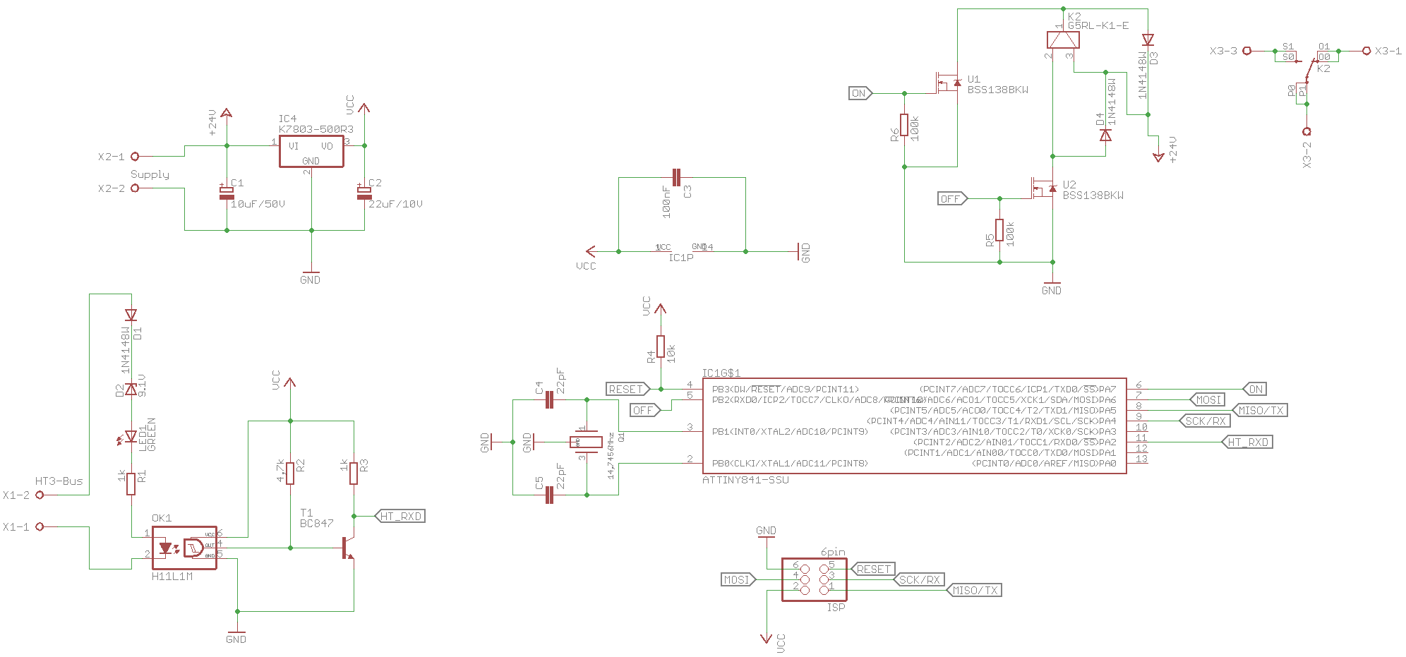
Martin S. schrieb:
> ich habe eine Junkers ZB 7-22 A21
> und brauche nur ein Signal ob die Heizung wirklich in der Nachtabsenkung
> ist oder nicht.
> Hat jemand eine Idee ob und wie ich an dieses Signal kommen kann ohne
> unendlich viel Aufwand - stecke in dem Bussystem nicht im Detail drin.

Kommt drauf an was "unendlich viel Aufwand" für Dich bedeutet. Ich hab'
mit Hilfe von Norbert einen HT3-Reader "entwickelt". Der ist komplett
autark. Den kann man an den HT3-Bus hängen und der hat ein bistabiles
Relais drauf. In Software kann man dann "einfach" auf Inhalte des
Protokolls reagieren. Ist aber für 24V konstruiert / ausgelegt - weil es
das bei mir überall gibt. Zudem sind die meisten Bauteile in SMD, weil
bei mir SMD State-of-the-art geworden ist...

Hab' mal das Projekt und den Schaltplan angehängt.. vielleicht kann das
ja jemand brauchen. Bei Bedarf / Interesse kann ich auch noch das
Programm dazuliefern, ist gerade nur in einer VM drin...

Gruß Jochen
Norbert S. schrieb:
> Jochen D. schrieb:
> Sind denn in allen Räumen Fussbodenheizungen?
> Da ja ein Mischermodul MM100 vorhanden ist wird wohl nicht alles
> Fussbodenheizung sein, oder?

Doch ist alles Fussbodenheizung. Keine Ahnung warum ich so eine
komplizierte Anlage habe, war wohl im Anlagenvorschlagsbüchlein meines
Handwerkers so drin...

> Ich frage deshalb, weil ja die Reaktionszeiten auf Wärmeanforderungen
> zwischen Fussbodenheizungen und Radiatoren doch extrem unterschiedlich
> sind.

Ja, aber selbst bei Fussbodenheizung schafft die Gastherme es in zwei
Stunden eine fühlbare Änderung der Temperatur zu erzeugen.

> Da ist es dann auch wichtig welcher Raum mit welchem Heizungssystem als
> Führungsraum mit zugehörigem Sensor dient.

Bislang war das ja ausschließlich außentemperaturgeführt.

> Wenn Du die gewünschte Temperatur für den jeweiligen Betriebsmoduls
> ändern willst ist dies jetzt schon ohne CR10 und nur mit dem CW400
> möglich.
> Voraussetzung ist ein aktiver Adapter ht_pitiny bzw. ht_piduino.

Ja gerade mal ausprobiert. Das funktioniert ;) Nur würde mich
interessieren welches Kommando da verschickt wird um temporär die
Solltemperatur vom Heizkreis 1 zu ändern. Und warum ich vom CR10 im
HT3-Analyzer dazu nix gesehen habe als ich am Rädchen vom CR10 drehte...

Gruß Jochen
Cool, ist die Info sogar schon da. Das werde ich mal nutzen, aktuell
verliert die Heizung in 1-2 Monaten den kompletten Druck daher ist der
Heizungsbauer häufiger da. (da ist die Auswertung des Systemdruck schon
super :-) )

Wenn das mittelfristig auf MQTT mit ausgegeben werden könnte wäre das
toll Dann würde ich das einfach in NodeRed mit einem Alarm versehen bei
zu großer Abweichung und auch die Kalibrierung mit den Daten machen
können.

Die Investition in einen neuen Regler würde ich überspringen, das ist ja
schon etwas mehr und erreicht nicht den Mehrwert dafür.
Angehängte Dateien:
-

Junkers_ZB_TA250.png
34 KB
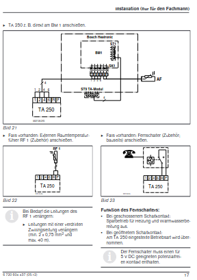
Jochen D. schrieb:
> Martin S. schrieb:
>> ich habe eine Junkers ZB 7-22 A21
>> und brauche nur ein Signal ob die Heizung wirklich in der Nachtabsenkung
>> ist oder nicht.
>> Hat jemand eine Idee ob und wie ich an dieses Signal kommen kann ohne
>> unendlich viel Aufwand - stecke in dem Bussystem nicht im Detail drin.
>
> Kommt drauf an was "unendlich viel Aufwand" für Dich bedeutet. Ich hab'
> mit Hilfe von Norbert einen HT3-Reader "entwickelt". Der ist komplett
> autark.
Leider hat der Junkers ZB 7-22 A21 einen HEATRONIC (4-Draht) Bus, der
nicht zum HEATRONIC3 Bus kompatibel ist. Daher kann der HT3-Reader nicht
dafür verwendet werden.

Martin S. schrieb:
> 0V : Nachtabsenkung "Mond"
> 5V : Tagbetrieb "Sonne"
Diese zeitliche Umschaltung macht der Regler zusammen mit der Schaltuhr.
Beim TA250 kann man einen externen Schalter anschliessen, der diese
Umschaltung erzwingt.
Anschluss beim TA250 siehe Bild.
Vielleicht verwendest Du einen ähnlichen Regler und eine Schaltuhr, die
dieses Signal ausgibt.
Weitere Details kenne ich allerdings nicht, da ich dies System nicht
habe.
Gruß Norbert
Angehängte Dateien:
-

Unbenannt.JPG
240 KB -

HT3_USB_MicroAdapter_Schaltplan.png
15 KB
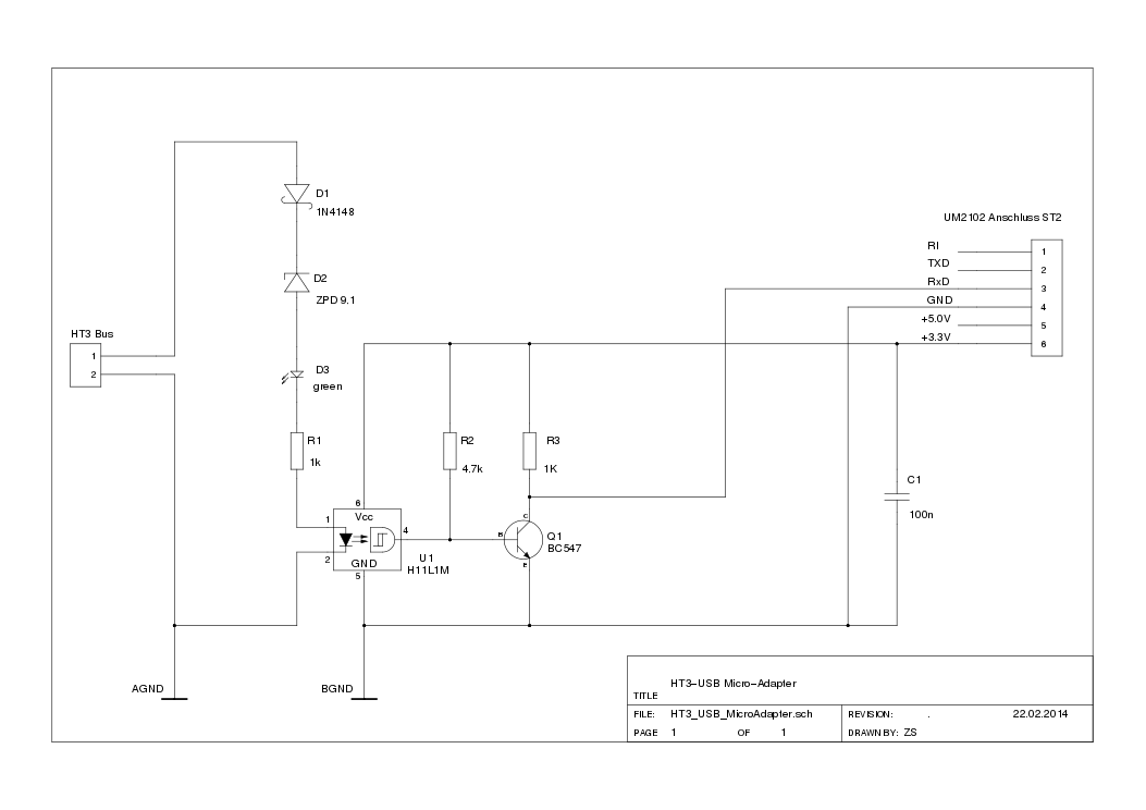
Hi zusammen,

habe hier seit Ewigkeiten einen HT_Microadapter über USB-TTL an meinem
Raspberry angeschlossen. Auf einmal empfange ich nur noch sehr selten
Telegramme und der Adapter überträgt auch Meldungen wie
"Warmwassersofort-Funktion" nicht mehr. Habe keinen Plan woher das
kommt.
Habe hier noch einen EMS-ESP am Bus und die Junkers Therme liefert dort
sauber Werte. Aber mit HT3-Analyser oder HT3-Systemstatus sieht das sehr
kaputt aus.

Wie kann ich rausfinden, was kaputt ist? Würde ja auf die Hardware vom
ht-microadapter tippen. Ist der angehängte Schaltplan noch aktuell und
richtig? Also die grüne LED leuchtet und auch der USB-TTL-Adapter
flackert schnell auf der RX-LED?

Danke.

Gruß kami
Stefan S. schrieb:
> Würde ja auf die Hardware vom ht-microadapter tippen.
Glaube ich weniger, da ist ja kaum etwas was kaputt gehen kann.

> Ist der angehängte Schaltplan noch aktuell und richtig?
Ja

> Habe keinen Plan woher das kommt.
Was hat sich in der nahen Vergangenheit am RaspberryPi geändert?
Ist neue Hardware oder Software installiert worden, z.B. FHEM oder
ähnliches.
Ist außer den üblichen Software-Updates sonst noch etwas installiert
worden?
Ist die Projekt-Software auf dem aktuellen Stand?

> Also die grüne LED leuchtet und auch der USB-TTL-Adapter
> flackert schnell auf der RX-LED?
Dann kommen auch Daten rein.

> Wie kann ich rausfinden, was kaputt ist?
Am besten mit einem Terminal-Programm auf der seriellen Schnittstelle
kontrollieren ob Daten kommen (z.B. miniterm).
Dazu den ht_proxy.py und ht_collgate.py stoppen damit der serielle Port
freigegeben wird und dann das Terminal-Programm mit 9600Baud 8N1 am
seriellen Port Daten empfangen lassen.
Gruß Norbert
Hi,

okay also Daten kommen rein. Kann ich per miniterm.py gut sehen. Da ist
viel Trubbel auf dem Bus.

Aber ich kriege bei collgate im Log immer folgenden Output:

02.07.2025 19:55:40 INFO: Starting 'Ccollgate.run()
02.07.2025 19:55:40 CRITICAL: cht_if_worker();Error;couldn't open
requested socket; cfg-file:/home/pi/HT3/sw/etc/config/ht_proxy_cfg.xml
02.07.2025 19:55:40 CRITICAL: ccollgate().run();Error;could not start
'ht-interface' with file:'./etc/config/HT3_db_cfg.xml'
02.07.2025 19:55:40 CRITICAL: ccollgate().run();Error; terminated

hab aber eigentlich nix an der Config geändert??

Danke.

Gruß kami
Stefan S. schrieb:
> Aber ich kriege bei collgate im Log immer folgenden Output:
> 02.07.2025 19:55:40 INFO: Starting 'Ccollgate.run()
> 02.07.2025 19:55:40 CRITICAL: cht_if_worker();Error;couldn't open
> requested socket; cfg-file:/home/pi/HT3/sw/etc/config/ht_proxy_cfg.xml
Dies kann z.B. an einem schon belegten Port oder IP-Adresse liegen.
ht_proxy.py verwendet z.Zeit die Port-Nummer: 48088.
PS:
Diese musste ich in der Vergangenheit auf diesen Wert anpassen weil
HomeAssistant die Port-Nr 8088 belegt.

Falls also bei Dir irgend eine andere Software-Instanz in Deinem lokalen
Netz die IP-Adresse und/oder Portnummer verwendet, kann es zu dieser
Fehlermeldung kommen.
Check ist unter linux möglich (als root) mit:
 lsof -i -P -n
Dies zeigt die Prozesse mit Verbindungen und Portnummern (sockets) auf.
Die Ausgabe bitte auf Doppelbelegung und Portnummer: 48088 checken.
Gruß Norbert
Norbert S. schrieb:
> Stefan S. schrieb:
>> Aber ich kriege bei collgate im Log immer folgenden Output:
>> 02.07.2025 19:55:40 INFO: Starting 'Ccollgate.run()
>> 02.07.2025 19:55:40 CRITICAL: cht_if_worker();Error;couldn't open
>> requested socket; cfg-file:/home/pi/HT3/sw/etc/config/ht_proxy_cfg.xml
> Dies kann z.B. an einem schon belegten Port oder IP-Adresse liegen.
> ht_proxy.py verwendet z.Zeit die Port-Nummer: 48088.
> PS:
> Diese musste ich in der Vergangenheit auf diesen Wert anpassen weil
> HomeAssistant die Port-Nr 8088 belegt.
>
> Falls also bei Dir irgend eine andere Software-Instanz in Deinem lokalen
> Netz die IP-Adresse und/oder Portnummer verwendet, kann es zu dieser
> Fehlermeldung kommen.
> Check ist unter linux möglich (als root) mit:
>  lsof -i -P -n
> Dies zeigt die Prozesse mit Verbindungen und Portnummern (sockets) auf.
> Die Ausgabe bitte auf Doppelbelegung und Portnummer: 48088 checken.
> Gruß Norbert

Hey Norbert,

danke für die Tipps. Hat mich dann auf die richtige Spur geführt. Das
Problem lag aber daran das ein anderer Dienst, durch einen
Device-wechsel auch auf das Gerät zugegriffen hat. Dadurch hingen zwei
Dienste an einem Gerät. Das hat die Störung verursacht. Naja dafür habe
ich jetzt die ganze Software geupdatet und alles Neu :)

Trotzdem danke.

Gruß kami
Moin zusammen,

durch einen kürzlichen Umzug muss ich das Datenlogging der Heiztherme
von Can-Bus auf den EMS-Bus umstellen.

Da ich bereits einen Raspberry Pi mit einer Volkszähler-Installation
habe, derzeit eben noch mit dem Can-Bus board, wäre die in diesem Thread
gezeigte Hardware in Kombination mit der Software von Norbert mein
Favorit.

Hat evtl. noch jemand ein fertiges Board rumliegen?

Danke & Grüße,
Alex
Alex schrieb:
> Hat evtl. noch jemand ein fertiges Board rumliegen?

Inzwischen habe ich ein ht_piduino Board bekommen und es liefert
fleissig Daten. Danke an alle Beteiligten für die Arbeit an dem Projekt!

Schönes Wochenende aus Cuxhaven
Alex
Angehängte Dateien:
-

Geraete_Info_1.jpg
220 KB -

Sensoren_1.jpg
87 KB
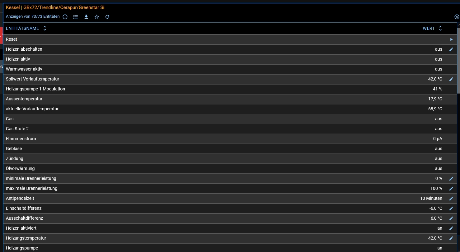
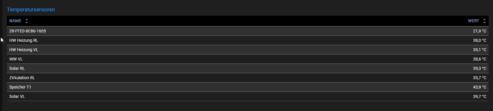
Hallo zusammen,

Ich habe hier den Beitrag jetzt Jahre verfolgt. Und sehr viele Infos
gewonnen.
Danke dafür.

Da mir die ganze Bastelei mit dem PI und den Sensoren zuviel Aufwand
war, habe ich eine kompakte smarte Lösung dazu installiert.
Ein EMS-ESP Gateway auf der Basis des ESP8266. Und was soll ich sagen,
klein kompakt und tut was es soll.
Therme lässt sich jetzt über ein Web-Interface steuern und jetzt kommt
die Anbindung an den IO-Broker.
Anbei mal 2 Bilder welche Werte ich auslesen und schreiben kann, und
welche Sensoren es ausliest.

Vielleicht ist das ja für den einen oder anderen interessant. Die
Anbindung basiert weitestgehend auf die Schaltung hier zurück.
Bernhard D. schrieb:
> Vielleicht ist das ja für den einen oder anderen interessant. Die
> Anbindung basiert weitestgehend auf die Schaltung hier zurück.

Sieht gut aus.
Willst Du das hier oder auf github veröffentlichen?

Gruß Norbert
Angehängte Dateien:
-

Adapterplatine.jpg
220 KB -

Adapterplatine_2.jpg
39 KB
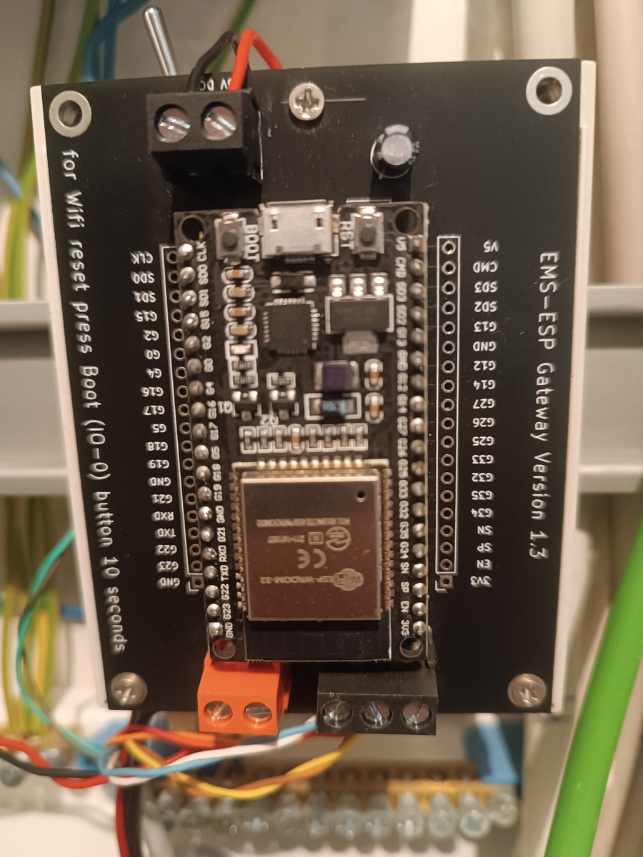
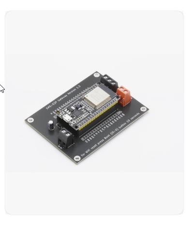
Hallo,

hier ist der aktuelle Beitrag auf Github

https://github.com/emsesp/EMS-ESP32/releases/tag/latest

Ich habe noch die Version 3.6.4 habe aber einen neuen ESP32-S3 den ich
jetzt programmieren werde.
Da kann ich zur Not immer noch den alten Kontroller wieder auf das Board
setzen.
Die Platine habe ich fertig über Ebay bezogen, kostete 50@.
Und das habe ich in ein Hutschienengehäuse eingeschraubt.
hier der aktuelle Link, aber viel zu teuer.

https://www.ebay.de/itm/276135335043
Bitte melde dich an um einen Beitrag zu schreiben. Anmeldung ist kostenlos und dauert nur eine Minute.
Bestehender Account
Schon ein Account bei Google/GoogleMail? Keine Anmeldung erforderlich!
Mit Google-Account einloggen
Mit Google-Account einloggen
Noch kein Account? Hier anmelden.