Hallo,
ich verwende WinAVR zum Programmieren meines ATMEGA16. Daran habe ich
ein günstiges LCD von Pollin (4x27, HD44780) angeschlossen, dazu die
lib von Peter Fleury verwendet.
Das LCD läuft im 4Bit- Modus und funzt einwandfrei.
Jetzt möchte ich aber gerne ein LCD mit Hintergrundbeleuchtung
verwenden. Habe dabei das P161B von www.Peaktech.de im Auge.
Das hat nun aber den KS0076 als Contoller.

Meine Frage ist nun:
Sind HD44780 und KS0076 kompatibel?
Muss ich Änderungen in der lib vornehmen?
Hm....kann die Lib von Peter Fleury nicht anwenden.
Wenn ich nur lcd_init(LCD_DISP_ON_CURSOR_BLINK) angebe dreht mein AVR
Studio4 schon völlig ab.
Es bringt eine ganze Latte von gcc-Fehlermeldungen. WinAVR ist
installiert, also auch der GCC-Compiler....

Woran kann das liegen?
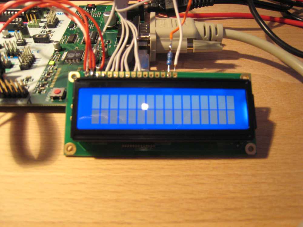
Habe nun das Display angeschlossen und den Code von Peter Fleury
kompiliert.

Das ging alles einwandfrei. Nur das Display zeigt absolut gar nichts an.

Ich habe das STK500 Board und folgendermaßen verkabelt.

Spannungsversorgung von VTG und GND  von PORTC.
Daran das Poti um die Kontrastspannung einzustellen.

Die Spannung für die HIntergrundbeleuchtung hab ich von VTG und GND von
PORTB.

PORTD hab ich mit den Tastern verbunden, da beim Druck auf Taster 2 ja
das Programm weiterlaufen soll.

An PORTA hab ich die PINS 4,5,6 mit den PINS 6,5,4 des LCDs verbunden.
Die Datenpins habe ich an PORTA von Pins 0,1,2,3 an Pins 7,8,9,10 des
LCDs angeschlossen.

Trotzdem geht nix. Hab den Quellcode komplett aus der Lib entnommen.
Nichts dran rumgepfuscht.

Wenn ich den PORTA mit den LEDs auf dem STK500 verbinde geht auch
nichts.... Da leuchten dann LED4 und LED6 und das wars dann auch.

Was mach ich falsch?!

Gruß

der Prkatikant
> Nur das Display zeigt absolut gar nichts an.

Wie, nichts?

Wenn du an das Display nur die Spannungsversorgung
anschliesst und sonst nichts, dann zeigt das Display
in der ersten Zeile einen dunklen Balken an. Hast du
den?


Wenn das Display bei dir also absolut gar nichts anzeigt, dann
* stimmt mit der Spannungsversorgung was nicht
* ist alles in Ordnung und das Display ist initialisiert.
  Der Balken verschwindet bei korrekter Initialisierung
* stimmt die Kontrastspannung nicht

> Nichts dran rumgepfuscht.
Die Konfiguration wirst du ja doch gemacht haben.
Taktfrequenz einstellen und Pinbelegung eintragen.
:-)

> Da leuchten dann LED4 und LED6 und das wars dann auch.
Ausser wenn du sehr gute Augen hast, wird es dir auch
schwerfallen Millisekunden Impulse zu sehen.
Also, das Display leuchtet eben blau (Hintergrundbeleuchtung) und zeigt
2 weiße Zeilen an.

so wie im anhang!
Pinbelegung an PORTA hab ich so übernommen.

Wenn ich nun in der lcd.h aber den PORT ändern will auf PORTB, dann
klappt das nicht. der Simulator im AVR Studio4 zeigt mir dann trotzdem
an, dass alles an PORTA abläuft. Echt komisch.

Die Taktfrequenz ist im SImulator auf 4 MHZ eingetragen, genauso in der
lcd.h als XTAL 4000000

Stimmt daran was nicht?!
> Die Taktfrequenz ist im SImulator auf 4 MHZ eingetragen, genauso in der
> lcd.h als XTAL 4000000

Läuft der µC auch wirklich mit 4 Mhz?
Sprich hast du an den Fuses gespielt?
Wenn nicht, dann läuft der µC immer noch mit 1Mhz.
Sooooolte aber eigentlich keine Rolle spielen. Die
Warteschleifen bei der Initialisierung sind dann zu
lang. Besser zu lang als zu kurz.

> Wenn ich nun in der lcd.h aber den PORT ändern will auf PORTB, dann
> klappt das nicht.

Das klappt schon. Nur musst du alles, inklusive lcd.c, neu
kompilieren.

Hmm.
Philip Kottmann wrote:
> anhang *g*

Das sieht mir so aus, als ob der Kontrast etwas zu hoch
eingestellt ist. Die Kontrastspannung ist meist im unteren
Bereich zu finden, das Poti als fast bis ganz am GND
Endanschlag. Da sollte nur eine weisse Zeile (die erste)
sein.
Angehängte Dateien:
-

IMG_0382_1_.jpg
60 KB
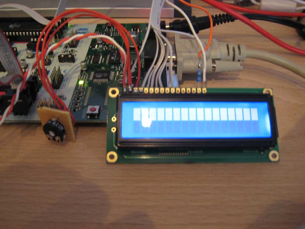
Hab jetzt die Fuses auf

Int. RC Osc. 4MHz; Start-up time 6CK + 64ms

Das Poti hab ich jetzt um etwa 20% heruntergedreht.....
siehe Anhang!

Das Projekt komplett "rebuildet" und reingeladen.

wie man sieht, sieht man nichts.......... heul
Moin!

Also wie in dem Thread Beitrag "Infos über LCD-Display"
irgendwo in der Mitte beschrieben ist, ist der KS0076 zwar
HD44780-kompatibel, benötigt aber eine andere Initialisierung.

Antwort von Marco:
>Aber das Datenblatt zum KS.... brauchst du auch, weil die Initalisierung
>anders ist als beim HD44780.

Vielleicht hilft Dir das weiter.


BTW: Da ich mit dem Gedanken spiele, mir auch so ein Modul zu kaufen,
kannst Du bitte, falls Du Änderungen an der Lib anstellst, diese hier
oder ins Codeforum setzen ;-)
Könnte es sein, dass du die unteren statt die oberen vier Datenleitungen
des Displays angeschlossen hast? Zumindest sieht's im Bild so aus.
Philipp Burch wrote:
> Könnte es sein, dass du die unteren statt die oberen vier Datenleitungen
> des Displays angeschlossen hast? Zumindest sieht's im Bild so aus.

Ja, habe Datenleitung D0-D3 angeschlossen..... so stehts doch in der
lcd.h?!?!
Okay, funktioniert jetzt........Ich programmier ein wenig rum und schau'
dann mal, ob alles tut wie ich will....
Schließt man nicht normalerweise die Pins D4- D7 im 4 bit modus an?

Also ich habe mir nun auch einen LCD Display 4,75mm 204A-CC-BC-3LP
zugelegt und benutze ebenfalls die Lib von Peter Fleury, aber irgendwie
will das LCD nichts anzeigen...???

Das 4x20 LCD zeigt beim Anschalten ohne uC die erste und dritte zeile
als balken an die zweite und vierte bleiben leer.
Beim anschalten mit uC verschwinden die Balken also ist das LCD wohl
richtig initialisiert, aber warum zeigt es nur nichts an wenn ich
1 | lcd_init(LCD_DISP_ON); |
2 | lcd_clrscr(); |
3 | lcd_gotoxy(0,0); |
4 | lcd_puts("---Palutecsystems---"); |
in der main ausführe????

Der Controller KS0076B ist doch kompatibel zu HD44780 oder wo liegt das
Problem?
>Der Controller KS0076B ist doch kompatibel zu HD44780 oder wo liegt das
>Problem?

Dein Controller ist ein KS0066 und der ist kompatibel zu HD44780.

>Schließt man nicht normalerweise die Pins D4- D7 im 4 bit modus an?

Ich denke das ist dein Problem. Wie hast du den angeschlossen?
An welchen uC und bei welcher Taktrate?

PS: Es wird nicht gerne gesehen einen 5 Jahre alten Thread aus dem Grab
zu holen.
Greenhorn schrieb:
> Das 4x20 LCD zeigt beim Anschalten ohne uC die erste und dritte zeile
> als balken an die zweite und vierte bleiben leer.
> Beim anschalten mit uC verschwinden die Balken also ist das LCD wohl
> richtig initialisiert,

Das halte ich für einen Trugschluss. Dieses Verhalten kann auch bei
nicht vollständiger oder fehlerhafter Initialisierung auftreten. Ursache
meist: falsche delays, da der Controller mit anderer Taktfrequenz läuft,
als angenommen.

ABER: Warum muss man für eine derartige Frage einen Thread ausgraben,
der vor fast 7 Jahren eröffnet wurde?
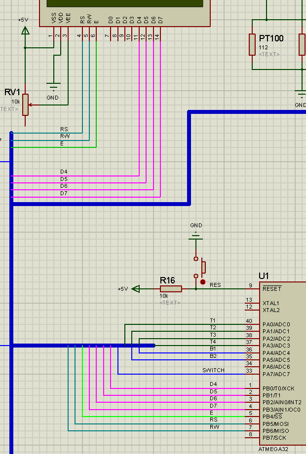
Ja aber ich habe mir in dem Fall gedacht machen wir mal eine Ausnahme,
weil die Beschreibung so gut passt.

Also ich habe Die Pins D4-D7 angeschlossen. Das Programm läuft auf einem
Atmega32 mit einem internen takt von 8MHZ welcher auch in den
Headerdateien definiert ist.
>ABER: Warum muss man für eine derartige Frage einen Thread ausgraben,
>der vor fast 7 Jahren eröffnet wurde?

Upps verrechnet;)

>Also ich habe Die Pins D4-D7 angeschlossen. Das Programm läuft auf einem
>Atmega32 mit einem internen takt von 8MHZ welcher auch in den
>Headerdateien definiert ist.

Programm zeigen und vollständige Pinbelegung zeigen.
Angehängte Dateien:
-

LCDemb.jpg
340 KB
lcd.c
1 | /****************************************************************************
|
2 | Title : HD44780U LCD library
|
3 | Author: Peter Fleury <pfleury@gmx.ch> http://jump.to/fleury
|
4 | File: $Id: lcd.c,v 1.14.2.2 2012/02/12 07:51:00 peter Exp $
|
5 | Software: AVR-GCC 3.3
|
6 | Target: any AVR device, memory mapped mode only for AT90S4414/8515/Mega
|
7 | |
8 | DESCRIPTION
|
9 | Basic routines for interfacing a HD44780U-based text lcd display
|
10 | |
11 | Originally based on Volker Oth's lcd library,
|
12 | changed lcd_init(), added additional constants for lcd_command(),
|
13 | added 4-bit I/O mode, improved and optimized code.
|
14 | |
15 | Library can be operated in memory mapped mode (LCD_IO_MODE=0) or in
|
16 | 4-bit IO port mode (LCD_IO_MODE=1). 8-bit IO port mode not supported.
|
17 |
|
18 | Memory mapped mode compatible with Kanda STK200, but supports also
|
19 | generation of R/W signal through A8 address line.
|
20 | |
21 | USAGE
|
22 | See the C include lcd.h file for a description of each function
|
23 |
|
24 | *****************************************************************************/
|
25 | #include <inttypes.h> |
26 | #include <avr/io.h> |
27 | #include <avr/pgmspace.h> |
28 | #include "lcd.h" |
29 | |
30 | |
31 | |
32 | /*
|
33 | ** constants/macros
|
34 | */
|
35 | #define DDR(x) (*(&x - 1)) /* address of data direction register of port x */ |
36 | #if defined(__AVR_ATmega64__) || defined(__AVR_ATmega128__)
|
37 | /* on ATmega64/128 PINF is on port 0x00 and not 0x60 */
|
38 | #define PIN(x) ( &PORTF==&(x) ? _SFR_IO8(0x00) : (*(&x - 2)) )
|
39 | #else
|
40 | #define PIN(x) (*(&x - 2)) /* address of input register of port x */ |
41 | #endif
|
42 | |
43 | |
44 | #if LCD_IO_MODE
|
45 | #define lcd_e_delay() __asm__ __volatile__( "rjmp 1f\n 1:" ); //#define lcd_e_delay() __asm__ __volatile__( "rjmp 1f\n 1: rjmp 2f\n 2:" );
|
46 | #define lcd_e_high() LCD_E_PORT |= _BV(LCD_E_PIN);
|
47 | #define lcd_e_low() LCD_E_PORT &= ~_BV(LCD_E_PIN);
|
48 | #define lcd_e_toggle() toggle_e()
|
49 | #define lcd_rw_high() LCD_RW_PORT |= _BV(LCD_RW_PIN)
|
50 | #define lcd_rw_low() LCD_RW_PORT &= ~_BV(LCD_RW_PIN)
|
51 | #define lcd_rs_high() LCD_RS_PORT |= _BV(LCD_RS_PIN)
|
52 | #define lcd_rs_low() LCD_RS_PORT &= ~_BV(LCD_RS_PIN)
|
53 | #endif
|
54 | |
55 | #if LCD_IO_MODE
|
56 | #if LCD_LINES==1
|
57 | #define LCD_FUNCTION_DEFAULT LCD_FUNCTION_4BIT_1LINE
|
58 | #else
|
59 | #define LCD_FUNCTION_DEFAULT LCD_FUNCTION_4BIT_2LINES
|
60 | #endif
|
61 | #else
|
62 | #if LCD_LINES==1
|
63 | #define LCD_FUNCTION_DEFAULT LCD_FUNCTION_8BIT_1LINE
|
64 | #else
|
65 | #define LCD_FUNCTION_DEFAULT LCD_FUNCTION_8BIT_2LINES
|
66 | #endif
|
67 | #endif
|
68 | |
69 | #if LCD_CONTROLLER_KS0073
|
70 | #if LCD_LINES==4
|
71 | |
72 | #define KS0073_EXTENDED_FUNCTION_REGISTER_ON 0x2C /* |0|010|1100 4-bit mode, extension-bit RE = 1 */ |
73 | #define KS0073_EXTENDED_FUNCTION_REGISTER_OFF 0x28 /* |0|010|1000 4-bit mode, extension-bit RE = 0 */ |
74 | #define KS0073_4LINES_MODE 0x09 /* |0|000|1001 4 lines mode */ |
75 | |
76 | #endif
|
77 | #endif
|
78 | |
79 | /*
|
80 | ** function prototypes
|
81 | */
|
82 | #if LCD_IO_MODE
|
83 | static void toggle_e(void); |
84 | #endif
|
85 | |
86 | /*
|
87 | ** local functions
|
88 | */
|
89 | |
90 | |
91 | |
92 | /*************************************************************************
|
93 | delay loop for small accurate delays: 16-bit counter, 4 cycles/loop
|
94 | *************************************************************************/
|
95 | static inline void _delayFourCycles(unsigned int __count) |
96 | {
|
97 | if ( __count == 0 ) |
98 | __asm__ __volatile__( "rjmp 1f\n 1:" ); // 2 cycles |
99 | else
|
100 | __asm__ __volatile__ ( |
101 | "1: sbiw %0,1" "\n\t" |
102 | "brne 1b" // 4 cycles/loop |
103 | : "=w" (__count) |
104 | : "0" (__count) |
105 | );
|
106 | }
|
107 | |
108 | |
109 | /*************************************************************************
|
110 | delay for a minimum of <us> microseconds
|
111 | the number of loops is calculated at compile-time from MCU clock frequency
|
112 | *************************************************************************/
|
113 | #define delay(us) _delayFourCycles( ( ( 1*(XTAL/4000) )*us)/1000 )
|
114 | |
115 | |
116 | #if LCD_IO_MODE
|
117 | /* toggle Enable Pin to initiate write */
|
118 | static void toggle_e(void) |
119 | {
|
120 | lcd_e_high(); |
121 | lcd_e_delay(); |
122 | lcd_e_low(); |
123 | }
|
124 | #endif
|
125 | |
126 | |
127 | /*************************************************************************
|
128 | Low-level function to write byte to LCD controller
|
129 | Input: data byte to write to LCD
|
130 | rs 1: write data
|
131 | 0: write instruction
|
132 | Returns: none
|
133 | *************************************************************************/
|
134 | #if LCD_IO_MODE
|
135 | static void lcd_write(uint8_t data,uint8_t rs) |
136 | {
|
137 | unsigned char dataBits ; |
138 | |
139 | |
140 | if (rs) { /* write data (RS=1, RW=0) */ |
141 | lcd_rs_high(); |
142 | } else { /* write instruction (RS=0, RW=0) */ |
143 | lcd_rs_low(); |
144 | }
|
145 | lcd_rw_low(); |
146 | |
147 | if ( ( &LCD_DATA0_PORT == &LCD_DATA1_PORT) && ( &LCD_DATA1_PORT == &LCD_DATA2_PORT ) && ( &LCD_DATA2_PORT == &LCD_DATA3_PORT ) |
148 | && (LCD_DATA0_PIN == 0) && (LCD_DATA1_PIN == 1) && (LCD_DATA2_PIN == 2) && (LCD_DATA3_PIN == 3) ) |
149 | {
|
150 | /* configure data pins as output */
|
151 | DDR(LCD_DATA0_PORT) |= 0x0F; |
152 | |
153 | /* output high nibble first */
|
154 | dataBits = LCD_DATA0_PORT & 0xF0; |
155 | LCD_DATA0_PORT = dataBits |((data>>4)&0x0F); |
156 | lcd_e_toggle(); |
157 | |
158 | /* output low nibble */
|
159 | LCD_DATA0_PORT = dataBits | (data&0x0F); |
160 | lcd_e_toggle(); |
161 | |
162 | /* all data pins high (inactive) */
|
163 | LCD_DATA0_PORT = dataBits | 0x0F; |
164 | }
|
165 | else
|
166 | {
|
167 | /* configure data pins as output */
|
168 | DDR(LCD_DATA0_PORT) |= _BV(LCD_DATA0_PIN); |
169 | DDR(LCD_DATA1_PORT) |= _BV(LCD_DATA1_PIN); |
170 | DDR(LCD_DATA2_PORT) |= _BV(LCD_DATA2_PIN); |
171 | DDR(LCD_DATA3_PORT) |= _BV(LCD_DATA3_PIN); |
172 | |
173 | /* output high nibble first */
|
174 | LCD_DATA3_PORT &= ~_BV(LCD_DATA3_PIN); |
175 | LCD_DATA2_PORT &= ~_BV(LCD_DATA2_PIN); |
176 | LCD_DATA1_PORT &= ~_BV(LCD_DATA1_PIN); |
177 | LCD_DATA0_PORT &= ~_BV(LCD_DATA0_PIN); |
178 | if(data & 0x80) LCD_DATA3_PORT |= _BV(LCD_DATA3_PIN); |
179 | if(data & 0x40) LCD_DATA2_PORT |= _BV(LCD_DATA2_PIN); |
180 | if(data & 0x20) LCD_DATA1_PORT |= _BV(LCD_DATA1_PIN); |
181 | if(data & 0x10) LCD_DATA0_PORT |= _BV(LCD_DATA0_PIN); |
182 | lcd_e_toggle(); |
183 | |
184 | /* output low nibble */
|
185 | LCD_DATA3_PORT &= ~_BV(LCD_DATA3_PIN); |
186 | LCD_DATA2_PORT &= ~_BV(LCD_DATA2_PIN); |
187 | LCD_DATA1_PORT &= ~_BV(LCD_DATA1_PIN); |
188 | LCD_DATA0_PORT &= ~_BV(LCD_DATA0_PIN); |
189 | if(data & 0x08) LCD_DATA3_PORT |= _BV(LCD_DATA3_PIN); |
190 | if(data & 0x04) LCD_DATA2_PORT |= _BV(LCD_DATA2_PIN); |
191 | if(data & 0x02) LCD_DATA1_PORT |= _BV(LCD_DATA1_PIN); |
192 | if(data & 0x01) LCD_DATA0_PORT |= _BV(LCD_DATA0_PIN); |
193 | lcd_e_toggle(); |
194 | |
195 | /* all data pins high (inactive) */
|
196 | LCD_DATA0_PORT |= _BV(LCD_DATA0_PIN); |
197 | LCD_DATA1_PORT |= _BV(LCD_DATA1_PIN); |
198 | LCD_DATA2_PORT |= _BV(LCD_DATA2_PIN); |
199 | LCD_DATA3_PORT |= _BV(LCD_DATA3_PIN); |
200 | }
|
201 | }
|
202 | #else
|
203 | #define lcd_write(d,rs) if (rs) *(volatile uint8_t*)(LCD_IO_DATA) = d; else *(volatile uint8_t*)(LCD_IO_FUNCTION) = d;
|
204 | /* rs==0 -> write instruction to LCD_IO_FUNCTION */
|
205 | /* rs==1 -> write data to LCD_IO_DATA */
|
206 | #endif
|
207 | |
208 | |
209 | /*************************************************************************
|
210 | Low-level function to read byte from LCD controller
|
211 | Input: rs 1: read data
|
212 | 0: read busy flag / address counter
|
213 | Returns: byte read from LCD controller
|
214 | *************************************************************************/
|
215 | #if LCD_IO_MODE
|
216 | static uint8_t lcd_read(uint8_t rs) |
217 | {
|
218 | uint8_t data; |
219 | |
220 | |
221 | if (rs) |
222 | lcd_rs_high(); /* RS=1: read data */ |
223 | else
|
224 | lcd_rs_low(); /* RS=0: read busy flag */ |
225 | lcd_rw_high(); /* RW=1 read mode */ |
226 | |
227 | if ( ( &LCD_DATA0_PORT == &LCD_DATA1_PORT) && ( &LCD_DATA1_PORT == &LCD_DATA2_PORT ) && ( &LCD_DATA2_PORT == &LCD_DATA3_PORT ) |
228 | && ( LCD_DATA0_PIN == 0 )&& (LCD_DATA1_PIN == 1) && (LCD_DATA2_PIN == 2) && (LCD_DATA3_PIN == 3) ) |
229 | {
|
230 | DDR(LCD_DATA0_PORT) &= 0xF0; /* configure data pins as input */ |
231 | |
232 | lcd_e_high(); |
233 | lcd_e_delay(); |
234 | data = PIN(LCD_DATA0_PORT) << 4; /* read high nibble first */ |
235 | lcd_e_low(); |
236 | |
237 | lcd_e_delay(); /* Enable 500ns low */ |
238 | |
239 | lcd_e_high(); |
240 | lcd_e_delay(); |
241 | data |= PIN(LCD_DATA0_PORT)&0x0F; /* read low nibble */ |
242 | lcd_e_low(); |
243 | }
|
244 | else
|
245 | {
|
246 | /* configure data pins as input */
|
247 | DDR(LCD_DATA0_PORT) &= ~_BV(LCD_DATA0_PIN); |
248 | DDR(LCD_DATA1_PORT) &= ~_BV(LCD_DATA1_PIN); |
249 | DDR(LCD_DATA2_PORT) &= ~_BV(LCD_DATA2_PIN); |
250 | DDR(LCD_DATA3_PORT) &= ~_BV(LCD_DATA3_PIN); |
251 | |
252 | /* read high nibble first */
|
253 | lcd_e_high(); |
254 | lcd_e_delay(); |
255 | data = 0; |
256 | if ( PIN(LCD_DATA0_PORT) & _BV(LCD_DATA0_PIN) ) data |= 0x10; |
257 | if ( PIN(LCD_DATA1_PORT) & _BV(LCD_DATA1_PIN) ) data |= 0x20; |
258 | if ( PIN(LCD_DATA2_PORT) & _BV(LCD_DATA2_PIN) ) data |= 0x40; |
259 | if ( PIN(LCD_DATA3_PORT) & _BV(LCD_DATA3_PIN) ) data |= 0x80; |
260 | lcd_e_low(); |
261 | |
262 | lcd_e_delay(); /* Enable 500ns low */ |
263 | |
264 | /* read low nibble */
|
265 | lcd_e_high(); |
266 | lcd_e_delay(); |
267 | if ( PIN(LCD_DATA0_PORT) & _BV(LCD_DATA0_PIN) ) data |= 0x01; |
268 | if ( PIN(LCD_DATA1_PORT) & _BV(LCD_DATA1_PIN) ) data |= 0x02; |
269 | if ( PIN(LCD_DATA2_PORT) & _BV(LCD_DATA2_PIN) ) data |= 0x04; |
270 | if ( PIN(LCD_DATA3_PORT) & _BV(LCD_DATA3_PIN) ) data |= 0x08; |
271 | lcd_e_low(); |
272 | }
|
273 | return data; |
274 | }
|
275 | #else
|
276 | #define lcd_read(rs) (rs) ? *(volatile uint8_t*)(LCD_IO_DATA+LCD_IO_READ) : *(volatile uint8_t*)(LCD_IO_FUNCTION+LCD_IO_READ)
|
277 | /* rs==0 -> read instruction from LCD_IO_FUNCTION */
|
278 | /* rs==1 -> read data from LCD_IO_DATA */
|
279 | #endif
|
280 | |
281 | |
282 | /*************************************************************************
|
283 | loops while lcd is busy, returns address counter
|
284 | *************************************************************************/
|
285 | static uint8_t lcd_waitbusy(void) |
286 | |
287 | {
|
288 | register uint8_t c; |
289 | |
290 | /* wait until busy flag is cleared */
|
291 | while ( (c=lcd_read(0)) & (1<<LCD_BUSY)) {} |
292 | |
293 | /* the address counter is updated 4us after the busy flag is cleared */
|
294 | delay(2); |
295 | |
296 | /* now read the address counter */
|
297 | return (lcd_read(0)); // return address counter |
298 | |
299 | }/* lcd_waitbusy */ |
300 | |
301 | |
302 | /*************************************************************************
|
303 | Move cursor to the start of next line or to the first line if the cursor
|
304 | is already on the last line.
|
305 | *************************************************************************/
|
306 | static inline void lcd_newline(uint8_t pos) |
307 | {
|
308 | register uint8_t addressCounter; |
309 | |
310 | |
311 | #if LCD_LINES==1
|
312 | addressCounter = 0; |
313 | #endif
|
314 | #if LCD_LINES==2
|
315 | if ( pos < (LCD_START_LINE2) ) |
316 | addressCounter = LCD_START_LINE2; |
317 | else
|
318 | addressCounter = LCD_START_LINE1; |
319 | #endif
|
320 | #if LCD_LINES==4
|
321 | #if KS0073_4LINES_MODE
|
322 | if ( pos < LCD_START_LINE2 ) |
323 | addressCounter = LCD_START_LINE2; |
324 | else if ( (pos >= LCD_START_LINE2) && (pos < LCD_START_LINE3) ) |
325 | addressCounter = LCD_START_LINE3; |
326 | else if ( (pos >= LCD_START_LINE3) && (pos < LCD_START_LINE4) ) |
327 | addressCounter = LCD_START_LINE4; |
328 | else
|
329 | addressCounter = LCD_START_LINE1; |
330 | #else
|
331 | if ( pos < LCD_START_LINE3 ) |
332 | addressCounter = LCD_START_LINE2; |
333 | else if ( (pos >= LCD_START_LINE2) && (pos < LCD_START_LINE4) ) |
334 | addressCounter = LCD_START_LINE3; |
335 | else if ( (pos >= LCD_START_LINE3) && (pos < LCD_START_LINE2) ) |
336 | addressCounter = LCD_START_LINE4; |
337 | else
|
338 | addressCounter = LCD_START_LINE1; |
339 | #endif
|
340 | #endif
|
341 | lcd_command((1<<LCD_DDRAM)+addressCounter); |
342 | |
343 | }/* lcd_newline */ |
344 | |
345 | |
346 | /*
|
347 | ** PUBLIC FUNCTIONS
|
348 | */
|
349 | |
350 | /*************************************************************************
|
351 | Send LCD controller instruction command
|
352 | Input: instruction to send to LCD controller, see HD44780 data sheet
|
353 | Returns: none
|
354 | *************************************************************************/
|
355 | void lcd_command(uint8_t cmd) |
356 | {
|
357 | lcd_waitbusy(); |
358 | lcd_write(cmd,0); |
359 | }
|
360 | |
361 | |
362 | /*************************************************************************
|
363 | Send data byte to LCD controller
|
364 | Input: data to send to LCD controller, see HD44780 data sheet
|
365 | Returns: none
|
366 | *************************************************************************/
|
367 | void lcd_data(uint8_t data) |
368 | {
|
369 | lcd_waitbusy(); |
370 | lcd_write(data,1); |
371 | }
|
372 | |
373 | |
374 | |
375 | /*************************************************************************
|
376 | Set cursor to specified position
|
377 | Input: x horizontal position (0: left most position)
|
378 | y vertical position (0: first line)
|
379 | Returns: none
|
380 | *************************************************************************/
|
381 | void lcd_gotoxy(uint8_t x, uint8_t y) |
382 | {
|
383 | #if LCD_LINES==1
|
384 | lcd_command((1<<LCD_DDRAM)+LCD_START_LINE1+x); |
385 | #endif
|
386 | #if LCD_LINES==2
|
387 | if ( y==0 ) |
388 | lcd_command((1<<LCD_DDRAM)+LCD_START_LINE1+x); |
389 | else
|
390 | lcd_command((1<<LCD_DDRAM)+LCD_START_LINE2+x); |
391 | #endif
|
392 | #if LCD_LINES==4
|
393 | if ( y==0 ) |
394 | lcd_command((1<<LCD_DDRAM)+LCD_START_LINE1+x); |
395 | else if ( y==1) |
396 | lcd_command((1<<LCD_DDRAM)+LCD_START_LINE2+x); |
397 | else if ( y==2) |
398 | lcd_command((1<<LCD_DDRAM)+LCD_START_LINE3+x); |
399 | else /* y==3 */ |
400 | lcd_command((1<<LCD_DDRAM)+LCD_START_LINE4+x); |
401 | #endif
|
402 | |
403 | }/* lcd_gotoxy */ |
404 | |
405 | |
406 | /*************************************************************************
|
407 | *************************************************************************/
|
408 | int lcd_getxy(void) |
409 | {
|
410 | return lcd_waitbusy(); |
411 | }
|
412 | |
413 | |
414 | /*************************************************************************
|
415 | Clear display and set cursor to home position
|
416 | *************************************************************************/
|
417 | void lcd_clrscr(void) |
418 | {
|
419 | lcd_command(1<<LCD_CLR); |
420 | }
|
421 | |
422 | |
423 | /*************************************************************************
|
424 | Set cursor to home position
|
425 | *************************************************************************/
|
426 | void lcd_home(void) |
427 | {
|
428 | lcd_command(1<<LCD_HOME); |
429 | }
|
430 | |
431 | |
432 | /*************************************************************************
|
433 | Display character at current cursor position
|
434 | Input: character to be displayed
|
435 | Returns: none
|
436 | *************************************************************************/
|
437 | void lcd_putc(char c) |
438 | {
|
439 | uint8_t pos; |
440 | |
441 | |
442 | pos = lcd_waitbusy(); // read busy-flag and address counter |
443 | if (c=='\n') |
444 | {
|
445 | lcd_newline(pos); |
446 | }
|
447 | else
|
448 | {
|
449 | #if LCD_WRAP_LINES==1
|
450 | #if LCD_LINES==1
|
451 | if ( pos == LCD_START_LINE1+LCD_DISP_LENGTH ) { |
452 | lcd_write((1<<LCD_DDRAM)+LCD_START_LINE1,0); |
453 | }
|
454 | #elif LCD_LINES==2
|
455 | if ( pos == LCD_START_LINE1+LCD_DISP_LENGTH ) { |
456 | lcd_write((1<<LCD_DDRAM)+LCD_START_LINE2,0); |
457 | }else if ( pos == LCD_START_LINE2+LCD_DISP_LENGTH ){ |
458 | lcd_write((1<<LCD_DDRAM)+LCD_START_LINE1,0); |
459 | }
|
460 | #elif LCD_LINES==4
|
461 | if ( pos == LCD_START_LINE1+LCD_DISP_LENGTH ) { |
462 | lcd_write((1<<LCD_DDRAM)+LCD_START_LINE2,0); |
463 | }else if ( pos == LCD_START_LINE2+LCD_DISP_LENGTH ) { |
464 | lcd_write((1<<LCD_DDRAM)+LCD_START_LINE3,0); |
465 | }else if ( pos == LCD_START_LINE3+LCD_DISP_LENGTH ) { |
466 | lcd_write((1<<LCD_DDRAM)+LCD_START_LINE4,0); |
467 | }else if ( pos == LCD_START_LINE4+LCD_DISP_LENGTH ) { |
468 | lcd_write((1<<LCD_DDRAM)+LCD_START_LINE1,0); |
469 | }
|
470 | #endif
|
471 | lcd_waitbusy(); |
472 | #endif
|
473 | lcd_write(c, 1); |
474 | }
|
475 | |
476 | }/* lcd_putc */ |
477 | |
478 | |
479 | /*************************************************************************
|
480 | Display string without auto linefeed
|
481 | Input: string to be displayed
|
482 | Returns: none
|
483 | *************************************************************************/
|
484 | void lcd_puts(const char *s) |
485 | /* print string on lcd (no auto linefeed) */
|
486 | {
|
487 | register char c; |
488 | |
489 | while ( (c = *s++) ) { |
490 | lcd_putc(c); |
491 | }
|
492 | |
493 | }/* lcd_puts */ |
494 | |
495 | |
496 | /*************************************************************************
|
497 | Display string from program memory without auto linefeed
|
498 | Input: string from program memory be be displayed
|
499 | Returns: none
|
500 | *************************************************************************/
|
501 | void lcd_puts_p(const char *progmem_s) |
502 | /* print string from program memory on lcd (no auto linefeed) */
|
503 | {
|
504 | register char c; |
505 | |
506 | while ( (c = pgm_read_byte(progmem_s++)) ) { |
507 | lcd_putc(c); |
508 | }
|
509 | |
510 | }/* lcd_puts_p */ |
511 | |
512 | |
513 | /*************************************************************************
|
514 | Initialize display and select type of cursor
|
515 | Input: dispAttr LCD_DISP_OFF display off
|
516 | LCD_DISP_ON display on, cursor off
|
517 | LCD_DISP_ON_CURSOR display on, cursor on
|
518 | LCD_DISP_CURSOR_BLINK display on, cursor on flashing
|
519 | Returns: none
|
520 | *************************************************************************/
|
521 | void lcd_init(uint8_t dispAttr) |
522 | {
|
523 | #if LCD_IO_MODE
|
524 | /*
|
525 | * Initialize LCD to 4 bit I/O mode
|
526 | */
|
527 | |
528 | if ( ( &LCD_DATA0_PORT == &LCD_DATA1_PORT) && ( &LCD_DATA1_PORT == &LCD_DATA2_PORT ) && ( &LCD_DATA2_PORT == &LCD_DATA3_PORT ) |
529 | && ( &LCD_RS_PORT == &LCD_DATA0_PORT) && ( &LCD_RW_PORT == &LCD_DATA0_PORT) && (&LCD_E_PORT == &LCD_DATA0_PORT) |
530 | && (LCD_DATA0_PIN == 0 ) && (LCD_DATA1_PIN == 1) && (LCD_DATA2_PIN == 2) && (LCD_DATA3_PIN == 3) |
531 | && (LCD_RS_PIN == 4 ) && (LCD_RW_PIN == 5) && (LCD_E_PIN == 6 ) ) |
532 | {
|
533 | /* configure all port bits as output (all LCD lines on same port) */
|
534 | DDR(LCD_DATA0_PORT) |= 0x7F; |
535 | }
|
536 | else if ( ( &LCD_DATA0_PORT == &LCD_DATA1_PORT) && ( &LCD_DATA1_PORT == &LCD_DATA2_PORT ) && ( &LCD_DATA2_PORT == &LCD_DATA3_PORT ) |
537 | && (LCD_DATA0_PIN == 0 ) && (LCD_DATA1_PIN == 1) && (LCD_DATA2_PIN == 2) && (LCD_DATA3_PIN == 3) ) |
538 | {
|
539 | /* configure all port bits as output (all LCD data lines on same port, but control lines on different ports) */
|
540 | DDR(LCD_DATA0_PORT) |= 0x0F; |
541 | DDR(LCD_RS_PORT) |= _BV(LCD_RS_PIN); |
542 | DDR(LCD_RW_PORT) |= _BV(LCD_RW_PIN); |
543 | DDR(LCD_E_PORT) |= _BV(LCD_E_PIN); |
544 | }
|
545 | else
|
546 | {
|
547 | /* configure all port bits as output (LCD data and control lines on different ports */
|
548 | DDR(LCD_RS_PORT) |= _BV(LCD_RS_PIN); |
549 | DDR(LCD_RW_PORT) |= _BV(LCD_RW_PIN); |
550 | DDR(LCD_E_PORT) |= _BV(LCD_E_PIN); |
551 | DDR(LCD_DATA0_PORT) |= _BV(LCD_DATA0_PIN); |
552 | DDR(LCD_DATA1_PORT) |= _BV(LCD_DATA1_PIN); |
553 | DDR(LCD_DATA2_PORT) |= _BV(LCD_DATA2_PIN); |
554 | DDR(LCD_DATA3_PORT) |= _BV(LCD_DATA3_PIN); |
555 | }
|
556 | delay(16000); /* wait 16ms or more after power-on */ |
557 | |
558 | /* initial write to lcd is 8bit */
|
559 | LCD_DATA1_PORT |= _BV(LCD_DATA1_PIN); // _BV(LCD_FUNCTION)>>4; |
560 | LCD_DATA0_PORT |= _BV(LCD_DATA0_PIN); // _BV(LCD_FUNCTION_8BIT)>>4; |
561 | lcd_e_toggle(); |
562 | delay(4992); /* delay, busy flag can't be checked here */ |
563 | |
564 | /* repeat last command */
|
565 | lcd_e_toggle(); |
566 | delay(64); /* delay, busy flag can't be checked here */ |
567 | |
568 | /* repeat last command a third time */
|
569 | lcd_e_toggle(); |
570 | delay(64); /* delay, busy flag can't be checked here */ |
571 | |
572 | /* now configure for 4bit mode */
|
573 | LCD_DATA0_PORT &= ~_BV(LCD_DATA0_PIN); // LCD_FUNCTION_4BIT_1LINE>>4 |
574 | lcd_e_toggle(); |
575 | delay(64); /* some displays need this additional delay */ |
576 | |
577 | /* from now the LCD only accepts 4 bit I/O, we can use lcd_command() */
|
578 | #else
|
579 | /*
|
580 | * Initialize LCD to 8 bit memory mapped mode
|
581 | */
|
582 | |
583 | /* enable external SRAM (memory mapped lcd) and one wait state */
|
584 | MCUCR = _BV(SRE) | _BV(SRW); |
585 | |
586 | /* reset LCD */
|
587 | delay(16000); /* wait 16ms after power-on */ |
588 | lcd_write(LCD_FUNCTION_8BIT_1LINE,0); /* function set: 8bit interface */ |
589 | delay(4992); /* wait 5ms */ |
590 | lcd_write(LCD_FUNCTION_8BIT_1LINE,0); /* function set: 8bit interface */ |
591 | delay(64); /* wait 64us */ |
592 | lcd_write(LCD_FUNCTION_8BIT_1LINE,0); /* function set: 8bit interface */ |
593 | delay(64); /* wait 64us */ |
594 | #endif
|
595 | |
596 | #if KS0073_4LINES_MODE
|
597 | /* Display with KS0073 controller requires special commands for enabling 4 line mode */
|
598 | lcd_command(KS0073_EXTENDED_FUNCTION_REGISTER_ON); |
599 | lcd_command(KS0073_4LINES_MODE); |
600 | lcd_command(KS0073_EXTENDED_FUNCTION_REGISTER_OFF); |
601 | #else
|
602 | lcd_command(LCD_FUNCTION_DEFAULT); /* function set: display lines */ |
603 | #endif
|
604 | lcd_command(LCD_DISP_OFF); /* display off */ |
605 | lcd_clrscr(); /* display clear */ |
606 | lcd_command(LCD_MODE_DEFAULT); /* set entry mode */ |
607 | lcd_command(dispAttr); /* display/cursor control */ |
608 | |
609 | }/* lcd_init */ |
lcd.h
1 | #ifndef LCD_H
|
2 | #define LCD_H
|
3 | /*************************************************************************
|
4 | Title : C include file for the HD44780U LCD library (lcd.c)
|
5 | Author: Peter Fleury <pfleury@gmx.ch> http://jump.to/fleury
|
6 | File: $Id: lcd.h,v 1.13.2.2 2006/01/30 19:51:33 peter Exp $
|
7 | Software: AVR-GCC 3.3
|
8 | Hardware: any AVR device, memory mapped mode only for AT90S4414/8515/Mega
|
9 | ***************************************************************************/
|
10 | |
11 | /**
|
12 | @defgroup pfleury_lcd LCD library
|
13 | @code #include <lcd.h> @endcode
|
14 |
|
15 | @brief Basic routines for interfacing a HD44780U-based text LCD display
|
16 | |
17 | Originally based on Volker Oth's LCD library,
|
18 | changed lcd_init(), added additional constants for lcd_command(),
|
19 | added 4-bit I/O mode, improved and optimized code.
|
20 |
|
21 | Library can be operated in memory mapped mode (LCD_IO_MODE=0) or in
|
22 | 4-bit IO port mode (LCD_IO_MODE=1). 8-bit IO port mode not supported.
|
23 | |
24 | Memory mapped mode compatible with Kanda STK200, but supports also
|
25 | generation of R/W signal through A8 address line.
|
26 |
|
27 | @author Peter Fleury pfleury@gmx.ch http://jump.to/fleury
|
28 |
|
29 | |
30 | |
31 | */
|
32 | |
33 | /*@{*/
|
34 | |
35 | #if (__GNUC__ * 100 + __GNUC_MINOR__) < 303
|
36 | #error "This library requires AVR-GCC 3.3 or later, update to newer AVR-GCC compiler !"
|
37 | #endif
|
38 | |
39 | #include <inttypes.h> |
40 | #include <avr/pgmspace.h> |
41 | |
42 | /**
|
43 | * @name Definitions for MCU Clock Frequency
|
44 | * Adapt the MCU clock frequency in Hz to your target.
|
45 | */
|
46 | #define XTAL 8000000 /**< clock frequency in Hz, used to calculate delay timer */ |
47 | |
48 | |
49 | /**
|
50 | * @name Definition for LCD controller type
|
51 | * Use 0 for HD44780 controller, change to 1 for displays with KS0073 controller.
|
52 | */
|
53 | #define LCD_CONTROLLER_KS0073 0 /**< Use 0 for HD44780 controller, 1 for KS0073 controller */ |
54 | |
55 | /**
|
56 | * @name Definitions for Display Size
|
57 | * Change these definitions to adapt setting to your display
|
58 | */
|
59 | #define LCD_LINES 4 /**< number of visible lines of the display */ |
60 | #define LCD_DISP_LENGTH 20 /**< visibles characters per line of the display */ |
61 | #define LCD_LINE_LENGTH 0x40 /**< internal line length of the display */ |
62 | #define LCD_START_LINE1 0x00 /**< DDRAM address of first char of line 1 */ |
63 | #define LCD_START_LINE2 0x40 /**< DDRAM address of first char of line 2 */ |
64 | #define LCD_START_LINE3 0x14 /**< DDRAM address of first char of line 3 */ |
65 | #define LCD_START_LINE4 0x54 /**< DDRAM address of first char of line 4 */ |
66 | #define LCD_WRAP_LINES 0 /**< 0: no wrap, 1: wrap at end of visibile line */ |
67 | |
68 | |
69 | #define LCD_IO_MODE 1 /**< 0: memory mapped mode, 1: IO port mode */ |
70 | #if LCD_IO_MODE
|
71 | /**
|
72 | * @name Definitions for 4-bit IO mode
|
73 | * Change LCD_PORT if you want to use a different port for the LCD pins.
|
74 | *
|
75 | * The four LCD data lines and the three control lines RS, RW, E can be on the
|
76 | * same port or on different ports.
|
77 | * Change LCD_RS_PORT, LCD_RW_PORT, LCD_E_PORT if you want the control lines on
|
78 | * different ports.
|
79 | *
|
80 | * Normally the four data lines should be mapped to bit 0..3 on one port, but it
|
81 | * is possible to connect these data lines in different order or even on different
|
82 | * ports by adapting the LCD_DATAx_PORT and LCD_DATAx_PIN definitions.
|
83 | *
|
84 | */
|
85 | #define LCD_PORT PORTB /**< port for the LCD lines */ |
86 | #define LCD_DATA0_PORT LCD_PORT /**< port for 4bit data bit 0 */ |
87 | #define LCD_DATA1_PORT LCD_PORT /**< port for 4bit data bit 1 */ |
88 | #define LCD_DATA2_PORT LCD_PORT /**< port for 4bit data bit 2 */ |
89 | #define LCD_DATA3_PORT LCD_PORT /**< port for 4bit data bit 3 */ |
90 | #define LCD_DATA0_PIN 0 /**< pin for 4bit data bit 0 */ |
91 | #define LCD_DATA1_PIN 1 /**< pin for 4bit data bit 1 */ |
92 | #define LCD_DATA2_PIN 2 /**< pin for 4bit data bit 2 */ |
93 | #define LCD_DATA3_PIN 3 /**< pin for 4bit data bit 3 */ |
94 | #define LCD_RS_PORT LCD_PORT /**< port for RS line */ |
95 | #define LCD_RS_PIN 5 /**< pin for RS line */ |
96 | #define LCD_RW_PORT LCD_PORT /**< port for RW line */ |
97 | #define LCD_RW_PIN 6 /**< pin for RW line */ |
98 | #define LCD_E_PORT LCD_PORT /**< port for Enable line */ |
99 | #define LCD_E_PIN 4 /**< pin for Enable line */ |
100 | |
101 | #elif defined(__AVR_AT90S4414__) || defined(__AVR_AT90S8515__) || defined(__AVR_ATmega64__) || \
|
102 | defined(__AVR_ATmega8515__)|| defined(__AVR_ATmega103__) || defined(__AVR_ATmega128__) || \
|
103 | defined(__AVR_ATmega161__) || defined(__AVR_ATmega162__)
|
104 | /*
|
105 | * memory mapped mode is only supported when the device has an external data memory interface
|
106 | */
|
107 | #define LCD_IO_DATA 0xC000 /* A15=E=1, A14=RS=1 */ |
108 | #define LCD_IO_FUNCTION 0x8000 /* A15=E=1, A14=RS=0 */ |
109 | #define LCD_IO_READ 0x0100 /* A8 =R/W=1 (R/W: 1=Read, 0=Write */ |
110 | #else
|
111 | #error "external data memory interface not available for this device, use 4-bit IO port mode"
|
112 | |
113 | #endif
|
114 | |
115 | |
116 | /**
|
117 | * @name Definitions for LCD command instructions
|
118 | * The constants define the various LCD controller instructions which can be passed to the
|
119 | * function lcd_command(), see HD44780 data sheet for a complete description.
|
120 | */
|
121 | |
122 | /* instruction register bit positions, see HD44780U data sheet */
|
123 | #define LCD_CLR 0 /* DB0: clear display */ |
124 | #define LCD_HOME 1 /* DB1: return to home position */ |
125 | #define LCD_ENTRY_MODE 2 /* DB2: set entry mode */ |
126 | #define LCD_ENTRY_INC 1 /* DB1: 1=increment, 0=decrement */ |
127 | #define LCD_ENTRY_SHIFT 0 /* DB2: 1=display shift on */ |
128 | #define LCD_ON 3 /* DB3: turn lcd/cursor on */ |
129 | #define LCD_ON_DISPLAY 2 /* DB2: turn display on */ |
130 | #define LCD_ON_CURSOR 1 /* DB1: turn cursor on */ |
131 | #define LCD_ON_BLINK 0 /* DB0: blinking cursor ? */ |
132 | #define LCD_MOVE 4 /* DB4: move cursor/display */ |
133 | #define LCD_MOVE_DISP 3 /* DB3: move display (0-> cursor) ? */ |
134 | #define LCD_MOVE_RIGHT 2 /* DB2: move right (0-> left) ? */ |
135 | #define LCD_FUNCTION 5 /* DB5: function set */ |
136 | #define LCD_FUNCTION_8BIT 4 /* DB4: set 8BIT mode (0->4BIT mode) */ |
137 | #define LCD_FUNCTION_2LINES 3 /* DB3: two lines (0->one line) */ |
138 | #define LCD_FUNCTION_10DOTS 2 /* DB2: 5x10 font (0->5x7 font) */ |
139 | #define LCD_CGRAM 6 /* DB6: set CG RAM address */ |
140 | #define LCD_DDRAM 7 /* DB7: set DD RAM address */ |
141 | #define LCD_BUSY 7 /* DB7: LCD is busy */ |
142 | |
143 | /* set entry mode: display shift on/off, dec/inc cursor move direction */
|
144 | #define LCD_ENTRY_DEC 0x04 /* display shift off, dec cursor move dir */ |
145 | #define LCD_ENTRY_DEC_SHIFT 0x05 /* display shift on, dec cursor move dir */ |
146 | #define LCD_ENTRY_INC_ 0x06 /* display shift off, inc cursor move dir */ |
147 | #define LCD_ENTRY_INC_SHIFT 0x07 /* display shift on, inc cursor move dir */ |
148 | |
149 | /* display on/off, cursor on/off, blinking char at cursor position */
|
150 | #define LCD_DISP_OFF 0x08 /* display off */ |
151 | #define LCD_DISP_ON 0x0C /* display on, cursor off */ |
152 | #define LCD_DISP_ON_BLINK 0x0D /* display on, cursor off, blink char */ |
153 | #define LCD_DISP_ON_CURSOR 0x0E /* display on, cursor on */ |
154 | #define LCD_DISP_ON_CURSOR_BLINK 0x0F /* display on, cursor on, blink char */ |
155 | |
156 | /* move cursor/shift display */
|
157 | #define LCD_MOVE_CURSOR_LEFT 0x10 /* move cursor left (decrement) */ |
158 | #define LCD_MOVE_CURSOR_RIGHT 0x14 /* move cursor right (increment) */ |
159 | #define LCD_MOVE_DISP_LEFT 0x18 /* shift display left */ |
160 | #define LCD_MOVE_DISP_RIGHT 0x1C /* shift display right */ |
161 | |
162 | /* function set: set interface data length and number of display lines */
|
163 | #define LCD_FUNCTION_4BIT_1LINE 0x20 /* 4-bit interface, single line, 5x7 dots */ |
164 | #define LCD_FUNCTION_4BIT_2LINES 0x28 /* 4-bit interface, dual line, 5x7 dots */ |
165 | #define LCD_FUNCTION_8BIT_1LINE 0x30 /* 8-bit interface, single line, 5x7 dots */ |
166 | #define LCD_FUNCTION_8BIT_2LINES 0x38 /* 8-bit interface, dual line, 5x7 dots */ |
167 | |
168 | |
169 | #define LCD_MODE_DEFAULT ((1<<LCD_ENTRY_MODE) | (1<<LCD_ENTRY_INC) )
|
170 | |
171 | |
172 | |
173 | /**
|
174 | * @name Functions
|
175 | */
|
176 | |
177 | |
178 | /**
|
179 | @brief Initialize display and select type of cursor
|
180 | @param dispAttr \b LCD_DISP_OFF display off\n
|
181 | \b LCD_DISP_ON display on, cursor off\n
|
182 | \b LCD_DISP_ON_CURSOR display on, cursor on\n
|
183 | \b LCD_DISP_ON_CURSOR_BLINK display on, cursor on flashing
|
184 | @return none
|
185 | */
|
186 | extern void lcd_init(uint8_t dispAttr); |
187 | |
188 | |
189 | /**
|
190 | @brief Clear display and set cursor to home position
|
191 | @param void
|
192 | @return none
|
193 | */
|
194 | extern void lcd_clrscr(void); |
195 | |
196 | |
197 | /**
|
198 | @brief Set cursor to home position
|
199 | @param void
|
200 | @return none
|
201 | */
|
202 | extern void lcd_home(void); |
203 | |
204 | |
205 | /**
|
206 | @brief Set cursor to specified position
|
207 |
|
208 | @param x horizontal position\n (0: left most position)
|
209 | @param y vertical position\n (0: first line)
|
210 | @return none
|
211 | */
|
212 | extern void lcd_gotoxy(uint8_t x, uint8_t y); |
213 | |
214 | |
215 | /**
|
216 | @brief Display character at current cursor position
|
217 | @param c character to be displayed
|
218 | @return none
|
219 | */
|
220 | extern void lcd_putc(char c); |
221 | |
222 | |
223 | /**
|
224 | @brief Display string without auto linefeed
|
225 | @param s string to be displayed
|
226 | @return none
|
227 | */
|
228 | extern void lcd_puts(const char *s); |
229 | |
230 | |
231 | /**
|
232 | @brief Display string from program memory without auto linefeed
|
233 | @param s string from program memory be be displayed
|
234 | @return none
|
235 | @see lcd_puts_P
|
236 | */
|
237 | extern void lcd_puts_p(const char *progmem_s); |
238 | |
239 | |
240 | /**
|
241 | @brief Send LCD controller instruction command
|
242 | @param cmd instruction to send to LCD controller, see HD44780 data sheet
|
243 | @return none
|
244 | */
|
245 | extern void lcd_command(uint8_t cmd); |
246 | |
247 | |
248 | /**
|
249 | @brief Send data byte to LCD controller
|
250 |
|
251 | Similar to lcd_putc(), but without interpreting LF
|
252 | @param data byte to send to LCD controller, see HD44780 data sheet
|
253 | @return none
|
254 | */
|
255 | extern void lcd_data(uint8_t data); |
256 | |
257 | |
258 | /**
|
259 | @brief macros for automatically storing string constant in program memory
|
260 | */
|
261 | #define lcd_puts_P(__s) lcd_puts_p(PSTR(__s))
|
262 | |
263 | /*@}*/
|
264 | #endif //LCD_H
|
main.c
1 | int main(void) |
2 | {
|
3 | |
4 | //Globale Interrupts einschalten
|
5 | sei(); |
6 | /*---------------------------------------------------------------------------------------------------*/
|
7 | //Starten der DCF77 Uhr
|
8 | Start_Clock(); |
9 | /*---------------------------------------------------------------------------------------------------*/
|
10 | |
11 | |
12 | /* initialize display, cursor off */
|
13 | lcd_init(LCD_DISP_ON); |
14 | |
15 | /*-------------------------------------------------------------------------------------------------1*/
|
16 | |
17 | lcd_clrscr(); |
18 | lcd_gotoxy(0,0); |
19 | lcd_puts("---Palutecsystems---"); |
20 | |
21 | |
22 | |
23 | for (;;) { |
24 | |
25 | |
26 | }
|
27 | }
|
Joa der is hardwaremäßig drann nur nicht auf dem Schaltplan sry. Die
includes und sonstiges in der main fehlt auch is nur die Hauptfunktion.
Greenhorn schrieb:
> lcd.c

Hast du irgendeine Vorstellung, wozu es hier im Forum die Funktion
"Dateianhang" gibt?

Denk mal über Sinn und Handlichkeit deines mehr als 900 Zeilen langen
Beitrags nach. Da hätte nur noch gefehlt, das du das Bild als Hexdump
postest.
Oh entschuldigen Sie bitte vielmals... beim nächsten mal gibts ne rar
Datei.
Hi

>Da hätte nur noch gefehlt, das du das Bild als Hexdump
>postest.

Wäre kürzer und übersichtlicher.

MfG Spess
>Kannste mal den Sourcecode davon posten?

Nö, ausprobieren;) Vieleicht später.

Ich hab deine Pinbelegung eingegeben, deinen Controller
ins makefile eingetippt und deinen uC Takt.

Vergiss die erste HEX Datei. Das wird nicht gehen.
Habe es jetzt ganz simpel ohne schnickschnack...
1. Ports definiert
2. Freq. definiert
3. Makefile erstellt
4. uC programmiert

Es funktioniert jedoch einfach nicht...

Habe auch nochmal alle leitungen vom chip zum LCD durchgeklingelt und
bin langsam am verzweifeln :-(
Ich habe nun die Routines aus dem GCC-Tutorial genommen und
ummodifiziert.
Sprich Delays,Commands, Ports, und die init...

Ich denke auch das dass Display richtig initialisiert ist, da ich den
Coursor sichtbar und blinkend wie im Programm eingestellt auf dem LCD
habe.
Die Verkabelung ist der Headerdatei zu entnehmen.

Jedoch bekomme ich leider immer noch keinen Text ausgegeben.
Kennt jemand das LCD Display 4,75mm 204A-CC-BC-3LP von RS und hatte
damit auch Probleme?

Ebenfalls habe ich aus der Codesammlung einen modifizierten Sourcecode
für 0066 Controller ausprobiert doch leider vergeblich.


Kann mir jemand vielleicht noch nen Tipp geben?

Vielen Dank im vorraus.
In der ISIS simu läufts. Kann ich eine Hex datei direkt ohne elf Datei
auf den uC laden? Das hat nämlich gestern nicht geklappt. Benutze
WINAVR.
THX.
Angehängte Dateien:
-

Nerviges_Display.gif
22 KB
Habe es nun geschafft das 4x20 Display 204A-CC-BC-3LP von "RS" mit einem
Atmega32 mithilfe des GCC Tutorials zu initialisieren.

Folgende anpassungen musste ich dazu durchführen:
-Takt, Ports, delays und ändern der Ram Adressen in der Headerfile.
-Die Funktion lcd_init leicht umschreiben wegen der etwas anderen
Initialisierung gegenüber dem Handelsüblichen HD Controller.
1 | void lcd_init( void ) |
2 | {
|
3 | // verwendete Pins auf Ausgang schalten
|
4 | uint8_t pins = (0x0F << LCD_DB) | // 4 Datenleitungen |
5 | (1<<LCD_RS) | // R/S Leitung |
6 | (1<<LCD_EN); // Enable Leitung |
7 | LCD_DDR |= pins; |
8 | |
9 | // initial alle Ausgänge auf Null
|
10 | LCD_PORT &= ~pins; |
11 | |
12 | // warten auf die Bereitschaft des LCD
|
13 | _delay_ms( LCD_BOOTUP_MS ); |
14 | |
15 | // Soft-Reset muss 3mal hintereinander gesendet werden zur Initialisierung
|
16 | lcd_out( LCD_SOFT_RESET ); |
17 | _delay_ms( LCD_SOFT_RESET_MS1 ); |
18 | |
19 | lcd_enable(); |
20 | _delay_ms( LCD_SOFT_RESET_MS2 ); |
21 | |
22 | lcd_enable(); |
23 | _delay_ms( LCD_SOFT_RESET_MS3 ); |
24 | |
25 | // 4-bit Modus aktivieren
|
26 | lcd_out( LCD_SET_FUNCTION | |
27 | LCD_FUNCTION_4BIT ); |
28 | _delay_ms( LCD_SET_4BITMODE_MS ); |
29 | |
30 | // 2 Zeilen / 5x7
|
31 | lcd_command( LCD_SET_FUNCTION | |
32 | LCD_FUNCTION_4BIT | |
33 | LCD_FUNCTION_2LINE | |
34 | LCD_FUNCTION_5X7 ); |
35 | |
36 | // Display aus / Cursor aus / Blinken aus
|
37 | lcd_command( LCD_SET_DISPLAY | |
38 | LCD_DISPLAY_OFF | |
39 | LCD_CURSOR_OFF | |
40 | LCD_BLINKING_OFF); |
41 | |
42 | lcd_clear(); |
43 | |
44 | // Cursor inkrement / kein Scrollen
|
45 | lcd_command( LCD_SET_ENTRY | |
46 | LCD_ENTRY_INCREASE | |
47 | LCD_ENTRY_NOSHIFT ); |
48 | |
49 | /***LCD**SPEZ.**INIT**AB*HIER*DURCHGEFÜHRT***/
|
50 | |
51 | // Display ein / Cursor ein / Blinken ein
|
52 | lcd_command( LCD_SET_DISPLAY | |
53 | LCD_DISPLAY_ON | |
54 | LCD_CURSOR_ON | |
55 | LCD_BLINKING_ON); |
56 | |
57 | }
|
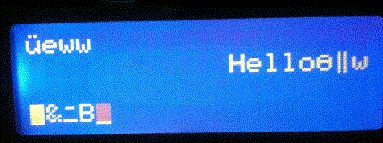
Zur Ausgabe benutze ich die erste Beispieldatei.

Weitere Änderungen habe ich am Code nicht vorgenommen, doch statt "Test
HELLO WORLD!" gibt das Display Zeichen aus die dem angehängten Bild zu
entnehmen sind.

Der Atmel ist zudem richtig gefused und die electrical connections i.o.


Weiss jemand Rat?
Bitte melde dich an um einen Beitrag zu schreiben. Anmeldung ist kostenlos und dauert nur eine Minute.
Bestehender Account
Schon ein Account bei Google/GoogleMail? Keine Anmeldung erforderlich!
Mit Google-Account einloggen
Mit Google-Account einloggen
Noch kein Account? Hier anmelden.