-
PDF
ControlPrint.pdf
1nF K 1nF K 1nF K +5V L L L GND D7 C GND D8 C GND C C4 ADC3 ADC1 C5 C6 C7 C8 C9 C10 C11 C12 C13 C14 C15 C17 D9 D10 100nF 100nF 100nF 100nF 100nF 100nF 100nF 100nF 100nF 100nF 100nF 220uF 4.7uF 7 LL4148 R4 7 LL4148 R5 4 C18 470k 4 C19 470k GND 1nF K 1nF K C C +5V GND GND P3 B 2 B 1 C22 +5V 4.7uF FAN_CON
in „LCD Display funktioniert nur wenn ich den uC Flashe“ · Mikrocontroller und Digitale Elektronik ·
-
PDF
Schematic_STM32L05__HSN-TTN_Mini_Node_LoRa_v1.2_2021-02-27.pdf
1 2 3 4 5 TP4056 Laderegler AKKU SOLAR HDR-M-2.54_1x2 HDR-M-2.54_1x2 4 5 1 VCC BAT 1 18650in HT7833 2 2 LDO LDO VCC-OUT 8 C13 2 3 A CE EP 9 10nF INA219 IN DOUT A U3 R2 LDO LDO G 0,1-RL1210FR-070R1L 7 CHRG# TEMP 1 1 A1 VIN+ 8 2 1 2 A0 VIN- 7 18650IN 1L▯ötbr▯ücke C10 C11 C8 3 SDA GND
-
PDF
drm001.pdf
Passive Infrared (PIR) Sensor Unit 27 Passive Infrared (PIR) Sensor Unit Compile/Link/Make: [PIR:cc.bat], [PIR:link08.bat], [PIR:make08.bat], [PIR:config.dat], and [PIR:jk.lkf] 2.6.1 On-Board MC68HC908JK1/MC68HC908JK3 20-Pin DIL Programmer The programming hardware is compatible with the ICS08JLZ software
in „AVR ATTiny84A mit C++ Werte an bestimmte Speicherstelle schreiben“ · Mikrocontroller und Digitale Elektronik ·
-
PDF
Akkuschutz-V0.6.pdf
i2C Adresse: 8 X1-3 ZELLE2 0x08 / 0000 1000 R12 1uF Gnd 10uF X7-2 NTC3 100R X1-2 ZELLE1 X7-3 NTC2 BAT 10 X1-5 VCC 12 VC5 X7-4 NTC1 13 VC4 REGSRC 9 GND R4 14 VC3 X1-1 MESSGND 1k F 15 VC2 REGOUT 8 4 0 16 VC1 I2C Display C 1 17 7 VC0 CAP1 Temperaturmessungen 6 ZELLE3 TS1 TS1 X2-4 +3V3 R5 F 18 5 C8 C9 C10
in „STM32WB5MMG -* ADC wackelt um 10 digits“ · Mikrocontroller und Digitale Elektronik ·
-
PDF
axpert_vm_iii5000__c.pdf
Possible reason 1. SPS module damaged. How to check 1. Firstly, please measure the resistor between BAT+ and BAT-. If it is not shorted, only connect the inverter with battery, and press “ON” button, could the inverter startup? If not, please check the fan. 2. If the LCD couldn’t light up and fan doesn
in „PV Wechselrichter startet nicht mehr und verursacht Kurzschluss bzw. hohen Strom“ · Analoge Elektronik und Schaltungstechnik ·
-
PDF
Schaltplan_DMS_Messverstaerker.pdf
EN NNR/FB R28 C26 10µF G 44.2kΩ 10nF F Q12 12 R35 C31 C20 F IN 10 150kΩ 100nF 4.7µF C28 C18 R39 4 BAT R29 5 Ilim1 LiPo 100nF 10µF 10kΩ 34.8kΩ 3 NTC C30 R51 2 CHRG 4.7µF G X4 G 1kΩ 1 CLPROG D PROG 8 + G R38 R44 C43 R34 R40 R42 5V_USB VCCIO 0Ω 10kΩ 100nF 2.2kΩ 1 3.3kΩ 1Ω Q20 NTC TPS73601 IN OUT H H Q14
in „Analog- und Digital-Teil bestmöglich trennen“ · Platinen ·
-
PDF
TransistorTester_eng_095k.pdf
probe resistor. 23. The Check of battery voltage is selectable in version 0.95k by the Makefile option BAT_CHECK. If selected, the output of the battery voltage is selectable too with option BAT_OUT. If the option BAT_CHECK is unselected, the software release number is displayed in row 1 of the LCD at the
-
PDF
Diagrams_TF-118_TF-100.pdf
R1 27 4.CKV K R0 TP23 C68 C69 C70 C71 26 G1 28 3.OEV L TP24 27 G0 R0 29 2.STVD B5 TP25 68 3K 82 150 15P 15P 15P 15P 15P 15P R5 28 R7 30 1.POL W B4 TP26 R4 29 R6 X B3 TP27 V4 C73 V11 C74 R3 30 R5 CON4 B2 TP28 0.1uF 0.1uF R2 31 R4 AT080TN03_1 Y B1 TP29 R1 32 R3 1 60.VCOM2 Z B0 TP30 R83 R84 R85 R86 R0 33
in „Photo-Rahmen als Farbdisplay“ · Mikrocontroller und Digitale Elektronik ·
-
PDF
Akku_Spannungswaechter.pdf
natürlich im Balken-Modus deutlich höhereufge- Akku-Gartenwerkzeugeusw. ImPrinzipistdieSchaltungauchalsBat-e, ohneBedeutung, bei 25VbeträgtdieVerlustleistungjedochschonca. terie-Testerverwendbar. AllerdingskönnennurBatteriengetestetwer- 625 mW, was für den LM3914 fast an der oberen Grenze liegt. Ohne den
in „Ladeelektronik Bleivliesakku“ · Analoge Elektronik und Schaltungstechnik ·
-
PDF
Schemativ_v1_1.pdf
IO26 11 IO26 IO17 28 IO17 IO27 12 IO27 IO16 27 IO16 +3V3 13 IO14 IO4 26 14 IO12 IO0 25 IO0 C5 D6 C10 15 24 330uF / 35V .SS34 330uF / 35V GND 16 GND IO2 23 17 IO13 IO15 22 R1 18 NC NC 21 10k▯' 19 NC NC 20 NC NC U1 GND GND GND GND ESP32-WROOM-32D(8MB) EN Power 3.3V Switch Buttons GND GND +3V3 +5V_EXT U4
in „ESP32 USB - C Schema“ · Mikrocontroller und Digitale Elektronik ·
-
PDF
si-prog-v2_2.pdf
PD1 PB6 (MISO) 17 3 D NB External power is needed only 6 TP CE 3 4 Xtal1 5 XTAL2 PB5 (MOSI) 16 4 D R15 NC VCC 5 XTAL1 PB4 5 J9 with some consuming device like 5 CLK D 4 6 6 PD2 (INT0) PB3 15 6 10K Select power ext/int non C-MOS devices (see 7 7 PD3 PB2 14 7 R11 JP2 SOCKET-DIP8 8 X1 8 PD4 (T0) PB1 (AIN1
in „Grundlagen: Teilen binär Teil 1 - Vorzeichenlose Ganzzahlen“ · Projekte & Code ·
-
PDF
eeprom_progger_schaltplan.pdf
PD1 PB6 (MISO) 17 3 D NB External power is needed only 6 TP CE 3 4 Xtal1 5 XTAL2 PB5 (MOSI) 16 4 D R15 NC VCC 5 XTAL1 PB4 5 J9 with some consuming device like 5 CLK D 4 6 6 PD2 (INT0) PB3 15 6 10K Select power ext/int non C-MOS devices (see 7 7 PD3 PB2 14 7 R11 JP2 SOCKET-DIP8 8 X1 8 PD4 (T0) PB1 (AIN1
in „Eeprom-Progger unter XP will keine 24Cxx bearbeiten“ · Mikrocontroller und Digitale Elektronik ·
-
PDF
AVRnDxBoard.pdf
/PA0 5V/3.3V Select C1 G N N N 3 A G G G JP3 Y1 5 7 1 7 15p 15p C9 100n 3 2 5 C8 User Leds +3.3V W2 PA1 R13 D2 J3 W1 1 PA0 2 1K DNP 3 R14 D3 4 1K Conn_01x04 R15 D4 1K R16 D5 1K D D Potentiometer VCC J4 1 1 5V 2 RV3 2 H Potentiometer supply 10K VREF 3 VREF voltage
-
PDF
ttester.pdf
Versionen an den Batterie Wechsel zu erinnern. Beispiel: CFLAGS += -DBAT_CHECK BAT_OUT schaltet die Batterie-Spannungsanzeige auf dem LCD ein, wenn BAT_CHECK ge- wählt wurde. Wenn Ihre 9V-Versorgung eine Diode wegen des Verpolungs-Schutzes installiert hat, können Sie die Form BAT_OUT
in „Sammelbestellung Transistortester III - schnelle Runde“ · Markt ·
-
PDF
ttester_ger109k.pdf
Versionen an den Batterie Wechsel zu erinnern. Beispiel: CFLAGS += -DBAT_CHECK BAT_OUT schaltet die Batterie-Spannungsanzeige auf dem LCD ein, wenn BAT_CHECK ge- wählt wurde. Wenn Ihre 9V-Versorgung eine Diode wegen des Verpolungs-Schutzes installiert hat, können Sie die Form BAT_OUT
in „Sammelbestellung Transistortester III - schnelle Runde“ · Markt ·
-
PDF
MCP79521.pdf
. UNLOCK Instruction CS with 0x55 Data Byte 0 1 2 3 4 5 6 7 8 9 10 11 12 13 14 15 SCK Instruction Data Byte SI 0 0 0 1 0 1 0 0 0 1 0 1 0 1 0 1 2. UNLOCK Instruction CS with 0xAA Data Byte 0 1 2 3 4 5 6 7 8 9 10 11 12 13 14 15 SCK Instruction Data Byte 0 0 0 1 0 1 0 0 1 0 1 0 1 0 1
in „RTC -> MCP79521“ · Mikrocontroller und Digitale Elektronik ·
-
PDF
Siemens_B1023_Norma_MP14.pdf
Batteriezustandskontrolle: Bei Absinken der Batteriekapazität auf typ.lO % ihres Sollwertes erscheint "LO BAT" am Display. Meßbereichswah1 : automatisch und manuell Zentralschalter (11 Stellungen) für Funktions- und Bereichswahl, getrennter EIN/AUS-Schalter. Umschaltzeit für automatische Bereichswahl: 0,15
-
PDF
b_1023.pdf
Batteriezustandskontrolle: Bei Absinken der Batteriekapazität auf typ.lO % ihres Sollwertes erscheint "LO BAT" am Display. Meßbereichswah1 : automatisch und manuell Zentralschalter (11 Stellungen) für Funktions- und Bereichswahl, getrennter EIN/AUS-Schalter. Umschaltzeit für automatische Bereichswahl: 0,15
in „Hilfe bei Reparatur Siemens Multimeter“ · Analoge Elektronik und Schaltungstechnik ·
-
PDF
SCHEMATIC1___PAGE1.pdf
5 4 3 2 1 U3 D2 MBR0540T1 U4 D L1 VCC VDD D J2 5 VIN BOOST 1 C10 15uH 1 IN OUT 3 2 D 1 10k 4 EN SW 6 10nF R5 G C1 R4 4.7uF 2 3 LM39402TO220 CON2 GND FB C11 30.1k 20nF LM2736xmk R6 10k 0 D3 C2 BAT54-7-F 4.7uF 0 22.1184MHz Y1 C6 C7 0 C U1 33pF 33pF C 26 27 XTAL1 XTAL2
in „C8051F020 P1 als Ein- und Ausgang“ · Mikrocontroller und Digitale Elektronik ·
-
PDF
ST__L200.pdf
Figure 13. Ou tput Impedance vs. Figure 14. Output Impedance vs. Output Frequency. Current. Figure15. VoltageTransientReponse. Figure 16. LoadTransientReponse. 6/12 L200 Figure17.Load Transient Reponse Figure 18. Current Limit Sense Voltage vs. JunctionTemperature. APPLICATIONS CIRCUITS Figure19. -
in „liegender einstellbarer Spannungsregler“ · Analoge Elektronik und Schaltungstechnik ·
-
PDF
lpc2468board.pdf
3 4 5 6 7 8 1 2 3 4 5 6 7 8 VCC A A X5 1 BOOT 2 R59 4k7 CON2 VCC VCC R60 R61 V13 56 56 BC846B V14 V15 V16 BAT54 KP-2012YC KP-2012YC R62 R63 4k7 4k7 GND GND V17 V18 R64 BC846B BC846B 4k7 X6 GND GND 1 2 3 B B 4 5 D10 6 TXD0 11 T1IN T1OUT 14 7 10 7 8 12 T2IN T2OUT 13 9 RXD0 R1OUT R1IN 9 R2OUT R2IN 8 DTS09PYCSMD2UN GND C61 1 C1+ C2+ 4 C62 100n 3 5 100n C1- C2- 16 6 VCC V- C63 2 15 100n VCC V+ GND C64 ADM3202ARN 100n GND GND C65 VCC 100n C C GND R65 4k7 X7 1 V19 2 BC846B RESET CON2 V20 BAT54 GND GND D D * Not assembled components Created: 01.10.2009 TPL ARM7-Controllerboard Checked
in „NXP verschenkt ARM-Chips“ · Mikrocontroller und Digitale Elektronik ·
-
PDF
swBalancer.pdf
PC6(/RESET) PC0(ADC0) 3 100n PC1(ADC1) 24 V 470k 21 25 + R39 U3 R20 33 33 Quarz JLCPCB Partnumber C15 GND PC2(ADC2) IC4 330 33 R61R19 Q13FC1350000400 20 AREF PC3(ADC3) 26 1 4 10018 27 R40 14 15 C3 + C16 AVCC PC4(ADC4/SDA) 28 270k SER QA 1 R22 2 3 PC5(ADC5/SCL) 10k 10k 10k QB R11 +3V3 100n ADC6 19 11
in „SuperCap Balancer mittels µC“ · Analoge Elektronik und Schaltungstechnik ·
-
PDF
ttester.pdf
GND) 2 1 3 1 VO (Drive) 3 3 (5) 3 DB0-DB3 4-7 7-10 9-12 7-10 DB4-DB7 8-11 11-14 13-16 11-14 CS1 12 15 1 15 CS2 13 16 2 16 Reset 14 17 - 17 R/W 15 5 7 5 RS 16 4 6 4 E 17 6 8 6 VEE 18 18 - 18 LEDA 19 19 17 (19) LEDK 20 20 18 - Tabelle 2.5. Pinbelegung verschiedener NT7108 Module Die Tabelle 2.6 zeigt die
-
 Bild
Handgezeichnete Skizze einer elektrischen Schaltung
Bat 4,5V 0,5V 15V
in „Was ist dieses Bauteil (ca. 1972)“ · Analoge Elektronik und Schaltungstechnik · · Diagramme

-
PDF
EMS_PIC.pdf
E 3 4 2 4700µH V DC1 1 D7 7 6 + 2 4 1µ2H L1 C1 D EMS_TX 2 0 4 R 100n +VIN +VOUT 100n 100n 3 D JP1 BAT54S S C 1 3 IC1A 1 3 L3 V A 68p 4 R1 3 n 1 R7 C6 -VIN -VOUT C7 C8 U1P A 4700µH D8 5 A 10K C 1 2 4k7 EMS_232_RX DC/DC CONVERTER L2 D B R 2 LM393D VA-0505S 2 S 9 R K 3 4 5 V DBAT54S 3 4 1 0 R N D 1 SJ2
in „Buderus EMS-"Gateway" mit PIC18F / Sammelbestellung“ · Haus & Smart Home ·
-
PDF
uC-Board.pdf
IN1 1 1 9 C 2 1 I I C 2 I C 2 +5V 1 2 P P MOSFET-Switches I P I I I BQ255 P 6 5 4 3 2 1 P Connector_Bat P P P P P P $ $ C C $ P P u 2 15 2 2 U D 12 2 VIN_DC VSTOR I I + I - N D T N 1 A2 A VRDIV 7 P P IRF 7410 C V C D N O G I P P 14 VBAT S G V P 8 VBAT_UV VBAT_OK 11 S1 S1 D1 D1 # 16 S2 D2 $ $ 3 LBST S3
in „AtMega1284P+XBee funktioniert nicht ohne ISP“ · Mikrocontroller und Digitale Elektronik ·
-
PDF
Athlet_BCH6L2560_SCH.pdf
(PCINT0/CLKO/ICP1)_PB0 GND 21 T G O R103 13 20 GND TP36 1 2 14 (PCINT1/OC1A)_PB1 AREF 19 1K 3 D D 15 (PCINT2/SS/OC1B)_PB2 ADC6 18 1 C L L (PCINT3/OC2A/MOSI)_PB3 AVCC C13 C 16 (PCINT4/MISO)_PB4 PB5_(SCK/PCINT5) 17 7 7 7 7 2 R 2 R TP38 C12 GND GND GND GND TP41 2 0 R 1 TP39 TP26 TP34 3 4 5 TH1 2 E E E
in „Bosch Athlet 25,2 V Akku 7 Stück Tauschen“ · Analoge Elektronik und Schaltungstechnik ·
-
PDF
2013-07-31_UT61A-E.pdf
.................................................................................................. 15 6.8 Automatische Abschaltung, Auto-Power-Off..............................................................................15 7. Batteriewechsel.............................................................................................................15.................... 8. Sicherungswechsel.............................................................................................................................16 9. Wartung, Lagerung und Pflege
in „Messungen mit DMM Dual-Slope Verfahren am PMOS“ · Analoge Elektronik und Schaltungstechnik ·
-
PDF
MPLINK_TUTORIAL.pdf
thes® in your AUTOEXEC.BAT file and check them by going to the MS-DOS prompt and typing SET. MPLINK sets the library path to C:\MCC\LIB. If MPLAB-C17 is installed somewhere else, change the path in the MPLINK line of the batch
in „Anfängerfrage zu Assembler“ · Mikrocontroller und Digitale Elektronik ·
-
 Bild
KingSpec M.2 NVMe SSD auf Laptop-Mainboard
KingSpec M.2 NVMe SSD NE 2242 Mitsubishi CR2032 2018.10.15 BAT2 RTC
in „NVMe m.2 B+M Key SSD Verlängerung“ · PC Hard- und Software · · Platinenfotos

-
PDF
SL2470C_SL2450C_Bedienungsanleitung.pdf
Minuspol). leiteranschluss nach Nur bei SL 2470 C: VDE 0551 e/75; BeiFalschpolungwirdLadungverhindert, CEE15 rote Kontrolleuchte (2) leuchtet dann auf. Ladestrom „Normalladung“ SL2450C 6. Ladung, Starthilfe 6 V max. 15 A (arithm.) 22 A (effekt.) 12 V max. 15 A (arithm.) 22 A (effekt.) 1 Spannungs- und Ladestromwahlschalter
in „Trafo Draht 1,28mm durch 1,32mm ersetzbar?“ · HF, Funk und Felder ·
-
Datei
main.c
volatile uint8_t ADC_i; volatile uint8_t messintervall = 128; // Messintervall für analoge Messung: 15,625ms * 128 = 2sek // 16 Bit uint16_t Spannung_FZ, Spannung_Bat; uint16_t x_max=0, x_min=0xffff, y_max=0, y_min=0xffff, z_max=0, z_min=0xffff; // Variablen für maximalen bzw. minimalen Wert // 8 Bit
in „AD-Wandlung und Nutzung JTAG möglich?“ · Mikrocontroller und Digitale Elektronik ·
-
PDF
DW03D_________IC_.pdf
DW03D (文件编号:S&CIC0953) 二合一锂电池保护 IC 六、 极限参数 参数 符号 参数范围 单位 电源电压 VDD VSS-0.3~VSS+12 V OC 输出管脚电压 VOC VDD-15~VDD+0.3 V OD 输出管脚电压 VOD VSS-0.3~VDD+0.3 V CSI 输入管脚电压 VCSI VDD+15~VDD+0.3 V 工作温度 Topr -40~+85 ℃ 存储温度 Tstg -40~+125 ℃ 七、 电气特性参数 参数 符号 测试条件 最小值 典型值 最大值 单位 工作电压 工作电压 VDD -- 1.5 -- 10 V 电流消耗 工作电流 IDD VDD=3.9V -- 4.0 6.0 uA 检测电压 过充电检测电压 VOCD -- 4.25 4.30 4.35 V 过充电释放电压 VOCR -- 4.05 4.10 4.15 V 过放电检测电压 VODL -- 2.30 2.40 2.50 V 过放电释放电压 VODR -- 2.90 3.00 3.10 V 过电流 1 检测电压 VOI1 -- 0.12 0.15 0.18 V 过电流 2(短路电流)检测电压 VOI2 VDD=3.6V 0.80 1.00 1.20 V 过电流复位电阻 Rshort VDD=3.6V 50 100 150 KΩ 过电器检测电压 VCH
-
 Bild
Elektronik-Messaufbau mit Display und Breadboard
1-3 [RL] 48.7Ω L=10.0mH Bat. 8.4V OK 35 40 50 55 60 25 20 15 5 0
in „Induktiver Positionssensor - Fragen dazu“ · Mikrocontroller und Digitale Elektronik · · Fotos

-
Datei
firefly2.h
include "wave.h" /* PB0 = = InOut = LED1 PB1 = = InOut = LED2 PB2 = = InOut = LED3 PB3 = ADC3 = Input = Bat+/Solar+ PB4 = ADC2 = Input = Solar- PB5 = = InOut = LED4 PB6 = = InOut = LED5 PB7 = = InOut = LED6 PD0 = = InOut = LED7 PD1 = = InOut = LED8 PD2 = = InOut = LED9 PD3 = = InOut = LED10 PD4 = = InOut
in „Glühwürmchen in Rotkohlglas gefangen“ · Projekte & Code ·
-
Datei
main.c
volatile uint8_t ADC_i; volatile uint8_t messintervall = 128; // Messintervall für analoge Messung: 15,625ms * 128 = 2sek // 16 Bit uint16_t Spannung_FZ, Spannung_Bat; uint16_t x_max=0, x_min=0xffff, y_max=0, y_min=0xffff, z_max=0, z_min=0xffff; // Variablen für maximalen bzw. minimalen Wert // 8 Bit
in „AD-Wandlung und Nutzung JTAG möglich?“ · Mikrocontroller und Digitale Elektronik ·
-
PDF
l200.pdf
o V B = 1 MHz 80 Vo Output Voltage Range Io= 10 mA 2.85 36 V V o Voltage Load Regulation o = 2 A 0.15 1 % V (note 1) o= 1.5 A 0.1 0.9 % o Vi Line Regulation V 0 5 V V V i 8 to 18 V 48 60 dB o SVR Supply Voltage Rejection V 0 5 V o = 500 mA Vi= 10 Vpp f = 100 Hz (note 2) 48 60 dB Vi-o Droupout Voltage
in „L200 Beschaltung“ · Analoge Elektronik und Schaltungstechnik ·
-
PDF
Schematic.pdf
VBAT GND D D SH5 10 C0805 C0402 6 VDD RST 9 VBAT 3 2 LED0603 G G SH6 11 SUSPEND_HIGH 17 SOT-23 C 2 15 G C 3 2 MICRO_USB_SMT GND SUSPEND_LOW CJ2301/NC 1 V BAT VCC D15 1N4148 8 1 CHRG 5 VBUS SOD323 VBUS RI 24 1 D5 BS5819 SL C21 PROG PH-2-WO D DM 4 DCD 23 DTR VBUS SOD-123 N D D- DTR 100nF G DSR 22 C0402
in „Stromverbrauch ESP32 Devboard TTGO T8 minimieren“ · Mikrocontroller und Digitale Elektronik ·
-
 Bild
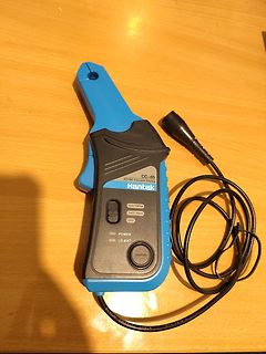
Hantek CC-65 AC/DC Stromzange
CC-65 AC/DC Current Clamp Hantek 1mV/100A 1mV/15A OFF POWER LO BAT Hantek ELSUN COAXIAL CABLE SYV-75-2-2
in „[V] Stromzange Hantek CC-65 defekt“ · Markt · · Fotos
-
 Bild
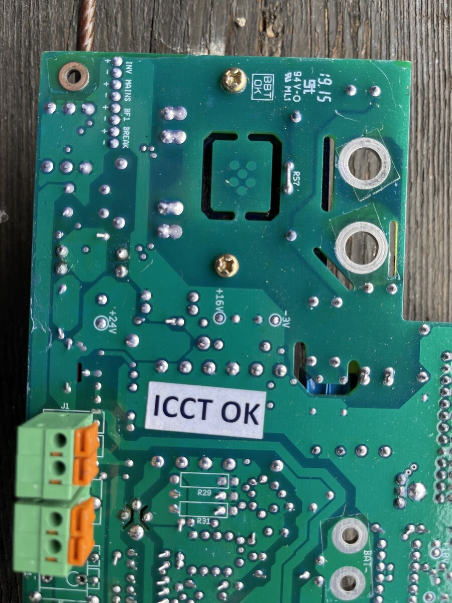
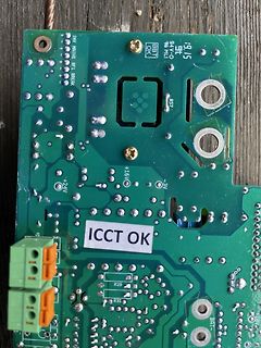
Nahaufnahme einer grünen Leiterplatte
INV MAINS BF1 BREAK, 94V-O, MLI, ST, .9.15, BBT, OK, R57, +16V, -3V, +24V, ICCT OK, R29, R31, BAT+
in „Victron 48/8000 Quattro zeigt im ESS zu niedere Spannung an?“ · Analoge Elektronik und Schaltungstechnik · · Platinenfotos
-
 Bild
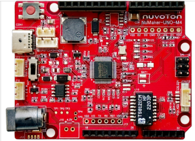
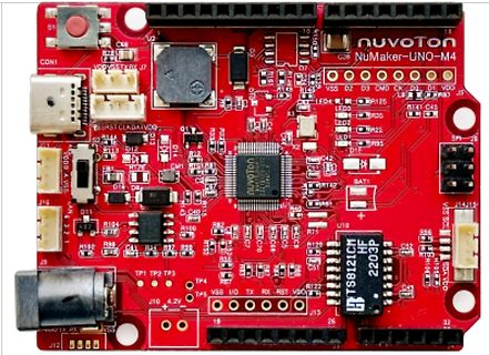
NuMaker-UNO-M4 Mikrocontroller Board
NuMaker-UNO-M4 Nuvoton TS8121CH 2203P BAT1 J14 J15 J16 J12 J10 4.2V TP1 TP2 TP3
in „FPGA-Boards, Nuvoton-Arduino und preiswertes LoRA-Funkmodul“ · Mikrocontroller und Digitale Elektronik · · Platinenfotos
-
PDF
LTC6803-2_4.pdf
S8 11 34 WDTB C7 12 33 NC C7 12 33 TOS S7 13 32 TOS S7 13 32 VREG C6 14 31 V C6 14 31 V REG REF S6 15 30 VREF S6 15 30 VTEMP2 C5 16 29 VTEMP2 C5 16 29 VTEMP1 S5 17 28 V S5 17 28 NC TEMP1 C4 18 27 NC C4 18 27 V– – S4 19 26 V S4 19 26 C0 C3 20 25 S1 C3 20 25 S1 S3 21 24 C1 S3 21 24 C1 C2 22 23 S2 C2 22
in „uC für Schaltregler“ · Mikrocontroller und Digitale Elektronik ·
-
 Bild
Schaltplan einer LED-Schaltung mit Transistoren
R2 100K R3 470 C1 100µ R1 15K D1 LED Rv1 470 C3 10µ T1 NPN T2 NPN Bat. 9V
in „Oszillator welche Schaltung / Blinkschaltung“ · Analoge Elektronik und Schaltungstechnik · · Schaltpläne

-
PDF
MC33290-single-wire.pdf
40 to 125°C SO-8 8.0 kV ESD Protection Attainable with Few Additional Components Standby Mode: No V BatCurrent Drain with VDD at 5.0 V Low Current Drain During Operation with V DD at 5.0 V 33290 Simplified Application Diagram On-Board Diagnostic Link +V Bat Service Scan Tool 45 V(2) or End of Production
in „RX und TX auf einer Leitung“ · Mikrocontroller und Digitale Elektronik ·
-
PDF
BluePillPlus_V10_SchDoc.pdf
PIU1026 PB13 PA11PIP208 8 PB0IP108 8 1 PA14PI U1037 PIU1027 PB14 PA12PIP209 9 PA7PIP109 9 10pFP0 PA15 38 PA14/JTCK/SWCLK PB14/SPI2_MISO/USART3_RTS/TIM1_CH2N 28 PB15 PA15PI2010 10 PA6PIP100 10 2 PI U1038 PA15/JTDI/TIM2_CH1_ETR/SPI1_NSS PB15/SPI2_MOSI/TIM1_CH3N PIU1028 C4 PI2011 PA5IP101 11 GND PIX102
in „BluePill STM32 Bezugsquelle“ · Mikrocontroller und Digitale Elektronik ·
-
 Bild
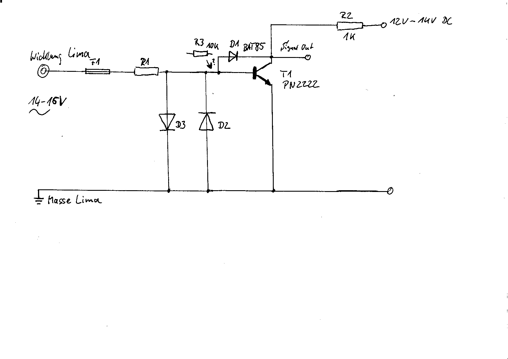
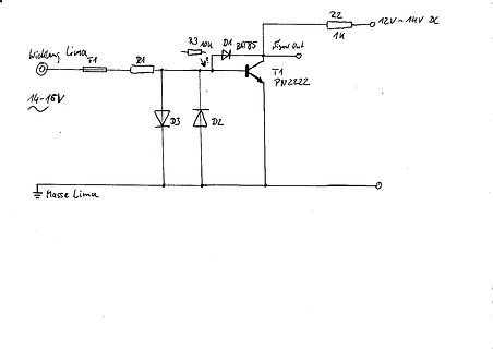
Handgezeichneter Schaltplan einer Schaltung mit Transistor
Wicklung Lima, 14-15V, R1, F1, R3 10K, D1 BAT85, T1 PN2222, Signal Out, R2 1K, 12V~14V DC, D3, D2, Masse Lima
in „Signalaufbereitung aus der Wicklung einer Drehstromlima“ · Fahrzeugelektronik · · Schaltpläne
-
 Bild
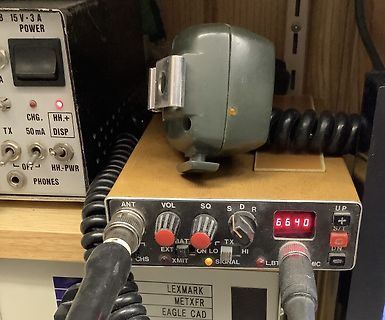
Funkgerät und Netzteil in einer Werkstatt
15 V 3 A POWER CHG. HH.+ TX 50 mA DISP OFF HH.-PWR PHONES ANT VOL SQ S D R 6640 UP BAT EXT TX S/T ON LO HI DN CHS XMIT SIGNAL L.BT MIC LEXMARK METXFR EAGLE CAD
in „Zeigt her Eure interessanten historischen Bauelemente“ · Offtopic · · Fotos
-
 Bild
Elektronik-Messaufbau mit Multimeter und Platine
DE-960TR, DCV A, ACV, RFE, BAT, OD-ADJ, 1000, 250, 50, 10k, 1k, x1, x10, hFE, COM, DCmA, 2.5, 250, 2.5A, 10, 9, 8, 7, 6, 5, 4, 3, 2, 15
in „Darlington Transistoren mit internen Widerständen“ · Analoge Elektronik und Schaltungstechnik · · Fotos

-
PDF
L200.pdf
Figure 13. Ou tput Impedance vs. Figure 14. Output Impedance vs. Output Frequency. Current. Figure15. VoltageTransientReponse. Figure 16. LoadTransientReponse. 6/12 L200 Figure17.Load Transient Reponse Figure 18. Current Limit Sense Voltage vs. JunctionTemperature. APPLICATIONS CIRCUITS Figure19. -
in „L200 Beschaltung“ · Analoge Elektronik und Schaltungstechnik ·
-
PDF
HP_MSA-0520.pdf
• High Output Power: MMIC is designed for use as a general purpose 50 gain block. +23dBmTypicalP 1dBat Typical applications include 1.0GHz narrow and broad band IF and RF • LowDistortion: amplifiers in industrial and 33dBmTypicalIP at130 GHz military applications. • 8.5 dB Typical Gain at 1.0 GHz The
in „[S] RF-Transistor AT-64020 oder einen adäquaten Ersatz“ · Markt ·