DES COMPOSANTS 6. Mesurer la température finale de l’eau. (Exemple: La température finale est T2 = 21°C) 7. Calculer la puissance de sortie des micro-ondes P en Watts à l’aide de la formule ci-dessus. Températureinitiale ................................................................................
personenbezogener Daten entspräche dem Erfordernis einer Kopie nicht (EuGH C-487/21, Österreichische Datenschutzbehörde und CRIF, Rn 21; C-579/21, Pankki, Rn 64). [9] Die Kopie muss eine originalgetreue und verständliche Reproduktion aller personenbezogenen Daten enthalten
Person die wirksame Ausübung der ihr durch die DSGVO verliehenen Rechte zu ermöglichen (EuGH C-487/21, Österreichische Datenschutzbehörde und CRIF, Rn 41, 45; C-579/21, Pankki, Rn 64 ff; C-307/22, FT gegen DW, Rn 74 f; vgl Bäcker in Kühling/Buchner, Datenschutz- Grundverordnung/BDSG4 [2024] Art 15 DS-GVO
W R _ F P L n G G G G G O G G G P K e G D D D D D U D D D N N e D T t GND 29 28 27 26 25 24 23 22 21 20 19 18 17 16 15 GND GND 30 14 GND SWCLK GND 31 13 GND 32 12 SWDIO GND 33 11 Host_IRQ_BLE GND 34 10 Host_IRQ_WL GND 35 9 Logger GND 36 65 62 59 8 SDIO_D0 3V3_IN 37 7 SDIO_D1 64 61 58 3V3_IN 38 6 SDIO_D2
''' Realtime Speech Recognition with "Ende" recognition 21.4.2026 mchris HOWTO: 1. Change the python environment e.g. source ~/tools/venv/ch/bin/activate 2. run the script python whisperVAD.py INSTALLATION: Difficulties - you have to find out the device_id of
due to achievable latencies on FPGAs continuing to lag behind mod- . Full pipelining: this is the base requirement for the hardware implementation to achieve high performance; ern microprocessors with higher clock frequencies, floating- . Ease of use: the standard interface appears as a normal point accelerators
ANODE Magnetic characteristics of photomultiplier tubes for highly magnetic fields (1) INPUT WINDOW 21-PIN BASE HA TREATMENT PHOTOCATHODE THBV4_1309EA Figure 13-9: Structure of a photomultiplier tube designed for use in highly magnetic fields 10 2 TETRODE TYPE N A 1 G 10 TRIODE TYPE THBV4_1309EA 10 0
CIRCUIT Figure 20. Turning Off the Converter by Sinking Figure 21. Fault Memorization the Base Current to Ground Q1 C Lp p Q2 TUBE +V CC R1 D1 Q3 R3 R2 C1 DIAGNOSTIC CIRCUIT Figure 22. Using the Emitter Switch Off Technique to Stop the Converter Power Factor Correction
Ein sicher unkonventioneller Vorschlag: Analogkamera und LCD-Display mit (F)BAS Eingang. Das Signal vorher invertieren und den Kontrast hochdrehen. Benötigt drei Transistoren. Dann die einzelnen Segmente mit Fotodioden/Fototransistoren vom Display ablesen.
mit 9600Baud 8-N-1, was recht einfach auszulesen wäre. Die Daten kommen demnach nach DIN EN 62056‐21 (2.5.3) raus. Die Norm scheint mir nicht grad übersichtlich, aber es vermutlich schaff ich es den Datensalat auszuwerten, muss ja nur decodieren nicht Kommunizieren. Somit brauch ich einen Empfänger
Speed Serial Peripheral Interface(SPI MODE 0, 3) - Internal 32Kbytes Memory for TX/RX Buffers - 10BaseT/100BaseTX Ethernet PHY embedded - Supports Auto Negotiation (Full and half duplex, 10 and 100-based ) - Not supports IP Fragmentation - 3.3V operation with 5V I/O signal tolerance - LED outputs (Full
Properties: Turns Ratio n 1 : 1 ±2% Plastic Housing Material Thermoplastic PA66 Black Data rate 100BASE-TX Plastic Housing Flammability Rating UL94 V-0 LED Electrical & Optical Properties: Shielding Material Brass Value Properties Test conditions min. max. Unit Shielding Plating 50µ" Nickel Forward Voltage
Hallo zusammen, ich versuche zur Zeit eine Ora (Companion) P21 - wurde unter anderem Namen unter der Bezeichnung "Ingrid Orgel Student 49" vertrieben - zu reparieren. Ich bin nun an dem Punkt angelangt wo ich ohne Schaltplan nicht weiterkomme und suche auf diesem
der Mitte der Platine. Der Klassiker mit Schleifer auf der Basis des Transistors der zwischen den Basen der Endstufen liegt.
wireless connection ensures that the mobile unit consistently receives the necessary RTCM data from the base station, maintaining high-precision positioning even at a distance. [/c] ### Microchip PIC32CM * PL10 – mit AVR Dx kompatibler 32-Bitter Microchip möchte Nutzern der AVR Dx-Familie einen Weg zum
Antenne, die für die Videoübertragung im Bereich von 5-5.9GHz optimiert ist. 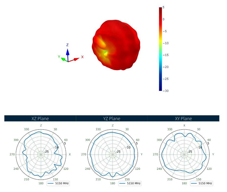 Bildquelle: Taoglas ### OSRAM SFH 7019 – Grün, Infrarot und UV-A in einer LED RGB-Dioden, die verschiedene Arten von sichtbarem Licht kombinieren, sind per Se nichts neues. OSRAM lanciert
ACTUATION ..........................................................................................21 7.3 C HECKING THE INDIVIDUAL COMPONENTS ............................................................................................................21 7.4 C ONTROL VOLTAGE ...........................
Schutz abgekündigt: ähnliche Funktionen, gleicher Hersteller: TJA1053, TJA1054 UJA1061. NXP System Base Chip (SBC) TSSOP 32-Pin Serial Interface (SPI) Spannungsregler 3.3 V oder 5.0 V (LDO) 6kV ESD Schutz L4969. ST Microelectronics System Base Chip (SBC) SO20 Serial Interface (SPI) Spannungsregler (LDO) MC33889. Motorola Freescale System Base Chip (SBC) SO28 Serial Interface (SPI) Spannungsregler (LDO) CAN Repeater. AMIS-42700. Dual High-Speed CAN Transceiver High speed (up to 1Mbit/s) SOIC-20 vgl. Alternative. zwei Transceiver Schaltung
www.qualcomm.com/internet-of-things/products/q2-series/qrb2210 Der Ventuno Q – der Name steht übrigens für 21 – startet nun eine leistungsstärkere Platine, die auf dem IQ-8275 basiert und somit wesentlich mehr Rechenleistung bietet. 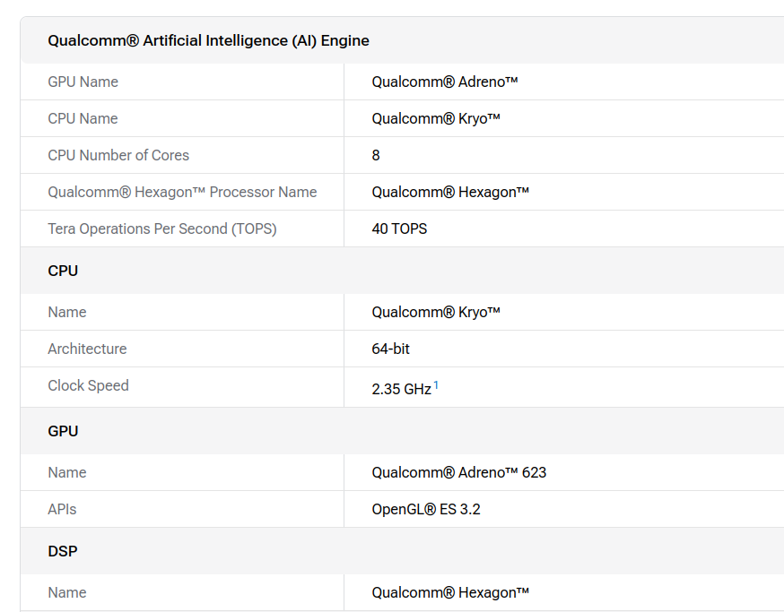 Bildquelle: https://www.qualcomm.com/internet-of-things
i_got_frustrated_by_the_lack_of_an_official/ die folgende Passage: [c] I didn't want this to just be a modified Debian base. I wanted it to be as close to official as possible. The pipeline uses a GitHub Action that downloads the official Raspberry Pi OS Lite .img.xz releases directly from downloads.raspberrypi.com. It
draft. 12/08/08 Check the grammar and syntax, Update the data ,the key features, and user control 0.21 registers, Delete the Section 4.6 Audio Encryption for Privacy , Modify the Vcc 02/23/09 value ;modify the pin FMO back RFO; 0.22 Modify Table 6: match the notes with the parameters; add “at maximal
regulator capable of delivering 10 mA to external circuitry. Osc 17 Oscillator input. A transistor base preseto an external subcarrier input, or is available for in constructing a Colpitts oscillator (see Figure 4). Oscout 18 Oscillator output. The emitter of the transistor, with base access at Pin 17
www.swissbit.com/contact Page 2 of 21 U-500 Series – Industrial USB Flash Drive Module (eUSB) 1GB up to 32GByte (SLC) 1. Product Summary • USB3.1 solid state flash drive for internal 9(10)-pin USB connector terminal o Fully compliant with
getrennt zugeführt. Zur Ansteuerung eines Monitors mit kombiniertem Video- und Synchronisationssignal (BAS-Eingang) müssen die drei Ausgänge BAS, /HSYN und /VSYN zur Erzeugung des BAS-Signals miteinander verbunden werden. Sie sind dazu mit Open-Kollektor-Treibern versehen. Die Pegel können gegebenenfalls
MO-161 Pin 1 n v t 1.27 . (Top view dimensions are the [.050] w same for all variations.) Typ. w 0 Base Part Numbers A 3.68 B 2 390074 [.145] 21.39 - 390168 2 Plc. [.842] 5 Typ. 2 0 See table below showing complete 60.96 8 part numbers. A [2.400] B 13.07 : 121.92 Ref. [.514] a [4.800] Typ. r Ref. l c
bei VW/MFSW eine empfohlene Master-Beschaltung (R + Diode) bzw. > Terminierung, die du kennst? BAS21 + 2x 2 kOhm 1206 parallel gegen KL30, 1 nF gegen Masse. Dann einen nicht bestückten 0805er Ferrit mit 0 Ohm parallel, dann eine nicht bestückte PESD1LIN gegen Masse. Je nachdem was Du damit vorhast
00000028 T HAL_SYSTICK_Config 08000387 00000008 T HAL_SYSTICK_IRQHandler 08001b35 00000060 T HAL_TIM_Base_Init 08003225 0000004e T HAL_TIM_Base_MspInit 08001b99 00000002 W HAL_TIMEx_Break2Callback 08001b97 00000002 W HAL_TIMEx_BreakCallback 08001b95 00000002 W HAL_TIMEx_CommutCallback 08001e83 00000004
Mes ung betätigen. DiieMeessung ebeginnt nach Auftret nendes externenn Trriggerfreigabe-Impulses. 2-21 2-21 Bedienung de Univers llzählers Die Me nütaste G te & Ex tArm Verfahrr nz ur Ä derungng d er Anz eigestellen für die Au löung g zu Erz ei lung ge nauererr Mes sungen(Be s i piel) 1 D ie T ste POWER
laufen der mir die Statistiken ausliest / speichert. Als Code-Completion habe ich qwen2.5-coder:1.5b-base - sehr schnell und macht was es soll: [code] name: Local Config version: 1.0.0 schema: v1 models: - name: qwen3.5:9b provider: ollama model: qwen3.5:9b apiBase: http://192.168.231.21
option modules - Standalone Applications contain a high-performance microprocessor that allows the base drive to be dedicated to motion control as well as • Motion Control Functionality machine control. - Velocity, Torque Mode - Position-Indexing - Synchronization, Electronic Gearing SM-EZMOTION - CAMS
20k-Poti verwenden - gibt es, ist aber eher unüblich. Die 4 Spannungsquellen in Reihe zu den Basen sind nur zu testzwecken (flat(2m) bedeutet, dass bei jedem Simulationslauf die Spannung zufällig gleichverteilt zwischen -2mV und +2mV festgelegt wird) um nachzuvollziehen, wie groß die Abweichungen
also wo der Vorteil gegenüber einem logarithmischen Poti direkt am 555 ist. Piher nennt für sein T-21 Potis unter 100k einen Temperaturkoeffizienten von +-300ppm/K. Dazu einen PP Folienkondensator am 555, fertig. Damit bleibt man unter 0,05%/K Temperaturgang.
TJ, JUNCTION TEMPERATURE (°C) VI, INPUT VOLTAGE (V) Figure 20. Output Voltage vs. Junction Figure 21. Current Consumption vs. Input Temperature, Adjustable Version Voltage, Adjustable Version 4 2 ) 3.5 T J 25°C 0 ( R L 20 W A E m −2 G 3 T T N −4 L 2.5 E −6 V R T 2 U −8 P C T U−10 U 1.5 P , ,−12 VQ 1
is supported by the link partner 0 = 10BASE-T half duplex is not supported by the link partner 4:0 Selector RO Protocol Selection Bits 0h Link partner’s binary encoded protocol selector Preliminarydatasheet 21 DM8603-12-DS-P01 November8,2010
Classification Disable The priority information from VLAN tag field is ignored. 1:0 P_PRI PE0,RW Port Base priority The priority queue number in port base. 00= queue 0, 01=queue 1, 10=queue 2, 11=queue 3 6.21 Per Port VLAN Tag Low Byte Register (6EH) Bit Name Default Description 7:0 VID70 PE01,RW VID[7:0

 Bild
Bild

 Bild
Bild
 Bild
Bild