aus der nachstehenden For details please refer to the following checklist: Bandbreite: min. 10 mm max. 400 mm Strip width: min. 10 mm max. 400 mm Checkliste: Streifenlänge: min. 20 mm max. 3000 mm Strip length: min. 20 mm max. 3000 mm Lochdurchmesser min. 4,5 max. 28 mm Hole diameter: min. 4.5 mm max. 28 mm Bandbreite: min. 10 mm max. 400 mm Strip width: min. 10 mm max. 400 mm AnzahStreifenlänge: enen Lmin. 20 mm ser: max. 3000 mmmax. 3 NumbStrip length: t diamemin. 20 mm max. 3000 mm max. 3 Materialstärke 0,27 / 0,30 / 0,35 / 0,50
and V ds being the intrinsic drain-source voltage. The charge and capacitances are: for V > V new max 168 V max Vnew − V max Q gs = Cgs0· 2·Vbi 1 − 1 − + (11.364) V bi 1 − VVax bi ∂Q gs C gs0 ∂Vnew = · (11.365) ∂Vgs 1 − VVax ∂V gs bi ∂Q gs C gs0 ∂Vnew = · (11.366) ∂Vgd 1 − VVax ∂V gd bi and
asiatischen Händlern erhalten kann. Elektor definierte folgende Mindestanforderungen an TUN: U CEO / V I C max. / A h FE ( ) P max. / W f T / MHz 20 0,1 100 0,1 100 Das sind keine hohen Anforderungen. Gehäuseform und Anschlussbelegung wurden nicht definiert. Als Beispiele für TUN gab Elektor folgende Typen an
ULN2801 ULN2802 ULN2803 ULN2804 DIL18 SO18 50 0,35 1 kHz 8x Low-Side NPN-Darlington, Freilaufdiode, max 500mA insgesamt Rei, Far, alle alldatasheet.com 0,35 - 0,50 UDN2981 DIL18 SO18 50 0,35 1 kHz 8x High-Side NPN-Darlington, Freilaufdiode, max 500mA insgesamt, obsolete, Ersatz: Micrel MIC2981 Rei, Far
the line. It can also be expressed as a function of the reflection coefficient ratio, as follows. VZ max 1 + Γ VSWR = VZ min = 1 − Γ, 1 ≤ VSWR ≤ ∞ If VSWR = 1.0, there is no reflected power. The return loss (RL) is a function of the reflection coefficient but expressed in dB. P RL = 10 × log10 incident
Last revision Strings.131=Database is newer than the *.EXE version and can not be imported! Strings.132=Support the EleLa project with your donation Strings.133=This function automatically generates a barcode for ALL the case / store entries, if the entry does not have a barcode. Strings.134=Duplicate
▯ } I ( ▯ 2 › 2 LED Driver IC ▯ D O ▯ î C ▯ +12V_FAN LED Forward Voltage E 2 2 1 1 SDICS ▯ +15V R_Max 2.4V x 4 pcs = 9.6V L L L L SDI_CLKL ) For EMI ▯ 3 3 3 2 2 2 1 1 1 G_Max 3.3V x 4 pcs = 13.2V C227 C100p50N0402 LED1_G L L L L L L L L L Pin Definerd 6 5 4 3 2 1 O ▯ C567 C100p50N04N2 LED1_R B_Max 3.3V
) Alarm: Once alarm/Everyday alarm:One system each FM S/N ratio: Monaura:l 70dB Sleep: Sleep timer:Max. 90 minutes Stereo:70dB n nGeneral FM THD+N (1kHz) :Monaura: l 0.4% Stereo:0.4% Power supply: (for E2): AC 230 V, 50 Hz / 60Hz (for E1C): AC 220V, 50Hz (for JP): AC 100V, 50/60Hz Power consumption:
Rated coil voltage code consumption voltage code consumption U U U R I at U U U * U ** R I at U N min max N N min max N V V V Ω mA V V V Ω mA 5 9.005 3.65 7.5 38 130 5 7.005 3.7 8.8 50 100 6 9.006 4.4 9 55 109 6 7.006 4.4 10.5 75 80 7 9.007 5.1 10.5 75 94 7 7.007 5.1 12.2 100 70 9 9.009 6.6 13.5 125 72
230V AC or 115V AC ± 10%, 50/60Hz Installation Category II Power Consumption: Single output: 250VA max; Triple output: 500VA max. Operating Range: +5ºC to +40ºC, 20% to 80% RH Storage Range: −40ºC to + 70ºC Environmental: Indoor use at altitudes up to 2000m, Pollution Degree 2. Cooling: Intelligent variable-speed
Requirements The 1141A/1142A probe system (specifically the 1142A) requires a power source of either 90 to 132/198 to 264 Vac, 47 to 440 Hz, 25 VA maximum. CAUTION Beforeconnecting powertothisinstrument,besurethelinevoltageswitchonthe rear panel of the instrument is set properly. Line Voltage Selection Before
3.6V FOR SST39LF010/020/040 AND 2.7V-3.6V FOR SST39VF010/020/040) (1) Limits Symbol Parameter Min. Max. Unit Test Conditions Address Input = VL/VIH, @ f = 1RC minimum Power Supply Current — — V DD= VDD maximum ID (2) Read — 20 mA CE# = V I, OE# = WE# = VIHall I/Os open Program and Erase(2) — 30 mA CE
: 74h Size: 8 bits Table 3-213 Lock Count Bit Access Symbol Description [7:4] R/W locked_cnt_noisy_max These bits set the max value of the hlock sensor for noisy signals. 8 is added to this value. Default = 7 stands for 15. These bits set the max value of the hlock sensor for clean signals. 8 is [3:0] R/W locked_cnt_clean_max added to this value. Default = 4 stands for 12. 3.9.18 H Loop Max State Address Offset: 17h Access: Read/Write Default Value: CBh Size: 8 bits 83 电子专业技术主页: HTTP://WWW.LCDHOME.NET 资料收藏: 版权归原作者所有 谨供学习用
ich irgendwo ans Anlasserkabel mit meinem > 08/15 Zangenamperemeter dran komme. Dann einfach auf max Hold stellen > und immer nur eine Glühkerze rein. Bin mal gespannt was dabei rauskommt, > auch wenn ich glaube das kleine Undichtigkeiten dabei nicht auffallen. Da hab ich so meine Zweifel ob
der verpflichtenden Einführung von R1234yf als Klimagas wurde wegen strengerer Vorschriften auch R132a teurer. Neue Klimaseevicegeräte wollen auch bezahlt werden. VG
Table 19-6 Low-speed oscillator (LSI and LSE) Symbol Parameter description Min. Typ. Max. Unit FLSIR Internal LSI oscillator frequency 24 42 KHz T SULSIExternal LSE oscillator startup to stabilization time 40 100 uS Table 19-7 PLLcharacteristics Symbol Parameter description Min. Typ. Max
the line. It can also be expressed as a function of the reflection coefficient ratio, as follows. VZ max 1 + Γ VSWR = VZ min = 1 − Γ, 1 ≤ VSWR ≤ ∞ If VSWR = 1.0, there is no reflected power. The return loss (RL) is a function of the reflection coefficient but expressed in dB. P RL = 10 × log10 incident
20 A1, Frequenz- Smart PLGS 2012 A1. leistung.......≤20dBm Frequenzband ..2400-2483,5MHz Temperatur.max 50 °C Ladevorgang 0 - 10 °C, bzw. 50 - 60 °C bei einem Ladestrom von max. 4 A 10 - 50 °C bei einem Ladestrom von max. 12 A Betrieb......-20 - 50 °C Lagerung 8 DE AT CH Ladezeit Akku Smart PAPS 208 A1
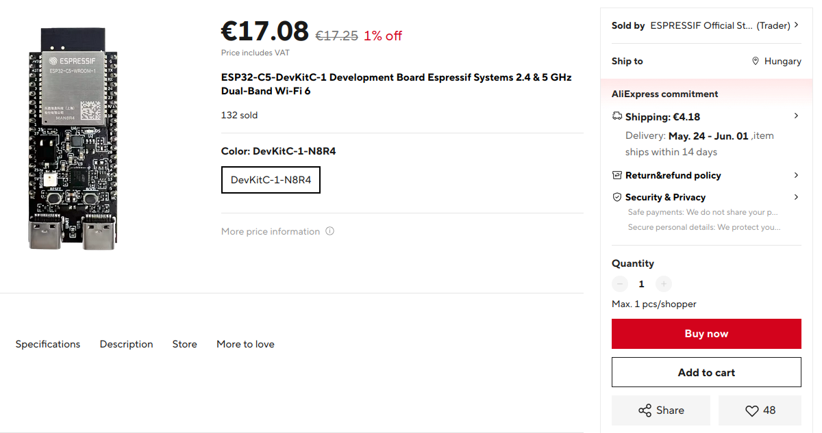
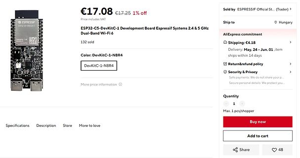
€17.25 1% off ESP32-C5-DevKitC-1 Development Board Espressif Systems 2.4 & 5 GHz Dual-Band Wi-Fi 6 132 sold Color: DevKitC-1-N8R4 DevKitC-1-N8R4 Sold by ESPRESSIF Official St... Trader Ship to Hungary AliExpress commitment Shipping: €4.18 Delivery: May 24 - Jun. 01, item ships within 14 days Return &
place.The compressors will withstand storage temperatures down to -35°C. Condensing temperatures: Max. 60°C at stable conditions and max. 70°C at peak load. Ambient temperatures: Min. -10°C, max. 55°C The BD compressor concept includes an electronic unit which features overload protection, battery protection
generated when the counter is equal to TOP. If TOP is updated to a value lower than count upon reaching MAX the counter restarts from BOTTOM. Figure 21-3. Periodic Interrupt Mode MAX and Event) Request TOP CNT BOTTOM TOP changed to CNT set to BOTTOM a value lower than CNT 21.3.3.1.2 Time-Out Check Mode In
_ R2134R2137 C EWR I . om om M200F U „ wu SYM H O T2035 T2037 Eíš Tzosa T2039 šgâgâooc Bëšëêfc I<9 132°” 1-C2070 1-4:-»24í<3 Q BFRQJA U U ._ N 5 f Bcseoc Caeoc ;:¦~BCae0C BCBBOC IIIII R22 __μ wm M C R2132 C207 51 391<2 “ R22o9 I' 5 1í1 4531? +12V R2267 I ` J ZZOD < __° C2072 mn D R21s3 -5.2V R235 5 _
plus Latch mit Konstantstromsenken, max. 120mA pro Ausgang Dimmung jedes einzelnen Kanals mit 6 Bit plus 12 Bit PWM möglich, kompatibel mit AS1112 mouser.com, hbe CAT4016 16 Bit-Schieberegister/Latch mit Konstantstromsenken(max. 100mA), günstig
Matrizentreiber mit Animationsspeicher, Diagnose und ChargePump AS1119 AS1130 I2C angesteuerter 132 LEDs Matrizentreiber mit Animationsspeicher, Scroll Funktion & Diagnose AS1130 AS1112 15V 16Kanal LED Treiber, max. 100mA pro Ausgang Dimmung jedes einzelnen Kanals mit 6 Bit plus 12 Bit PWM möglich
Connect an LED to this pin and to GND (“active high”). Use a series resistor to limit the current to max. 15mA (the absolute maximum being 25mA), e.g. 100Ω for a 3,3V supply and a standard LED. For higher loads (e.g. high-power LEDs or a relay) use an appropriate transistor. As with most microcontrollers
fills in its address. If no symbol with that name was found, it emits this dreaded error: (.text+0x132): undefined reference to `Foo' Google finds almost a million results for that message, but knowing how the linker operates makes it easy to understand and solve – since the symbol was not found in any
weniger Strom bzw. Leistung benötigen). Anonsten: http://slotbaer.de/slotbaer-projekte-digital/28-pd132-d124/29-d133.html
teilen dann erhält man 3 A. Wenn wir das jetz alles addieren kommen wir auf 3,9 Ampere die ich max benötigen würde. Da ich aber nicht alles voll aussteuer, dann kann man davon was abziehen. Et voila: pi mal Daumen 500mA
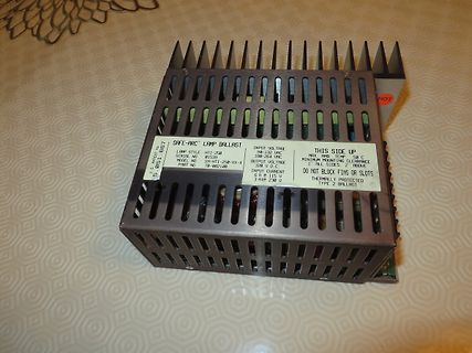
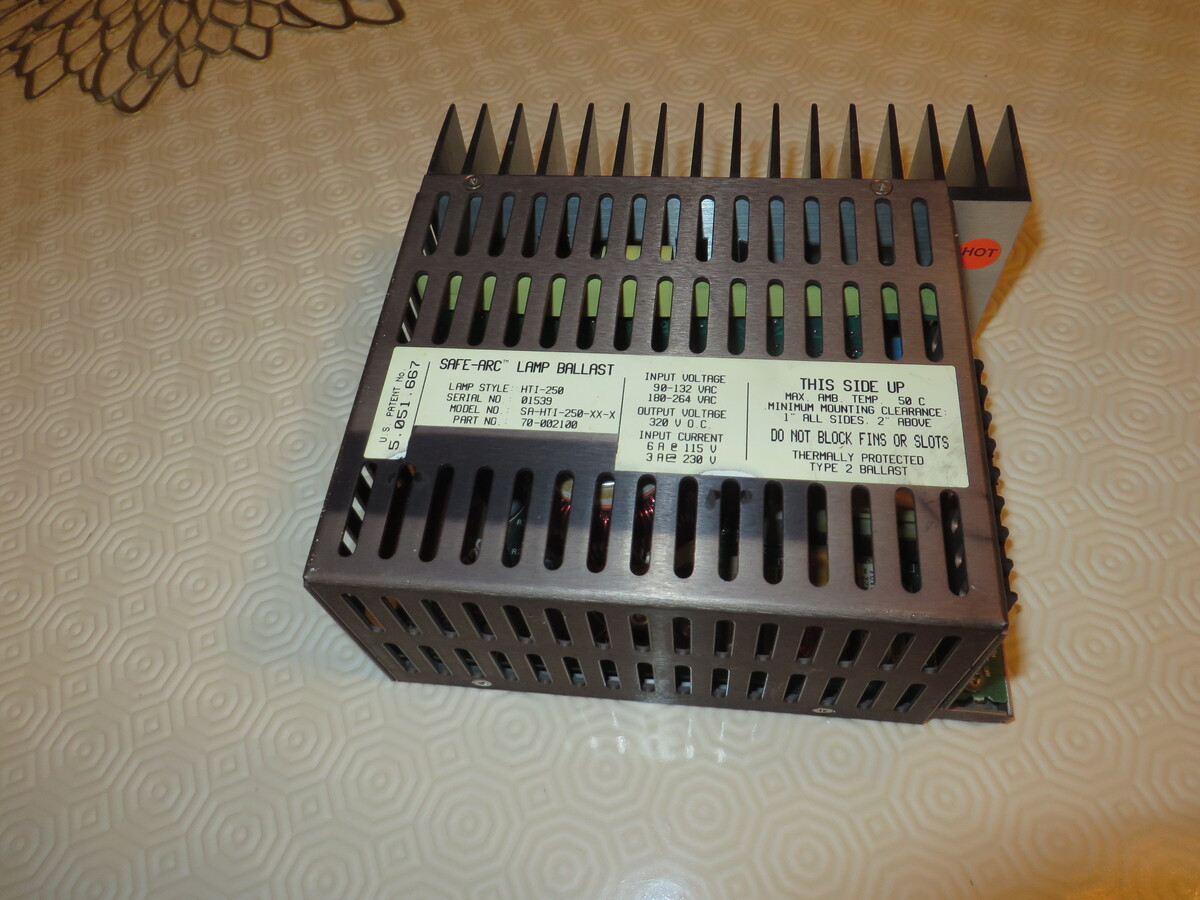
BALLAST
LAMP STYLE H11-250
SERIAL NO 01539
MODEL NO SA-H11-250-XX-X
PART NO 78-002100
INPUT VOLTAGE 98-132 VAC
180-264 VAC
OUTPUT VOLTAGE 520 V
INPUT CURRENT 6 A @ 132 V
3 A @ 230 V
THIS SIDE UP
MAX TEMP 50 °C
MINIMUM MOUNTING CLEARANCE 1" ALL SIDES 2" ABOVE
DO NOT BLOCK FINS OR SLOTS
THERMALLY PROTECTED
= 2.RF= 100 MHz,IF = 450 kHBW= 300 kHz, unless otherwise stated Note Parameter Conditions Min Typ Max Unit RF Input Frequency 64 108 MHz Input resistance Max / Min Gain 90 Input return loss 50 source 12 dB SSB Noise figure Max Gain 7.2 dB FIF 1.62 MHz 8.6 dB 1 Max Gain 106 dB Max Voltage Gain FIF
temperature range Temperature range -55 ~ +105 C -40 ~ +105 C -25 ~ +105 C WV 100 WV >100 Leakage current max. I = 0.01CV or 3 A whichever is greater (after 2 min) I = 0.03CV or 4 A whichever is greater (after 1 min) I = 0.02CV+15 A (after 5 min) Capacitance tolerance 20% at 120Hz, 20 C Capacitance > 1000 F : tan increases by 0.02 for each 1000 F from below value. Dissipation factor max. (at 120Hz, 20 C) WV 6.3 10 16 25 35 50 63 100 160~250 350~450 tan 0.28 0.24 0.20 0.16 0.14 0.12 0.10 0.08 0.15 0.20 WV 6.3 10 16 25 35 50~100 160 200~350 400 450 Low temperature characteristics (Impedance
AL CHICACTERIST ICS TA= 25°C, V IN2.0V, unless otherwise noted. SYMBOL PARAMETER CONDITIONS MIN TYP MAX UNITS IQ Quiescent Current VSHDN = 0.5V, FB= 2V 120 200 A VSHDN = 1.8V 7 15 A VIN Input Voltage Range 1.8 1.55 V 2.0 V Feedback Voltage 1.22 1.24 1.26 V Comparator Hysteresis 6 12.5 mV Feedback Pin
sentido horário, [MULTICHANNELDECODING],SOUNDFIELD[2CH],SOUND “VOL MIN”, “VOL 1” para “VOL 30”, “VOL MAX” aparecem. CONTROL [SURR] e [NAME] LED acendem. 4. Pressione a tecla [VIDEO 1] , todos os seguimentos apagarão. 5. Toda vez que pressionar a tecla [VIDEO 1] um conjunto de seguimento e LED acenderá
starten. Für diesen Fall reicht auch ein echt kleines Board. z.B was in der Größenordnung eines MAX1000 oder ähnliches: https://shop.trenz-electronic.de/de/TEI0001-04-FBC88A-MAX1000-IoT-Maker-Board-16kLE-32-MByte-SDRAM-8-MByte-Flash-6-15-x-2-5-cm Das hätte 64 Mal mehr Speicher auf dem Board als
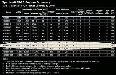
ADC. > Für diesen Fall reicht auch ein echt kleines Board. z.B was in der > Größenordnung eines MAX1000 oder ähnliches: > https://shop.trenz-electronic.de/de/TEI0001-04-FBC88A-MAX1000-IoT-Maker-Board-16kLE-32-MByte-SDRAM-8-MByte-Flash-6-15-x-2-5-cm Da würde ich mir eher das Spartan7 mini Board
Vb 1 7867 o t a l t ED ED ED s n I a b ED ED Va Vb a b ED ED Va Vb a b ED ED Va Vb 1 7867 ED ED ED max. 30 max. 30 max. 30 L N Va Vb L N Va Vb L N Va Vb 1 6481 L N 1 2 3 4 11 21 a1 b a2 b a3 b 1 7573 Va Vb Va Vb + E+ Va Vb Va Vb 1 4813 1 8783/ Va Vb 80 1 2 1 8789 LT 1 2 3 4 1 8759/ 1 8760 1 8753 S0251
customer needs, SIM8230G LGA, SIM8230G mPCIe or SIM8230G M.2 3042. Fibocom is following suit with the FG132 series, available in LGA, mPCIe, and M.2 3052. Semtech (Sierra Wireless) have an M.2 3042 design ready for integration. Last but not least, Quectel introduces the RG255C-GL in mPCIe and RM255C-GL
supports ESP32-P4 v1.0 chips. • New ports/analog port, initially supporting Analog Devices ADI MAX32690 microcontroller. • Over 20 new boards. [/c] Interessant ist auch das unter der URL https://blog.adafruit.com/2025/01/07/scott-and-ladyada-talk-circuitpython-2025-circuitpython-circuitpython2025

 Bild
Bild
 Bild
Bild
 Bild
Bild