using about 3 Hz higher frequency crystal than the received time signal frequency. For example, in DCF77 application a 77.503 kHz crystal resonates at the desired DCF77 77.500 kHz frequency when the load capacitor is missing. Table 1. Time-Signal System Frequencies Time-Signal System Location Antenna Frequency Recommended Crystal Frequency DCF77 Germany 77.5 kHz 77.503 kHz HGB Switzerland 75 kHz 75.003 kHz MSF United Kingdom 60 kHz 60.003 kHz WWVB USA 60 kHz 60.003 kHz JJY Japan 40 kHz and 60 kHz 40.003 kHz and 60.003 kHz BPC China 68.5 kHz
burden of CPU cycles. A rich set of 16-bit Analog-to-Digital Converters (ADCs), Operational Amplifiers (OpAmps) and a 12bit Digital-to-Analog Converter (DAC) replaces external analog front ends, lowering cost and noise. And with integrated SmartDMA, high-speed timers and industrial communications, the MCX
combines them. The MAU slashes cycle counts for trig functions, while integrated 3.2 Msps ADCs and OpAmps deliver cleaner, synchronized sensing, all inside a single package. SmartDMA and plentiful serial ports let you stream data without bogging down the core. Add in robust security, comprehensive motor
..................................................27 AddedADCDrivingSectionandFigure73throughFigure77.....28 12/14—Revision 0: Initial Version Added ADC Driving with Dynamic Power Scaling Section, Figure 78, Figure 79, and Figure 80..............................................29 Rev. B | Page 2 of 33
25601-0620 TRAN MOSFET N CHAN LL Q3 27103-1040 IC SM LM393 IC17, 26 27106-0644 IC SM TL074CD BI-FET OP AMP IC15 27106-0645 IC SM TO072CD DUAL BIFET OP AMP IC31, 32 27106-1080 IC SM OP07CS IC22 27106-1240 IC SM MCP602 IC28 27106-1250 IC SM MCP602 OP AMP IC28 27153-1120 IC SM MCP3201B 12 BIT ADC IC37 27161
geschikte bewaarplek voor het apparaat, idealiter in de buurt van een stopcontact. 2 Steek het apparaat op de wandhouder (afb. 6 ).3 Zet het ! WAARSCHUWING! apparaat met de wandhouder zo tegen de wand dat Wees bijzonder voorzichtig bij het reinigen op de turboborstel plat op de vloer ligt. 4 Markeer met trappen
Akodođedopromjenanauređaju EG-CONFORMITEITVERKLARING Hiermede verklaren wij, dat de genoemde machine, op beznašesuglasnosti,ovaIzjavapostajenevažećom. grond van zijn ontwerp en bouwwijze, evenals de door DEKLARACJA ZGODNOŚCI UE ons in omloop gebrachte uitvoeringen, aan de Niniejszym oświadczamy, my że koncepcja
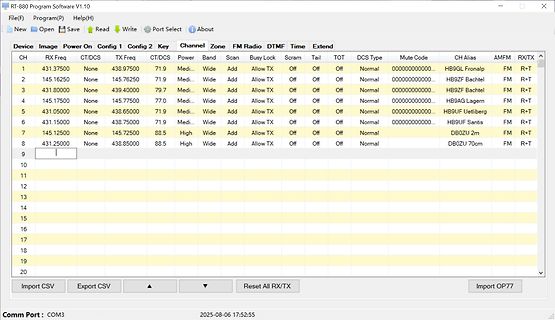
Es sind 2N0612. Das ist keine Typenbezeichnung, das ist nur das Marking. Suche doch mal nach IPB77N06S2-12 von Infineon.
Hersteller > befinden? Nein, die wäre schon erheblich größer. > Gibts eine Möglichkeit den Op Amp zu testen bevor ich den tausche? Man müsste vorher den Schaltplan aufnehmen.
500 in closed upper Short exposure at spaces. 0.5% to 1% fatal. Benzene Irritant, colorless anes- 2.77 Slight symptoms after 3,000 25 1.3 /7.1 At bottom. Industrial wastes, var- Combustible gas indi- (C 6 6) thetic. several hours expo- to nishes, solvents. cator. sure at 0.16% to 5,000 0.32%. 2% rapidly
. Und eine app, damit man die Farbe der blink-LEDs auch von den Malediven aus ändern kann. Ein DCF77 Empfänger und ein µC/Arduino würde allerdings auch reichen.
R. L. schrieb im Beitrag #7891707: > Ein DCF77 Empfänger und ein µC/Arduino würde allerdings auch reichen. Allerdings schrieb der OP: > Es dient als Übungsobjekt für meine bevorstehende Umschulung zum > Elektroniker für Geräte und Systeme.
Kontakt gewährleistet ist. Ihr habt mitbekommen, dass die Schrauben nur ein Provisorium sind und der OP das Punktschweißen möchte, sobald sichergestellt ist dass dahinter kein Fehler mehr ist. Und gepunktet ist das dann auch OK.
Generator Error -40°C ≤ T A 25°C -3.0 0 +3.0 deg /V Function Generator Gain T A 25°C, vs V OUT/F 60 77 95 °/V Notes: 1. Input is clamped by an internal 12 V Zener. 2. Applies to % of full scale (270°). 3. Deviation from nominal per Table 1 after calibration at 0° and 270°. December, 2012, Rev. 02 IL8190
current V = V - 0.2 V 200 250 µA CC CC(ON) I Device ON, V = 1 V q Quiescent current STBY 1.5 2 mA op Operating current Device ON, 3.5 5 mA V STBY= V RFmin V DIS> 1.85 V or DELAY I q Residual consumption > 3.5 V or LINE< 1.25 V 300 400 µA or VLINE= Vclamp High-side floating gate-drive supply ILKBOOT
section describes the different addressing modes supported by the AVR architecture. In the fig- ures, OP means the operation code part of the instruction word. To simplify, not all figures show the exact location of the addressing bits. Register Direct, Single Figure 9. Direct Single Register Addressing
Untersuchungen zur Selbstentladung von Nokia Handyakkus? Hier hat jemand an Rundzellen 3,8V auf 3,77V in 2 Jahren gemessen: https://accundu.de/selbstentladung-von-lithium-ionen-bei-lagerung-ein-selbstversuch
wöchentliche/tägliche (je nach Wichtigkeit) Funktionsprüfung Pflicht. Damit ist die Frage aus dem OP nicht sinnvoll.
wilt ver- cu‘s kunnen met de binden: Lidl Home app ver- bonden worden. 4.Selecteer op het tab- blad de optie 1.Druk 3 seconden „Apparaat toevoe- op de toets van de gen“. laadindicator (2) op De app scant de om- de Smart Battery om geving op beschikba- er zeker van te zikn re apparaten
Meterman 37XR (10,000 count) $250 10mV / mA 1mV / µA B&K 390A (4000 count) $380 2V max 500mV max Fluke 77 series III (3.5 digit) $400 6 mV / mA N/A Fluke 77 series IV (6000 count) $425 2mV / mA N/A Fluke 79 series III (3.5 digit) $375 11mV / mA N/A Fluke 177/179 series IV (6000 count) $430 2mV / mA N/A Fluke
load. Contact voltage Contact current Contact protection circuit Operating speed Expected life, min. op. 6 V DC 232 mA 0.2 F + 1k or diode 2 op./s 3×10 7 7 12 V DC 106 mA 0.2 F + 1k or diode 2 op./s 3×10 24 V DC 54 mA 0.1 F + 1k or diode 2 op./s 3×10 7 7 100 V DC 15 mA 0.1 F + 1k or diode 2 op./s 2×10 24 V DC 80 mA 0.2 F + 1k 2 op./s 3×10 7 100 V DC 20 mA 0.1 F + 1k or varistor 2 op./s 2×10 7 7 200 V DC 10 mA 0.1 F + 1k 2 op./s 2×10 (Notes) 1. When inrush current occurs in the capacitor load circuit or incandescent lamp load circuit
CBM-Screenmode > ist... Auf dem CBM muss man den Bildschirminhalt aber auch noch scrollen? Ob das vom OP berücksichtigt wurde?
Beitrag #7863619: > Auf dem CBM muss man den Bildschirminhalt aber auch noch scrollen? Ob > das vom OP berücksichtigt wurde? Wer lesen kann, ist klar im Vorteil. https://www.mikrocontroller.net/topic/577155?goto=7863620#7863460
48 (hexadecimal) (hexadecimal) 75 (decimal), 4B 74 (decimal), 4A H L H (hexadecimal) (hexadecimal) 77 (decimal), 4D 76 (decimal), 4C H H L (hexadecimal) (hexadecimal) 79 (decimal), 4F 78 (decimal), 4E H H H (hexadecimal) (hexadecimal) 8.4 Device Functional Modes Figure 16 and Figure 17 show the address
hast und wie toll das alles funktioniert. Da können wir > uns rein gar nichts davon kaufen und der OP erst recht nicht. Damit habe ich angedeutet, was damit möglich WÄRE. Niemand muss das machen. Und der OP kann natürlich damit etwas anfangen, denn: Markus W. schrieb im Beitrag #7832857: >
10-17 Op Amp Noise 10.5.6 Differential Op Amp Circuit Noise Taking the simplified equivalent op amp circuit from Paragraph 10.5.2 as the base, the noise equivalent of a differential op amp circuit is shown in
of operation to another. RESET (RST) Program Registers are set to default values G RO / DN RST NO_OP R PW Y/ DB T ST RS IDLE G Device waits for a PRO valid command toMA N/ initiate conversionC R_D h_n /W /AU DBY O _ ST RST MAN_Ch_n NO_OP NO_OP MANUAL STANDBY Channel n (STDBY) (MAN_Ch_n) M T _n N BY
LT1358/LT1359 Dual and Quad 25MHz, 600V/µs Op Amps U FEATURES DESCRIPTIO ■ 25MHz Gain Bandwidth The LT1358/LT1359 are dual and quad low power high ■ 600V/µs Slew Rate speedoperationalamplifierswithoutstandingACandDC ■ 2.5mA MaximumSupply Current
Kaum habe ich hier geantwortet schlagen meine Fenbeis zu. Jörg R. (solar77) 09.01.2025 01:07 Ralf X. (ralf0815) 09.01.2025 00:58 LOL Sie können es nicht lassen es jetzt für jeden deutlich zu machen, sollte der Moderation doch auch auffallen. Gut Nächt le
Köpfe ein. Nach dem 20ten Beitrag hauen sie sich eigentlich über alles und nichts die Köpfe ein. Das OP Thema ist dabei ziemlich unwesentlich.
alles auf einmal ändere, aber nicht weiß, woran es lag) 1. Ist die Ansteuerung zu langsam (per OP-Ausgang und 3,3k / 6,6k)? Aber der OP ist nicht der langsamste (3,5V/µs) und es sind nur einzelne Schaltvorgänge. Der halb leitende Zustand wird doch relativ schnell durchfahren. Wie schnell muss das
Spannungsregler? Es hat ja schon fast funktioniert ... Andere Idee: Kurze RC-Verzögerung nach dem 1. OP (damit er in Ruhe fertig schalten kann) und danach ein zweiter OP als Schmitt-Trigger. Es würde also ein TL062 reichen. Wolfram
load. Contact voltage Contact current Contact protection circuit Operating speed Expected life, min. op. 6 V DC 232 mA 0.2 F + 1k or diode 2 op./s 3×10 7 7 12 V DC 106 mA 0.2 F + 1k or diode 2 op./s 3×10 24 V DC 54 mA 0.1 F + 1k or diode 2 op./s 3×10 7 7 100 V DC 15 mA 0.1 F + 1k or diode 2 op./s 2×10 24 V DC 80 mA 0.2 F + 1k 2 op./s 3×10 7 100 V DC 20 mA 0.1 F + 1k or varistor 2 op./s 2×10 7 7 200 V DC 10 mA 0.1 F + 1k 2 op./s 2×10 (Notes) 1. When inrush current occurs in the capacitor load circuit or incandescent lamp load circuit
section describes the different addressing modes supported by the AVR architecture. In the fig- ures, OP means the operation code part of the instruction word. To simplify, not all figures show the exact location of the addressing bits. Register Direct, Single Figure 9. Direct Single Register Addressing

 Bild
Bild
 Bild
Bild
 Bild
Bild