SO8: plastic small outline package; 8 leads; body width 3.9 mm SOT96-1 D E A X c y HE v M A Z 8 5 Q A2 (A ) A A1 3 pin 1 index Lp L 1 4 e w M detail X b p 0 2.5 5 mm scale DIMENSIONS (inch dimensions are derived from the original mm dimensions) A (1) (2) (1) UNIT max. A1 A 2 A3 bp c D E e H E L Lp Q v w y Z 0.25 1.45 0.49 0.25 5.0 4.0 6.2 1.0 0.7 0.7 mm 1.75 0.10 1.25 0.25 0.36 0.19 4.8 3.8 1.27 5.8 1.05 0.4 0.6 0.25 0.25 0.1 0.3 o 8o 0.010 0.057 0.019 0.0100 0.20 0.16 0.05 0.244 0.039
Anschließen und keine USB-Dongel. Abgesehen davon, dass USB sau langsam ist (selbst bei USB3.2 Gen 3 4x4 Allrad Super advanced CDTI Version 4 Build 3.123a4), unterscheiden sich die Ergebnisse merklich. Und die optional dritte Erkenntnis: Schau dir nie an, wie schlecht eine SD-Karte tatsächlich ist.
Harald K. schrieb im Beitrag #8066720: > Dann zeig' doch mal eine 16-TB-SSD, die man sich gleich zweifach für das > heimische NAS leisten kann ... 2-fach? In ein NAS gehören 8-16 HDs!
= 3.3 V - 8.5 16.5 - 19 - 22 ns V CC = 4.5 V - 6.5 13 - 15 - 17 ns V CC = 6.0 V - 5.0 12.5 - 14.5 - 16.5 ns t enable time E to Z, E to Yn; see Fig. 12 [2] en V CC = 2.0 V - - 95 - 105 - 115 ns V CC = 3.0 V - - 90 - 100
steht, wird's FAT16 oder vielleicht noch FAT12 sein. FAT32 kam glaube ich später. Aber trotzdem, wie die Daten auf's Medium schreiben, sind z.B. Ordner erforderlich?
free disk size of drive "A:" (PC-Card) even if the user files are located in the RAM-Disk (drive "E:"). However "Memory_Card.jpg" from here https://www.mikrocontroller.net/topic/585660#8069147 seems to indicate that 745 kBytes are free on the PC-Card. So if in both cases the same content
about –174dBm/Hz (at a temperature of 290K). Thus the maximum received signal power is approximately 16dB below the thermal background noise level. -170 Thermal Noise -180 16 dB t s -190 e Received D ) Signal e H w /200 P B a ( t e -210 S -220 -2MHz -1MHz 0 1MHz 2MHz D eviation from med ia frequency Figure
S32K1xx Series Reference Manual, Rev. 13, 04/2020 NXP Semiconductors 259 MPU register descriptions 15.4.7.3 Diagram Bits 31 30 29 28 27 26 25 24 23 22 21 20 19 18 17 16 R E E E E E E E E e e R W R W R W R W r S U r S W 7 7 6 6 5 5 4 4 s 3 3 s 2 M M M M M M M M e M M e M R R Reset 0 0 0 0 0 0 0 0 0 1 1
RATED VOLTAGE RANGE (LETTER DENOTES CASE SIZE) Capacitance Rated Voltage DC (V ) R 85ºC Cap μF Code 4V (g) 6.3V (j) 10V (A) 16V (C) 20V(D) 25V(E) 50V(H) Code 0.15 154 A E 1.0 105 P A,M,P A A,M,P A 1.5 155 A E 2.2 225 P A,M,P A,M J 3.3 335 A,P A A N 4.7 475 A,M,P A,M,P A A A S 6.8 685 P A A W 10 106 A
wird neben dem geringen Preis auch die „hohe Leistungsfähigkeit“ des ADC hervorgehoben: [c] The 16 bit SAR ADC delivers high resolution and a high sampling rate of 2.4 MSPS in 16-bit mode and 3 MSPS in 12-bit mode, [/c] ### M5Stack Stamp-P4 - ESP32-P4-Modul Wer den ESP32-P4 bequem in einem Design
png) Bildquelle: https://www.oemsecrets.com/compare/S013?ccy=EUR&ctry=HU ### M5Stack Unit PoE-P4-ESP32-P4 mit Ethernet-Port um kleines Geld. Wer einen Ethernet-Port in ein System integriert, handelt sich verschiedenste „Lustigkeiten“ ein. Mit der in der Abbildung gezeigten und beim Hersteller
V V V V V V V V V V V V V V V V V V V V B_DDR3_DM0 C16 B_DDR3_DML C1000 B_DDR3_DM1 D21 B_DDR3_DMU B_DDR3_WEZ B-DDR3-WEZ R1018 22R*4 10NF B_DDR3_MCLK C13 B_DDR3_MCLK L T T P P M M J J G E A B 9G G F E E D D B B B13 B_DDR3_MCLKZ B_DDR3_CS0 B-DDR3-CS0 B_DDR3
xxx xxx 0.25 C OEM P/N 31 B 1.22 15.5 0.15 .610 . C 27.94 0 1.1 . 1.27 0 C .050 8 A A A A A B C D E F G H J K L M N P R T U V W Y A B C 1 0 5 7 8 2 L 5 0 0 1 1 E 1 2 3 E52P . 1 4 5 2 SUBSTRATE 5 0 7 6 5 6 0 5 7 GLOB 8 TOP 9 1 7 10 5 11 2 1 , 12 2 0 13 Cu ] 14 1 7 15 Cavity 1 4 STIFFENER 16 17 18 19
maximum-bandwidth option for systems where moving more data, faster, is the primary requirement. With 4 F-Tiles fully connected, it doubles the number of 116G transceivers previously available and delivers up to 80 high-speed transceivers, including 16 channels up to 116G PAM4, extending what is possible
> Kyocera AVX: 0201-Kondensatoren mit 10 µF. 4V Nennspannung! Naja, etwas knapp fuer 3.3V Aber okay fuer 2.5V Rails vermutlich nicht schlecht. Vanye
weniger große Fehler mitbringen. In einer vor wenigen Stunden an die Entwicklerschaft versendeten eMail kündigt Nordic nun eine Aktualisierung der Errata-Dokumente an, die die folgenden Chipfamilien betrifft: • nRF54L15 Errata • nRF54L10 Errata • nRF54L05 Errata • nRF54LM20A
bounded-latency scheduling, per-CPU execution paths, and a TCP/IP stack that respects both, all in the same address space, all under the same lock discipline. The kernel serves REST APIs and runs a web-based shell as ordinary preemptible tasks alongside deadline-scheduled control work. [/c] ### Mindgrove
–40°C ≤ T ≤ +125°C, IN OUT OUT J J unless noted. Parameter Symbol Min. Typ. Max. Units Conditions e , Output Noise Voltage — 400 — C = 10 µF n L (10 Hz to 100 kHz) — 260 — µVRMS C = 33 µF L = 100 mA L Ground Current in — 2 10 MIC29150/1/2/3 only µA Shutdown — — 30 VEN = 0.4V Reference - MIC29xx2/MIC29xx3
time 2 at which VOH is reached satisfies to V(t ) = 0.7 x V = V x (1 – e(-t / R C )) 2 DD DD 2 PU b leading to 2 = 1.2039729 x R PU x Cb 4. With tr= t2- 1 , it comes t = 0.8473 x R x C r PU b 5.2 Three-volt tolerant and five-volt tolerant Electrical characteristics defines
Ich bin da voll bei @ernst, und ich habe da mal etwas recherchiert. > Am Ende komnmt da ein Cortex-M4 oder ein Cortex-M7 bei heraus [...] > Echte 16-bit ADC mit DMA, SMID und DSP, 16-bit DAC um einen > OCXO zu führen. Na gut, eine Nummer kleiner, STM32L496. Der DAC hat nur 12 Bit und der Oszillator
irgendwer wollte HDMI haben ;) [pre]Display DOGS102: 0.25 mA typisch CPU STM32L496: < 4 mA TCXO KT2016K10000: < 1.5 mA GPS SAM-M10Q: 7 mA typisch; tracking DCF ???: t.b.d. diverse Pull-Down: 1.2 mA ALS SFH5711: ca. 0.5 mA RS-232 MAX3223E: < 1.3
oder SAM4 werden im Mittelfeld noch gelistet, sind aber auch tot. Den unteren Bereich scheinen eher die DSPIC zu dominieren, auch wenn da noch ein SAMC oder SAMD erscheint. Die DSPIC scheinen also alles andere
> Wenn man das Ding auf zB. 16MHz und einen Kern herunter bremst, dann ist > er plötzlich gar nicht mal sooo schlecht. Aber wer will das schon? ;-) Ein STM32L4 kann mit 6uA im Deepsleep verharren, aufwachen und dann kurz was
V V = 5.0V –55 C ( 4.0 –55 C < A 125 C CC G ) 16 A A o L 3.5 ( )1.60 +25 C O V T+ N 14 ( V E U +125 C L 3.0 R P O U 12 V O = 2.5V I1.50 S 2.5 C I E U G H P 10 L T 2.0 VT U 1.40 I O K VO = 0.4V L 1.5 8 C 1.30 1.0 6 4.50 4.75
3.00±0.1V 200±30mV -210±30mV available E HY2120-MB 4.45±0.025V 4.25±0.05V 2.25±0.08V 2.95±0.1V 200±30mV -210±30mV available A HY2120-NB 4.28±0.025V 4.08±0.05V 2.80±0.08V 3.00±0.1V 200±30mV -210±30mV available B HY2120-OB 4.25±0.025V 4.05±0.05V
- 2.1 mm max height SCALE 1.500 QUAD FLAT MODULE A 11.1 B 10.9 PIN 1 INDEX AREA 10.9 W (0.23) TYP E I V 1.9 C SEATING PLANE 0.72 E 0.1 R 4X 1.1 2X 7.8 0.55 24X 0.65 52X 0.45 P 15 16 28 29 24X 0.65 14 (0.25) TYP 30 1 0.05 SOLDER MASK 0.7 59 TYP 7.8 62 65 58 61 64 1.45 57 52X 0.35 TYP 60 63 0.15 C A
gezeigt. 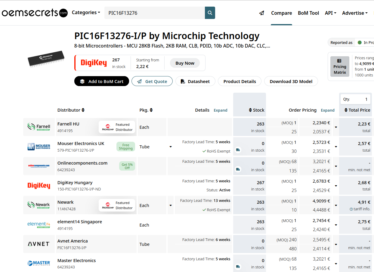 Bildquelle: https://www.oemsecrets.com/compare/PIC16F13276?ccy=EUR&ctry=HU ### Microchip – mit MPU System in Packages (SiPs) gegen DRAM-Probleme MicroChip bietet man seit einiger Zeit MPUs
[c] A vulnerable scenario arises when an application executes an AVX or SSE division instruction, e.g., the AVX instruction vdivss xmm3, xmm1, xmm2, and its operands (xmm1 and xmm2) contain confidential information. Now assume an attacker can execute code on the same system, for example, by running
±0.8 2.4 IIN IFS T A 0C to 85C (Note 4) -1.5 ±0.5 1.5 Linearity Error E L %FS IIN IFS T A -40C to 0C (Note 5) -1.5 ±0.5 1.5 IIN ±15A ~ ±50A, T =A0C to 85C (Note 4) -2.5 ±1.5 2.5 Total Error E TOT % RD IIN
Frequenzzähler ist Offset (→ [8]). Die LED leuchtet bei eingeschalte- abgeschaltet). tem DC-Offset. [16] BNC-Ausgangsbuchse OCV OUT [8] DC OFFSET-Potentiometer An dieser BNC-Ausgangsbuchse wird das den Nach Betätigung der zugehörigen Taste ON/OFF Oszillator steuernde Signal von ca. 0 V bis +4,5 V [7] lässt
in which the malfunction or failure of an electronic component could endanger human life or health (e.g. in accident prevention or lifesaving systems), it must therefore be ensured by means of suitable design of the customer application or other action taken by the customer (e.g. installation of protective
eee ee eee eee h e 3-15 3.4 DERLEAL SGGETOR: c c c a s u w e w e w e s s e n ceeeemeeeee cece BELG 3.4.1 Software deScription ciccescoccseeceseseecsevecesns 3715 3.4.2 RAM/ROM e e ee ee 3-16 3 . 4 . 3 I C b u s e e e e
... 0... cc c e e eee eee treet ee ene eae 14 1.3.4.3. Active filter... 0 . . . e e e e tee e e e eee ee 16 1.3.4.4. Analog-to-Digital convertor .. 2... 0 . 0 . 0 e e e e e e e eee 1B 1.3.5. Control section 2 . . .
specially optimized to gle Multiply-Add-Operation. It is calculated by multiplying exploit the Xilinx DSP48E1 blocks. For comparison with the minimum cycle time with the number of clock cycles Table I: Synthesis results 4,5E-16 4,01E-16 Architecture fMax Cycles LUTs DSPs 3,0E-16 Xilinx CoreGen 244 9 1253 13 FloPoCo FPPipeline 190 11 1508 7 1,5E-16 5,31E-17 PCS-FMA 231 5 5832 21 4,21E-17 1,65E-17 FCS-FMA 211 3 4685 12 0,0E+00 IEEE FP 68 Bit PCS FMA FCS FMA Double Figure 14: Average mantissa error in x[50] (arithmetic mean required to complete
adders that form a chain as shown in Fig. 3. The chain then S 1 S 0-1 S 2 S 0-3 feeds the last adder (i.e., Aacc), which accumulates the partial S 3 S 2-3 S results. By adopting a technique similar to log-sum [16], an S 4 S 0-7 N-adder chain reduces a block of 2 N items into a partial sum S 5 4-5 S 4-7 S
photopeak pulse height (channel) Pi:peak pulse height at the i-th reading n :total number of readings for 16 hours T ) +4 H ( D LT= 1.0 % I K E E H P +2 S I U R P T 0 5 10 15 I E TIME (h) N E O O T T -2 I H R P V T A -4 THBV4_0709EA Figure 7-9:Typical long-term stability of photomultiplier tube 7.2 Characteristics
n e 2 4 F F u a 6 0 7 0 W o C 1 C 1 5 r 4 I . a D D d , l T % o 1 1 5 P T 0 R T e r 7 R 1 a s k 3 0 3 1 3 1 2 s o 9 0 D N D N D N C o c R 3 1 1 1 Q M i a 4 4 e a D 4 D 4 F r c 8 k 1 1 μ a a R 1 5 . * * C 0 s t + N M C μ V 7 . 7 5 1 0 R 1 4 4 P 2 E 5 8 C n R 5 D 1 D D M 4 1 T 6 R 3 Q M 1 R 1 F V 1 7 3 C 4 6 T 2 R 1 D D N k A E R 2 I 7 F F 2 5 4 C 1 R 6 1 D M 2 F V 3 2 k C μ 5 1 C 1 n V R 1 3 2 U M 6 C 4 6 8 E 3 1 U F 1 F M C n E V R 1 1
while (1) { /* Toggle the LED on PA5 */ HAL_GPIO_TogglePin(LED_PORT, LED_PIN); /* Wait for some time (e.g. 500ms) to make the blink visible */ HAL_Delay(500); } /* USER CODE END 2 */ } /* USER CODE BEGIN 4 */ /* USER CODE END 4 */ /** * @brief GPIO Initialization Function * @param None * @retval None *
3.6V und eine Zyklen-Robustheit von 10¹⁴ verspricht. Der Speicher-Ausbau reicht dabei von 64 kb bis 4 Mb. Für die 4 Mbit-SKU MB85RS4MTPF-G-BCERE1 präsentiert sich die Bepreisung wie in der Abbildung gezeigt. 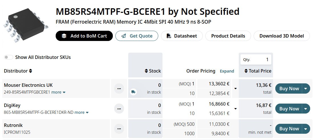 Bildquelle: https://www.oemsecrets.com/compare/MB85RS4MTPF-G-BCERE1
neuen Offerte aus dem Hause RECOM interessant finden. Sie bieten einen Eingangsspannungsbereich von 16.8VDC vis 137.5VDC, und weisen - wie in der Abbildung gezeigt - ein von unten kühlbares, in sich geschlossenes Metallgehäuse auf. 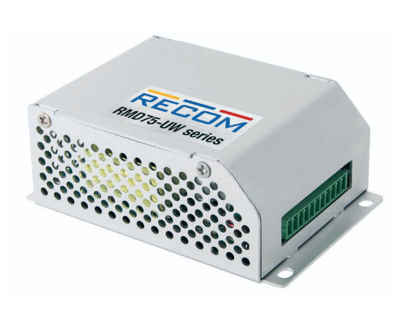 Bildquelle: RECOM ### Sciosense
Graphics Configuration -> LCD Control. Set the LCD Panel Type. Save this configuration by pressing “F4” and selecting “Yes” afterwards. 3.1.1.4 CPU i5-7300U To change the display resolution the following settings must be done. In the BIOS Setup mode choose the Advanced Menu select LVDS(eDP/DP) Configuration
Leitung nicht ausreichend isoliert oder beheizt war." https://grok.com/share/c2hhcmQtMw_df385870-d62e-4b67-9924-6452131be12c
oder ein Bogen? Etwas länger sollte es schon sein. https://quadro.burda-forward.de/ctf/1a459e71-2c12-4d10-a2a5-73497fdb5a7b.9fbfa04e-b2b0-4db8-aef1-e907c5c2232b.jpeg?im=RegionOfInterestCrop=(780,439),regionOfInterest=(312.5,206)&hash=eb7121683cefff16700c6da7fe7cec64c72f378a6e2afd19932097e3ad66d331
dass die Verbindungen innerhalb der Matrix nun ohne Koaxialkabel auskommen. 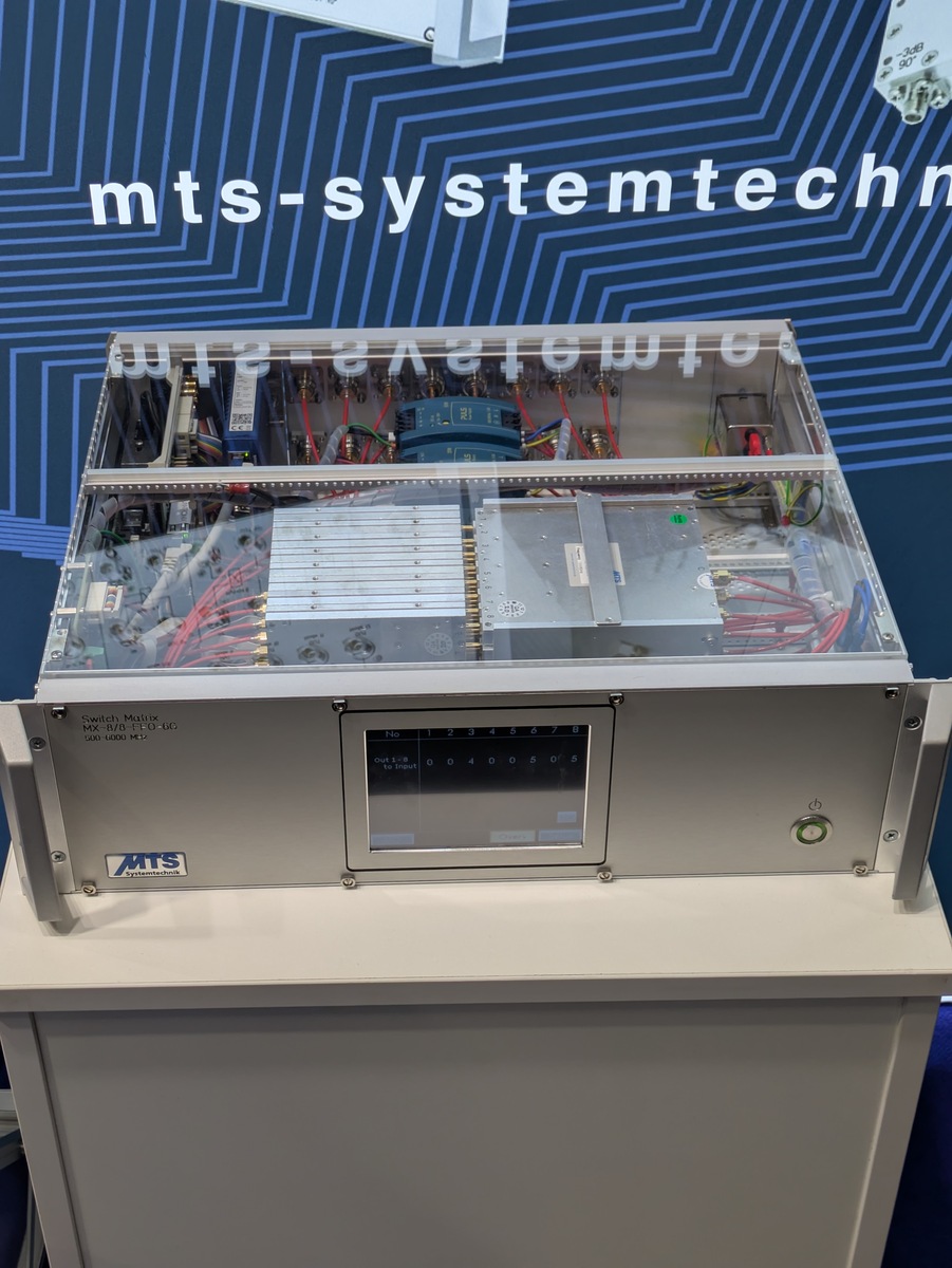 ### Siglent SNA5000X-E – Economy-Kombination aus VNA und Spektralanalysator HP führte mit dem legendären 4195A die Welt der Kombinationsgeräte ein, die sowohl Spektral- als auch VN-Analysator
ansässige Eurofins lanciert einen neuen Kammgenerator für das 18GHz-Band. 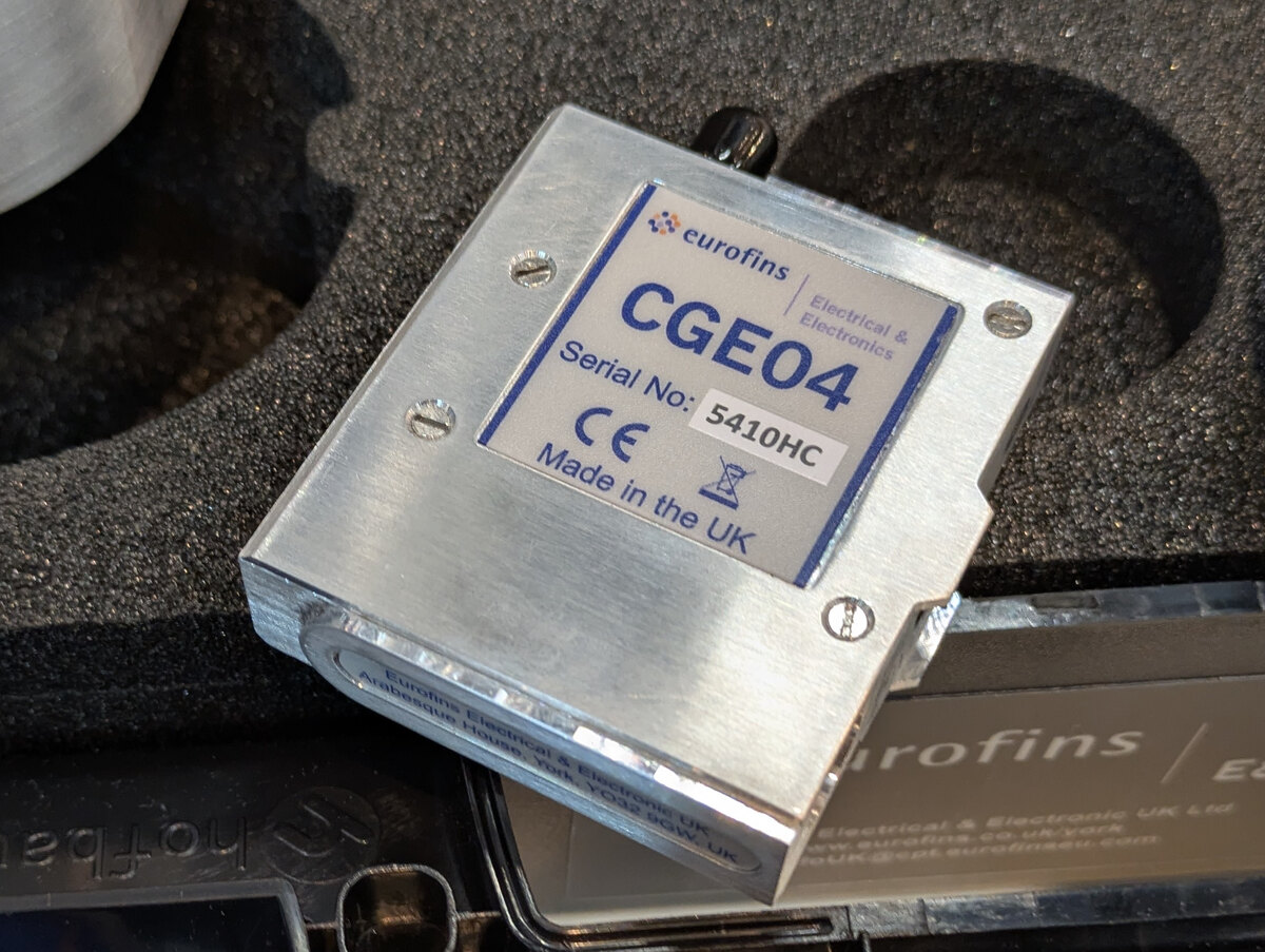 ### raditeq – PoE für die Sensorbox raditeq – das Unternehmen behauptet, schon 1999 die erste per LASER versorgte Sonde lanciert zu haben – zeigt eine neue Version seines Basisverstärkers. Relevant
(_C) A Figure 2. LED Forward Voltage vs. Forward Figure 3. Trigger Current vs. Temperature Current 16 10000 ) TA= 25_C D NORMALIZED TO PW IN>> 100 ms Z14 L A A 1000 R12 ( O T ( E T10 R 100 E U R C U 8 E C A R K 10 E 6 E G L R ,M T 4 R D ID 1 L ,T 2 IF 0.1 0 1 10 100 −40 −20 0 20 40 60 80 100 PW , LED
