-
PDF
lm5026.pdf
AUGUST 2005–REVISED MARCH 2010 Typical Performance Characteristics (continued) COMP Current vs INV PWM Comparator Voltage 800 -40°C 25°C ) 700 ( 85°C N R 600 125°C R C 500 M C 400 300 -0.100.000.10 0.200.30 0.40 0.50 INVERTING INPUT TO PWM COMPARATOR (V) Detailed Operating Description The LM5026 PWM
in „.lib datei einbinden“ · Analoge Elektronik und Schaltungstechnik ·
-
Datei
test23.asm
****************************************************** .def temp=r16 .def temp2=r17 .org $005 rjmp pwm ;pwm-emulator RESET: ldi temp, high(RAMEND) out SPH, temp ldi temp, low(RAMEND) out SPL, temp ;init Stack sei ldi temp,$20 out TIMSK,temp ldi temp,$00 out OCR1BH,temp ldi temp,$48 out OCR1BL,temp ldi
in „Simulator nicht in ordnung?“ · Mikrocontroller und Digitale Elektronik ·
-
Datei
test_pwm_t13.asm
" The extreme ... " im Fast PWM-Mode aussieht. ; ; *** FUSEBITS *** ; ; AUSLIEFERUNGSZUSTAND ( DEFAULT ) ; .include "tn13def.inc" .CSEG ;Code Segment .ORG $0000 ;Programm beginnt bei Adresse 0 ldi r16,0b10000011 ;Fast PWM Mode 3, OCRA non inverted out TCCR0A,r16 ; ldi r16,0b00000011 ;Prescaler 64 -> 580 Hz PWM Frequenz out TCCR0B,r16 ; ldi r16, 0x7F ; PWM Wert, HIER ÄNDERN!! out OCR0A, r16 ;Ports initialisieren sbi DDRB,PORTB0 ;PWM-Portpin als Ausgang... endlos: rjmp endlos
in „Spike sichtbar machen. Welches Oszilloskop kann dies leisten ?“ · Mikrocontroller und Digitale Elektronik ·
-
Datei
LED0_test.ino
#include <Wire.h> byte add = 11000100; // addresse byte PWM0 = 00000010; // PWM0 Register wahl byte PWM1 = 00000100; // PWM1 Register wahl byte PSC0 = 00000001; // PSC0 Register wahl byte PSC1 = 00000011; // PSC1 Register wahl byte LS0 = 00000101; // LS0 Register wahl byte LED = 00001110; // PWM0 -> LED 0.. PWM1 -> LED1 byte Daten1 = 10000000; // Daten 1 byte Daten2 = 00001111; // Daten 2 void setup() { Wire.begin(); Wire.beginTransmission(add); Wire.write(LS0); Wire.write(LED); Wire.endTransmission
in „PCA 9533 mit einem UNO ansteuern“ · Mikrocontroller und Digitale Elektronik ·
-
Datei
main.c
#include <avr/io.h> #include <avr/interrupt.h> #include <util/delay.h> #include "io.h" #include "pwm.h" #include "led.h" #include "uart.h" int main(void) { InitIO(); InitUART(); sei(); while(1){}; InitIO(); InitPWM(); InitUART(); /* _delay_ms(200); _delay_ms(200); _delay_ms(200); _delay_ms(200); LightOn
in „Atmega48 - UART als Interrupt“ · Mikrocontroller und Digitale Elektronik ·
-
Datei
Lambdacontroller_ai_claude_2.ino
) / 1023.0) * ADC_REF_VOLT * UBAT_DIV_FACTOR; // Kondensationsphase: 2V eff für 5s int CondensationPWM = (int)((2.0 / UBatt_V) * 255.0); if (CondensationPWM > 255) CondensationPWM = 255; if (CondensationPWM < 0) CondensationPWM = 0; analogWrite(HEATER_OUTPUT_PIN, CondensationPWM); HeaterOutput = CondensationPWM
in „Bosch CJ125 mit AVR AT90CAN64“ · Mikrocontroller und Digitale Elektronik ·
-
Datei
Lambdacontroller_ai_claude.txt
) / 1023.0) * ADC_REF_VOLT * UBAT_DIV_FACTOR; // Kondensationsphase: 2V eff für 5s int CondensationPWM = (int)((2.0 / UBatt_V) * 255.0); if (CondensationPWM > 255) CondensationPWM = 255; if (CondensationPWM < 0) CondensationPWM = 0; analogWrite(HEATER_OUTPUT_PIN, CondensationPWM); HeaterOutput = CondensationPWM
in „Bosch CJ125 mit AVR AT90CAN64“ · Mikrocontroller und Digitale Elektronik ·
-
PDF
ht1632cv130.pdf
drain output and =00 8 COM option ab=11: P-MOS open drain output and 16 COM option 1 0 0 101X-0000-X C PWM 1/16 duty 1 0 0 101X-0001-X C PWM 2/16 duty 1 0 0 101X-0010-X C PWM 3/16 duty 1 0 0 101X-0011-X C PWM 4/16 duty 1 0 0 101X-0100-X C PWM 5/16 duty 1 0 0 101X-0101-X C PWM 6/16 duty 1 0 0 101X-0110-X C PWM 7/16 duty 1 0 0 101X-0111-X C PWM 8/16 duty PWM Duty 1 0 0 101X-1000-X C PWM 9/16 duty 1 0 0 101X-1001-X C PWM 10/16 duty 1 0 0 101X-1010-X C PWM 11/16 duty 1 0 0 101X-1011-X C PWM 12/16 duty 1 0 0
in „8x8 RGB Matrix Ansteuerungsproblem“ · Mikrocontroller und Digitale Elektronik ·
-
PDF
MEGA48V_88V_168V.pdf
correct PWM mode, the compare units allow generation of PWM wave- forms on the OC1x pins. Setting the COM1x1:0 bits to two will produce a non-inverted PWM and an inverted PWM output can be generated by setting
in „analog comparator interrupt probleme mit atmegas“ · Mikrocontroller und Digitale Elektronik ·
-
PDF
Mega32.pdf
correct PWM mode, the compare units allow generation of PWM waveforms on the OC1x pins. Setting the COM1x1:0 bits to 2 will produce a non- inverted PWM and an inverted PWM output can be generated by setting the
in „AVR Timer/Counter Zeit berechnen“ · Mikrocontroller und Digitale Elektronik ·
-
Datei
Sprungantwort.c
0; char buffer[7]; #define OCR_VAL (F_CPU / INTERRUPTS_PER_SECOND -1) //--------------------------PWM-------------------------------- void PWM_init (void){ TCCR0 = (1<<WGM00)|(1<<COM01)|(1<<CS01); // PWM,8 bit.phase correct, } //-------------------------ADC----------------------------------------- static
in „UART in ISR (Mega32)“ · Mikrocontroller und Digitale Elektronik ·
-
Datei
Atmega8-V5.bas
Config Portd.6 = Output 'Pin 12 LED Mode 2 Config Portd.7 = Output 'Pin 13 LED Mode 3 Config Timer1 = Pwm , Pwm = 8 , Compare A Pwm = Clear Up , Compare B Pwm = Clear Up , Prescale = 1 Config Timer2 = Pwm , Pwm = On , Compare Pwm = Clear Down , Prescale = 1 Enable Timer1 Enable Timer2 Start Timer1 Start Timer2 'Die PWM-Register zuweisen Rot Alias Compare1a Gruen Alias Compare1b Blau Alias Ocr2 'Interrupts global freigeben Enable Interrupts Dim Rot_0 As Byte Dim Gruen_0 As Byte Dim Blau_0 As Byte Dim Fader_mode As
in „Kerzenlicht oder Kaminfeuer in Bascom“ · Mikrocontroller und Digitale Elektronik ·
-
Datei
LCD_PWM_ATtiny2313.c
include <util/delay.h> #include <stdlib.h> #include <avr/pgmspace.h> void timer_init() { //TIMER 4 PWM Init TCCR0A |= (1<<COM0A1) | (1<<WGM00); // PWM 0A TCCR1A |= (1<<COM1A1) | (1<<COM1B1) | (1<<WGM10); // PWM 1A,1B TCCR0B |= (1<<CS00);// kein Vorteiler an T0 für max. Teiler CSx2 setzen TCCR1B |= (1
in „ATtiny2313 / LCD2x16 / String Ausgabe fehlerhaft“ · Mikrocontroller und Digitale Elektronik ·
-
Datei
Master.c
power_reduction = (1<<PRTIM1) | (0<<PRTIM0) | (1<<PRUSI) | (0<<PRADC); //Set the modus of the counter - Set PWM, phase correct timer0_modus = (0<<COM0A1) | (0<<COM0A0) | (1<<COM0B1) | (0<<COM0B0) | (1<<WGM01) | (1<<WGM00); //Set the prescaler of the PWM clock, no pre-sclaer set. Counter (8bit) overflows (1000000
in „ATTINY84A Rechnung in C“ · Mikrocontroller und Digitale Elektronik ·
-
Datei
PWMVersuch.asm
r21 ; .def rl2H = r22 ; .def rl3H = r23 ; .def tim1 = r24 ; .def tim2 = r25 ; .equ OFL = 2 ; .equ PWM1 = PB2 ; .equ PWM21 = PB3; .equ PWM3 = PB4 ; .equ Time = 40 ; rjmp Reset ; Springe zur Initialisierung reti reti reti reti reti reti reti reti rjmp Timer0_OVF Reset: ldi WorkH, high(Ramend) out SPH,
in „Atmega 16 Interrups“ · Mikrocontroller und Digitale Elektronik ·
-
Datei
spindle_control.c
include "spindle_control.h" #include "protocol.h" #include "gcode.h" void spindle_init() { SPINDLE_PWM_DDR |= (1<<SPINDLE_PWM_BIT); // Configure as PWM output pin. SPINDLE_DIRECTION_DDR |= (1<<SPINDLE_DIRECTION_BIT); // Configure as output pin. spindle_stop(); } void spindle_stop() { #ifdef RC_SERVO_INVERT
in „Projekt: SerialComCNC Serielles Frontend für CNC GRBL mit ATMega“ · Projekte & Code ·
-
Datei
PDM_2SpgE.ino
Pulsdauermodulation * Arduino Micro * Ausgang OCR1B muss invertiert sein */ #include <util/atomic.h> #define F_PWM 62500L //Hz #define PRESCALER 1 #define TIMER_RELOAD ((F_CPU / ( PRESCALER * F_PWM) -1)) //Fast PWM //Variablen volatile uint16_t Frequenz; volatile uint8_t Amplitude, Amplitude_inv; static uint16_t
in „Arduino Micro SPWM“ · Mikrocontroller und Digitale Elektronik ·
-
Datei
SinusoidalBLDC_v1.2.c
PreCondition: None. Input: None. Output: None. Side Effects: None. Overview: InitMCPWM, intializes the PWM as follows: 1. FPWM = 20000 hz 2. Complementary PWMs with center aligned 3. Set Duty Cycle to 0 for complementary, which is half the period 4. Set ADC to be triggered by PWM special trigger 5. Configure
in „Probleme beim Importieren von Projekten nach Linux MPLAB_X mit MPLAB®XC16 Compiler“ · Mikrocontroller und Digitale Elektronik ·
-
Datei
Motor1.c
7 (Fast PWM) (Aus Tabelle 14-8) TCCR0B |= (1<<WGM02); //Mode 7 (Fast PWM) (Aus Tabelle 14-8) TCCR0B |= ((0<<CS02) | (0<<CS01) | (1<<CS00)); //Kein Teiler (Aus Tabelle 14-9) OCR0A=100; /*Fast PWM mit Timer1*/ TCCR1A
in „zwei if-Anweisungeg funktionieren nicht zusammen“ · Mikrocontroller und Digitale Elektronik ·
-
PDF
BLDC_Controller.pdf
GVDD_B GVDD_A 35 BST_A 50V 100n Induktivität 0.40uH A FAULT PIIC302 OTW BST_A PII34035 PVDD PC2P1 PWM_A PIIC403 FAULT PVDD_A PII33034 OUT_A0 L2 P1 NRESET0 PIIC104 PWM_A OUT_A PIIC1033 NLGND0 PL0 PL02 CO RESET_A PIIC105 RESET_A GND_A PIIC1032 GND_A 600 Ohm @ 100MHz V1 0R PWM_B PIIC106 PWM_B GND_B PIIC1031
in „Tipps Platinenlayout“ · Platinen ·
-
PDF
ATM16_doc2466.pdf
correct PWM mode, the compare units allow generation of PWM wave- forms on the OC1x pins. Setting the COM1x1:0 bits to 2 will produce a non-inverted PWM and an inverted PWM output can be generated by setting the
in „ISP - Pinbelegung“ · Mikrocontroller und Digitale Elektronik ·
-
Datei
AEMA_PWM_24Hz.asm
.INCLUDE "tn461Adef.inc" ; R16 and R17 are used for calculations ; R30 Z-Buffer is used as pwm position pointer ; R31 Z-Buffer is used as pwm position pointer .CSEG ; Reset and interrupt vectors .ORG 0x0000 RJMP RESET .ORG OVF1addr RJMP Timer1_Reload .ORG 0x0013 RESET: LDI R16, (1 << CLKPCE)
in „PWM für langsame periodische Signale“ · Mikrocontroller und Digitale Elektronik ·
-
PDF
drm-7710-v1_de_screen.pdf
Motor 2 IN 2 1 Pin 5: Strommeswiderstandsanschluss oder die ERROR-Status Pin 6: Enable Motor1 on (PWM) Pin 7: 1ERROR-Status oder Strommeswiderstandsanschluss Pin 8: Enable Motor2 on (PWM) Pin 9: GND Pin 10: VCC 5VPin 10: VCC 5V 1–Auswahl erfolgt durch entsprechende Jumper auf der Platine. Die Pinbelegung
in „2x Motoren (12V / 2A) mit PWM ansteuern (µC PIC)“ · Mikrocontroller und Digitale Elektronik ·
-
PDF
ATMega_48_88_168.pdf
correct PWM mode, the compare units allow generation of PWM waveforms on the OC1x pins. Setting the COM1x1:0 bits to two will produce a non-inverted PWM and an inverted PWM output can be generated by setting the
in „I2C/TWI TWBR > 10 warum?“ · Mikrocontroller und Digitale Elektronik ·
-
PDF
ATmega32.pdf
correct PWM mode, the compare units allow generation of PWM wave- forms on the OC1x pins. Setting the COM1x1:0 bits to 2 will produce a non-inverted PWM and an inverted PWM output can be generated by setting the
in „STK500 als ISP“ · Mikrocontroller und Digitale Elektronik ·
-
PDF
Ateme16.pdf
correct PWM mode, the compare units allow generation of PWM wave- forms on the OC1x pins. Setting the COM1x1:0 bits to 2 will produce a non-inverted PWM and an inverted PWM output can be generated by setting the
in „Atmega16 und spi bus“ · Mikrocontroller und Digitale Elektronik ·
-
PDF
Ateme16.pdf
correct PWM mode, the compare units allow generation of PWM wave- forms on the OC1x pins. Setting the COM1x1:0 bits to 2 will produce a non-inverted PWM and an inverted PWM output can be generated by setting the
in „Atmega16 und spi bus“ · Mikrocontroller und Digitale Elektronik ·
-
Datei
levitation.txt
und aktuellem Ist-Wert gebildet. Die Addition beider Anteile bildet den Stellwert die Pulsbreite des PWM-Signals. Das Stellglied der Elektromagnet auch Aktuator genannt Eine Ferritkernspule dient als Stellglied innerhalb des Regelkreises. Ein mit 32 kHz pulsbreitenmoduliertes Signal (PWM) steuert die Leistungstreiber
in „Antigravitation“ · Mikrocontroller und Digitale Elektronik ·
-
Datei
FET140_demolist_C.txt
ACLK fet140_ta_15.c - Timer_A, Toggle P1.1/TA0, Up/Down Mode, HF XTAL ACLK fet140_ta_16.c - Timer_A, PWM TA1-2, Up Mode, DCO SMCLK fet140_ta_17.c - Timer_A, PWM TA1-2, Up Mode, 32kHz ACLK fet140_ta_18.c - Timer_A, PWM TA1-2, Up Mode, HF XTAL ACLK fet140_ta_19.c - Timer_A, PWM TA1-2, Up/Down Mode, DCO SMCLK
in „MSP430 UART Baudrate einstellen“ · Mikrocontroller und Digitale Elektronik ·
-
Datei
burst3.asm
0X2A ;PULSE WIDTH MODULATION REPS PWMCNT EQU 0X28 ;PULSE WIDTH MODULATION COUNTER REDPWM EQU 0X2B ;PWM TEMPORARY RED WORK COUNTER GRNPWM EQU 0X2C ;PWM TEMPORARY GREEN WORK COUNTER BLUPWM EQU 0X2D ;PWM TEMPORARY BLUE WORK COUNTER RANDOM1 EQU 0X31 ;FIRST BYTE OF RANDOMISER SHIFT REGISTER RANDOM2 EQU 0X32
in „12F629 LED Ansteuern in versch. Helligkeitsstufen“ · Mikrocontroller und Digitale Elektronik ·
-
 Bild
Bild
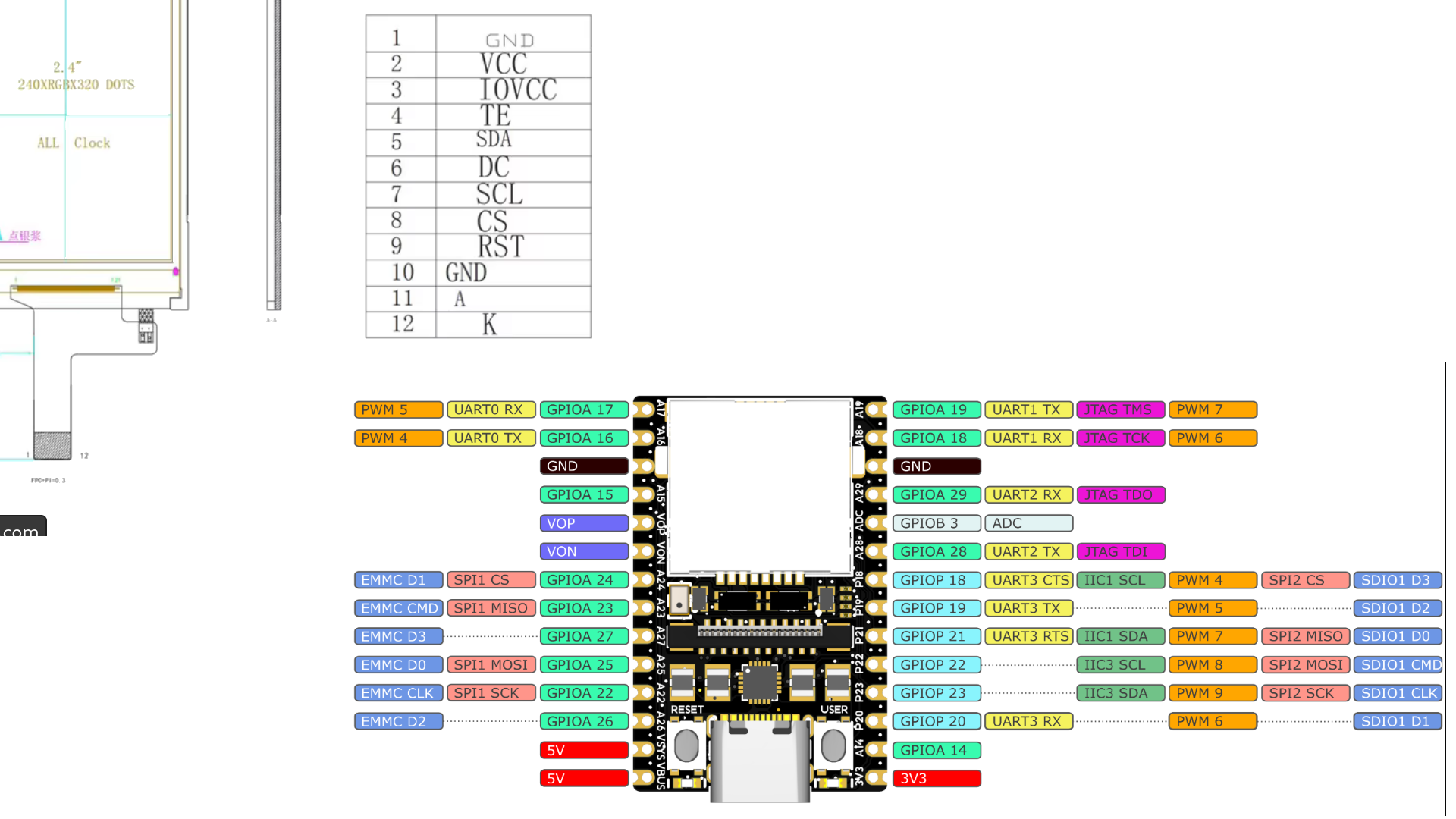
Pinbelegung einer Leiterplatte
2.4" 240XRGBX320 DOTS 1 GND 2 VCC 3 IOVCC 4 TE 5 SDA 6 DC 7 SCL 8 CS 9 GND 10 11 A 12 ALL Clock PWM 5 UART0 RX GPIOA 17 UART1 TX JTAG TMS PWM 7 PWM 4 UART0 TX GPIOA 16 GPIOA 18 UART1 RX JTAG TCK PWM 6 GND GPIOA 15 VOP GPIOA 29 UART2 RX JTAG TDO VON GPIOA 28 PWM 5 EMMC D1 SPI1 CS GPIOA 24 UART2 TX
in „LicheeRV Nano - Display Pinout / Wiring für SPI“ · Mikrocontroller und Digitale Elektronik · · Screenshots
-
Datei
inverter.ino
/* */ #define PWM_CT2A 11 //OC2A #define PWM_CT2B 3 //OC2B #define maxpwm 127 void ct2_init() { pinMode(PWM_CT2A, OUTPUT); pinMode(PWM_CT2B, OUTPUT); TCCR2A = (1 << COM2B1) |(1 << COM2B0) | (1 << COM2A1) | (1 << WGM20); //fast PWM TCCR2B = (1 << CS20); // prescaler 0 OCR2A = 0; OCR2B = 255; // pwm value } void setup() { pinMode(LED_BUILTIN, OUTPUT); Serial.begin(115200); ct2_init(); } void setct(uint8_t data) { uint8_t ld = constrain
-
PDF
Preview_of__io.h_.pdf
/io76c711.h> #elif defined (__AVR_AT86RF401__) # include <avr/io86r401.h> #elif defined (__AVR_AT90PWM1__) # include <avr/io90pwm1.h> #elif defined (__AVR_AT90PWM2__) # include <avr/io90pwmx.h> #elif defined (__AVR_AT90PWM2B__) # include <avr/io90pwm2b.h> #elif defined (__AVR_AT90PWM3__) # include <avr/io90pwmx.h> #elif defined (__AVR_AT90PWM3B__) # include <avr/io90pwm3b.h> #elif defined (__AVR_AT90PWM216__) # include <avr/io90pwm216.h> #elif defined (__AVR_AT90PWM316__) # include <avr/io90pwm316.h> #elif defined (__AVR_AT90PWM81__) # include
in „µC am Mac mit C programmieren“ · Mikrocontroller und Digitale Elektronik ·
-
PDF
ATMega164_324_644_1284pa.pdf
correct PWM mode, the compare units allow generation of PWM wave- forms on the OCnx pins. Setting the COMnx1:0 bits to two will produce a non-inverted PWM and an inverted PWM output can be generated by setting
in „Hilfe bei AD-Wandler!“ · Mikrocontroller und Digitale Elektronik ·
-
PDF
LPC_2119_2129_Datenblatt.pdf
rate, by resetting the count upon match. The other match register controls the PWM edge position. Additional single edge controlled PWM outputs require only one match register each, since the repetition rate is the same for all PWM outputs. Multiple single edge controlled PWM outputs
in „LPC 2129 Versorgungsspannung via PIN“ · Analoge Elektronik und Schaltungstechnik ·
-
PDF
UM_10120_LPC213x_User_Manual.pdf
100 (PWM rate) when a match event occurs. MR1 = 41, MR2 = 78 (PWM2 output) Control bits PWMSEL2 and PWMSEL4 are set. MR3 = 53, MR4 = 27 (PWM4 output) MR5 = 65 (PWM5 output) PWM2 PWM4 PWM5 0 27 41 53 65 78 100
in „Zeichen im Interrupt empfangen“ · Mikrocontroller und Digitale Elektronik ·
-
PDF
UM10120_1.pdf
100 (PWM rate) when a match event occurs. MR1 = 41, MR2 = 78 (PWM2 output) Control bits PWMSEL2 and PWMSEL4 are set. MR3 = 53, MR4 = 27 (PWM4 output) MR5 = 65 (PWM5 output) PWM2 PWM4 PWM5 0 27 41 53 65 78 100
in „Baudrate Abtastfrequenz“ · Mikrocontroller und Digitale Elektronik ·
-
Datei
nex_4_pwm_tb.vhd
library IEEE; use IEEE.STD_LOGIC_1164.ALL; use ieee.numeric_std.all; entity nex_4_pwm_tb is end nex_4_pwm_tb; architecture Behavioral of nex_4_pwm_tb is COMPONENT nex_4_pwm Port( clk : in std_logic; -- clock led : out std_logic_vector(15 downto 0); sw : in std_logic_vector(15 downto
-
PDF
LMD18200.pdf
LMD18200 LMD18200 www.ti.com SNVS091F –DECEMBER 1999–REVISED APRIL 2013 APPLICATION INFORMATION TYPES OF PWM SIGNALS The LMD18200 readily interfaces with different forms of PWM signals. Use of the part with two of the more popular forms of PWM is described in the following paragraphs. Simple, locked anti-phase
in „Motortreiber LMD18200“ · Analoge Elektronik und Schaltungstechnik ·
-
PDF
LT3474.pdf
PWM RATIO = = 300 1 tiedthere. UsetheC-RCstring(tiedtotheV pCn)shown 40µs inFigure6forproperoperationduringstart-up.Whenthe DIM RATIO= 1 • 00 = 3000 1 PWM REF 60Hz TO PWM 10kHz R1 LT3474 LT3474 ADJ LED
in „3W Luxeon Led energiesparend dimmen“ · Mikrocontroller und Digitale Elektronik ·
-
PDF
mega644.pdf
correct PWM mode, the compare units allow generation of PWM wave- forms on the OCnx pins. Setting the COMnx1:0 bits to two will produce a non-inverted PWM and an inverted PWM output can be generated by setting
in „AVR Controller braucht zu viel Strom“ · Mikrocontroller und Digitale Elektronik ·
-
PDF
AtMega644P_Datasheet.pdf
correct PWM mode, the compare units allow generation of PWM wave- forms on the OCnx pins. Setting the COMnx1:0 bits to two will produce a non-inverted PWM and an inverted PWM output can be generated by setting
in „Alkoholmessgerät programmieren“ · Mikrocontroller und Digitale Elektronik ·
-
PDF
ATmegaXX4.pdf
correct PWM mode, the compare units allow generation of PWM wave- forms on the OCnx pins. Setting the COMnx1:0 bits to two will produce a non-inverted PWM and an inverted PWM output can be generated by setting
in „Atmega644PA Timer3“ · Mikrocontroller und Digitale Elektronik ·
-
PDF
atmega644.pdf
correct PWM mode, the compare units allow generation of PWM wave- forms on the OCnx pins. Setting the COMnx1:0 bits to two will produce a non-inverted PWM and an inverted PWM output can be generated by setting
in „SPI-Kommunikation Atmega644 - ADS1118“ · Mikrocontroller und Digitale Elektronik ·
-
Datei
PWMtest.asm
;------------------------------------------------------------------------- ; Projekt: PWM ; Anfang: 25.07.2004 ; Progrmmierer: Dirk Broßwick ; Beschreibung: Erzeugung einer 8-Kanal-PWM auf den PortC eines ; Mega8 ;-------------------------------------------------------------------------
in „wiedereinmal PWM“ · Mikrocontroller und Digitale Elektronik ·
-
Datei
teeest.c
tx_buff[1]) = data; while( DATA_INT ); // until tx done } ISR( TIM0_COMPA_vect ) { if( OCR0A != 0xFF ) PWM = 1; // LED on } ISR( TIM0_OVF_vect ) { if( OCR0A != 0x00 ) PWM = 0; // LED off } void pwm_init( void ) { OCR0B = 0xFF; // 0% TIMSK0 = 1<<OCIE0A | 1<<TOIE0; TCCR0A = 1<<COM0B1 | 1<<COM0B0; // set data
in „mehrere MC seriell über Datenbus verbinden (1Draht)“ · Projekte & Code ·
-
Datei
Version_2.0.c
//y=(pulseInUs/22)-509; PWM_set(y); newPulseWith = 0; } if (i==1000) { i=0; printf("PWM=%6d \n",y); } } } // set_mux stellt den Display-Multiplexer auf LEDs, Ampel oder Siebensegmentanzeige void set_mux (uchar mux) { PORTB=mux
in „Pulsweitenmessung“ · Mikrocontroller und Digitale Elektronik ·
-
Datei
spi_slave.cpp
, PWM_VAL_INIT, BATTERY_INIT}; //references to registers volatile uint8_t& motor_mode = *regs; volatile uint8_t& pwm_val = *(regs+1); volatile uint8_t& battery_val = *(regs+2); volatile uint8_t spi_mode =
in „SPI Attiny44“ · Mikrocontroller und Digitale Elektronik ·
-
 Bild
Bild
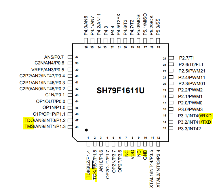
Pinbelegung des SH79F1611U Mikrocontrollers
/AN11 P4.4 P4.5/T2EX P4.6/T3 P4.7/T2 P5.0/MOSI P5.1/MISO P5.2/SCK P5.3/SS P2.7/T1 P2.6/T0/FLT P2.5/PWM21 P2.4/PWM11 P2.3/PWM01 P2.2/PWM2 P2.1/PWM1 P2.0/PWM0 P3.0/PWM3 P3.1/INT40/RXD P3.2/INT41/TXD P3.3/INT42 XTAL2/INT43/P3.4 XTAL1/INT44/P3.5 NC NC GND VDD NC OP2P/P3.6 OP2N/P3.7 AN10/P1.7 TCK/RST/P1.5
in „SH79F1611U Prozessor ist ein Clone von was?!“ · Mikrocontroller und Digitale Elektronik · · Screenshots
-
Datei
Sinus.vhd
UNISIM.VComponents.all; library IEEE; use IEEE.std_logic_1164.ALL; use IEEE.numeric_std.ALL; entity SinusPWM is Port ( clk : in STD_LOGIC; pwmout : out STD_LOGIC; Data_in : in STD_logic); end SinusPWM; architecture Behavioral of SinusPWM is signal sinus : std_logic_vector(7 downto 0); signal sinusplusoffset
in „Sinustabelle mit 2 Geschwindigkeiten“ · FPGA, VHDL & Co. ·