-
PDF
HX8238A.pdf
output 0 0 1 us 0 1 3 us 1 0 5 us 1 1 7 us Table 9. 10 Delay amount of the source output EQ2-0: Sets the equalizing period. EQ2 EQ1 EQ0 EQ period 0 0 0 No EQ 0 0 1 3 us 0 1 0 4 us 0 1 1 5 us 1 0 0 6 us 1 0 1 7 us 1 1 0 8 us 1 1 1 9 us Table 9. 11 EQ period Himax Confidential -P.37- This information contained herein is the exclusive property of Himax and shell not be distributed, reproduced, or disclosed in whole
in „TFT- Ansteuerung ET0350G0DH6 (Glyn) mit HX8238 LCD Driver und Microchip Graphic Lib“ · Mikrocontroller und Digitale Elektronik ·
-
PDF
603A.pdf
) 0 0 0.5mW 0 1 0.8mW 1 0 1.0mW 1 1 2.0mW ALPS CONFIDENTIAL DSGD. ʵ▯▯▯" CHKD. TITLE PRODUCT 54.;▯▯ SPECIFICATION APPD. ( 20 / ) SYMB. DATA OR NAPPD. CHKD. DSGD. 22/ 6- 5- 11, RDS Data Data to be transmitted with
in „[AVR] FM-Transmitter für 1,50EUR --> Ansteuerung?“ · Mikrocontroller und Digitale Elektronik ·
-
PDF
Datasheet.hk_mon35w82_8390983.pdf
can be directly connected to these 12 Pin 21 VCORE Pin 20 Positive Inputs +3.3VIN Vcc (+5V) Pin 24 R1 V1 12VIN Pin 19 Positive Input R2 8-withADC 16mV LSB R5 V3 N12VIN Pin 18 Negative Input V4 R7 N5VIN Pin 17 R8 R6 R 10K, 1% VREF Pin 22 VT1 Pin 23 Typical Thermister Connection R THM 10K, 25 C **The connections
in „[V] 45St.Fan Steuerungs ChipI2C SMSC MON35W82“ · Markt ·
-
Datei
speedo.c
going faster than 10kph, use an appropriate rolling average { unsigned char i = 0; // "i" will tell us how many speed estimates to blend (2 for 10kph, 4 for 20, 8 for 40, and so on) while (n) { n = n >> 1; i++; } unsigned int sumpulse = (rollingsum[i-1] >> i); if (sumpulse) // if (rollingsum[i-1] >> i
in „Digital Speedo mit PIC 16F876“ · Mikrocontroller und Digitale Elektronik ·
-
PDF
Navtex.pdf
trigger circuit with floating threshold (U6b) “decides” whether the received signal is a logical 0 or a 1. 10 0 -10 u i-20 a m r-30 d -40 -50 -60 488.0 488.5 489.0 489.5 490.0 490.5 491.0 491.5 492.0 Frequency in kHz Fig. 2. Measured filter response. No data was taken close to the oscillator frequency at
in „Antenne für 518kHz Navtex Empfänger“ · HF, Funk und Felder ·
-
PDF
Navtex.pdf
trigger circuit with floating threshold (U6b) “decides” whether the received signal is a logical 0 or a 1. 10 0 -10 u i-20 a m r-30 d -40 -50 -60 488.0 488.5 489.0 489.5 490.0 490.5 491.0 491.5 492.0 Frequency in kHz Fig. 2. Measured filter response. No data was taken close to the oscillator frequency at
-
 Bild
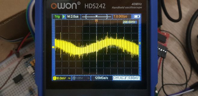
Handheld-Oszilloskop mit Sinuswelle auf Display
owon HDS242 40MHz Handheld oscilloscope Trig M:2.0us T:0.000ps 256.6kHz 1 10.0mV 2 1.00V 125MSa/s CH1:AC 5.60mV
in „Mein neues LieblingsnetzteiL? OWON SPM6103“ · Mikrocontroller und Digitale Elektronik · · Fotos
-
Datei
dram.asm
Datenbus ;Port_Adress=Adressbus ;Port_Steuer.2=/RAS ;Port_Steuer.3=/CAS ;Port_Steuer.4=/WE .include "m16def.inc" .def null = r0 ; Null=0 .def voll = r1 ; Voll=255 .def SREG2 = r2 ; SREG Sicherung .def Temp1 = r16 ; 1. Temp .def Temp2 = r17 ; 2. Temp .def Temp3 = r18 .def RAM_Data = r19 ; Datenregister
in „LPC2292 und DRAM“ · Mikrocontroller und Digitale Elektronik ·
-
Datei
test_bas.c
N = 1 To 10 for (N=1; N<=10; N++) { //Cs = 0 PORTB &= ~(1<<PB2); T = 0; //Do do { T = T + 1; //Waitus 100 _delay_us(100); //If T > Tt Then Goto Nosignal if (T > Tt) goto Nosignal; //Loop Until Sdo = 1 } while
in „Code von Bascom nach C“ · Mikrocontroller und Digitale Elektronik ·
-
PDF
Maxim_PWM_Simu.pdf
1210 10% Manufacturing 2mOhm Active Cap 15uF 100V X7S 2220 20% COUT1 2 CGA9P3X7S2A156M250KB TDK 2.1mOhm 1.86nH Active Cap Ceramic 4.7uF 10V X7R 10% CVCC 1 LMF212B7475KGHT Taiyo Yuden Pad SMD 0805 125°C Automotive T/R © 2022 Maxim
in „Spule mit 4 Anschlüssen“ · Analoge Elektronik und Schaltungstechnik ·
-
PDF
SKKT41-Semikron_International.pdf
. 300 / 600 mA V T = 25 °C; I = 200 A max. 1,95 V T vj T VT(TO) Tvj 125 °C 1 V rT Tvj 125 °C 4,5 m Features • Heat transfer through aluminium DD ;RD Tvj 125 °C; V RD=V RRM V DD= VDRM max. 153) mA oxide ceramic isolated
in „Prüfung Thyristor“ · Analoge Elektronik und Schaltungstechnik ·
-
PDF
Maxim_PWM_MAX15046-2.pdf
1210 10% Manufacturing 2mOhm Active Cap 15uF 100V X7S 2220 20% COUT1 2 CGA9P3X7S2A156M250KB TDK 2.1mOhm 1.86nH Active Cap Ceramic 4.7uF 10V X7R 10% CVCC 1 LMF212B7475KGHT Taiyo Yuden Pad SMD 0805 125°C Automotive T/R © 2022 Maxim
in „Beuteilauswahl für isolierten Wandler 12V-12V,“ · Analoge Elektronik und Schaltungstechnik ·
-
PDF
FIN41_FIN.pdf
. Schaltleistung AC15 (230 VAC) VA 600 400 750 1-Phasenmotorlast, AC3 - Betrieb (230 VACkW 0,5 0,3 0,5 Max. Schaltstrom DC1: 30/110/220V A 12/0,3/0,12 8/0,3/0,12 16/0,3/0,12 Min. Schaltlast mW (V/mA) 300 (5/5) 300 (5/5) 300 (5/5) Kontaktmaterial Standard
in „MC für Motoransteurung programmieren“ · Mikrocontroller und Digitale Elektronik ·
-
 Bild
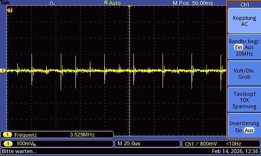
Oszilloskop-Messung eines Signals mit Impulsen
Tek Auto M Pos: 50.00ms Ch1 Kopplung AC Bandbr.begr. Ein Aus 20MHz Volt/Div. Grob Tastkopf 10X Spannung Invertierung Aus 1 Frequenz 3.529MHz M 25.0us Ch1 / 800mV <10Hz Bitte warten... Feb 14, 2026, 12:36
in „HP 53131A Messwert schwankt“ · Analoge Elektronik und Schaltungstechnik · · Oszi-Bilder
-
 Bild
Oszilloskop-Display mit zwei Messkurven
1 100mV/BW - 0.52div (500MS/s) M:20us 2 200mV/BW - -3.40div 96.0mv won S smart DS7102 100MHz 1GSa/s H1 H2 H3 H4 H5
in „Titel: CAN-Bus: ACK-Bit zeigt doppelte Differenz-Amplitude am Oszilloskop (Setup: Olimex ESP32 & Vic“ · Mikrocontroller und Digitale Elektronik · · Fotos

-
PDF
Infineon-IRLML2502-DataSheet-v01_01-EN.pdf
Voltage 100 1000 OPERATION IN THIS AREA LIMITED BY R ) DS(on) ( n )100 e ( u 10 t C TJ= 150 C e i u 10us r C 10 D i s r 100us e D e 1 , 1ms R I , TJ= 25 C 1 IS 10ms TA= 25 C TJ= 150 C VGS = 0 V Single Pulse 0.1 0.10.1 1 10 100 0.4 0.6 0.8 1.0 1.2 1.4 VSD ,Source-to-Drain Voltage (V) VDS , Drain-to-Source
in „Hilfe bei Bauteilidentifizierung erbeten (MOSFET, SOT23)“ · Offtopic ·
-
PDF
IRLML2502.pdf
Voltage 100 1000 OPERATION IN THIS AREA LIMITED BY R ) DS(on) ( n )100 e ( u 10 t C TJ= 150 C e i u 10us r C 10 D i s r 100us e D e 1 , 1ms R I , TJ= 25 C 1 IS 10ms TA= 25 C TJ= 150 C VGS = 0 V Single Pulse 0.1 0.10.1 1 10 100 0.4 0.6 0.8 1.0 1.2 1.4 VSD ,Source-to-Drain Voltage (V) VDS , Drain-to-Source
in „Umsetzung eines 5V Output mit ESP32 und AQY Halbleiterrelais“ · Mikrocontroller und Digitale Elektronik ·
-
 Bild
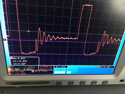
Oszilloskop-Messung eines Signals
y1:-9.60V y2:0.0mV 50.0mV- 0.00div Ma:23.60v Vk:0.759v F:118.2kHz 500MS/s Depth:10K M:1.0us Spannung CH1 CH2 won DS7102V
in „Spannungseinbruch nach Spule“ · Analoge Elektronik und Schaltungstechnik · · Fotos
-
 Bild
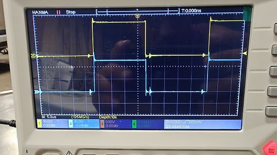
Abfotografiertes Oszilloskop mit Rechtecksignalen
HANMA Stop T:0.000ns M: 5.0us (125MS/s Depth:10k 1 10.0V 0.92div 2 10.0V -2.04div 3 1.00V 0.00div 4 50.0mV 0.00div CH1:DC- 800mV 23.4846KHz
in „bürstenmotor emv“ · HF, Funk und Felder · · Fotos
-
 Bild
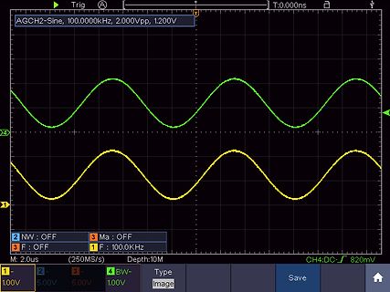
Oszilloskop-Screenshot mit zwei Sinuskurven
AGCH2-Sine, 100.0000kHz, 2.000Vpp, 1.200V T:0,000ns 4 1 2 NW : OFF 3 Ma : OFF 3 F : OFF 1 F : 100.0 kHz M: 2.0us (250MS/s) Depth:10M CH4:DC- 820mV
in „Massiever Überschwinger bei OP LT1213“ · Analoge Elektronik und Schaltungstechnik · · Oszi-Bilder
-
 Bild
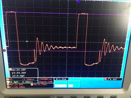
Oszilloskop-Messung eines Rechtecksignals mit Überschwingen
y:23.20V y1:23.20V y2:0.0mV 5V- -1.20div (500MS/s) Depth:10K 50.0mV 0.00div M:1.0us 8.40V Ma:23.60v Vk:8.759v CH2 F:118.2KHz
in „Spannungseinbruch nach Spule“ · Analoge Elektronik und Schaltungstechnik · · Fotos
-
PDF
Kompass_CMPS03.pdf
www.robotikhardware.de Englische Original-Doku CMPS03 - Robot Compass Module • Voltage - 5v only required • Current - 20mA Typ. • Resolution - 0.1 Degree • Accuracy - 3-4 degrees approx. after calibration • Output 1 - Timing Pulse 1mS to 37mS in 0.1mS increments • Output 2 - I2C Interface, 0-255 and 0-3599 • SCL speed up
in „uint8_t* konvertieren“ · Mikrocontroller und Digitale Elektronik ·
-
PDF
CrackManual_12-17-13.pdf
( )First, check the parts supplied in your kit against the check list on the preceding page. Call us at 360-697-1936, M-F 9-5 PT, if you are missing any components listed on the checklist. Power Entry and Power Switch ( )Now pick up a chassis plate and set it so that the round holes for the tube sockets
in „150V DC für Röhrenverstärker erzeugen“ · Analoge Elektronik und Schaltungstechnik ·
-
PDF
FT6236.pdf
Parameter Min Max Unit SCL frequency 10 400 KHz Bus free time between a STOP and START condition 4.7 \ us Hold time (repeated) START condition 4.0 \ us Data setup time 250 \ ns Setup time for a repeated START condition 4.7 \ us Setup Time for STOP condition 4.0 \ us 3 ELECTRICAL SPECIFICATIONS 3.1 Absolute
in „LilyGo T-Watch 2020 v1 Micropython“ · Mikrocontroller und Digitale Elektronik ·
-
PDF
eusi98lm.pdf
lettersforactual val- a a p a p Fig. 1 (solidline) illustratea typicalb ehavior ofthe ues (d ;a ;a ;f ;f ). a a p a p function (! ) ▯ ▯ =2 for the elliptihalfband ▯lter for The passband and stopband edge frequencies are func- n = 9, and f
in „Hilbert Transformation im uC berechnen“ · Digitale Signalverarbeitung / DSP / Machine Learning ·
-
 Bild
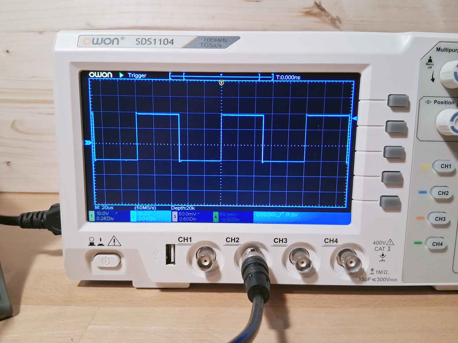
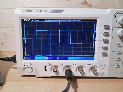
Owon SDS1104 Oszilloskop mit Rechtecksignal
owon SDS1104 100MHz 1GSa/s Trigger T:0.000ns M:20us (50MS/s) Depth:20k 10.0V 50.0mV 50.0mV 0.60Div 0.04Div 0.32Div CH1 CH2 CH3 CH4 400V CAT II 1MΩ 15pF ≤300VRMS
in „[V] Owon SDS1104, vier Kanal Oszilloskop, 100 MHz, 1GSa/s“ · Markt · · Fotos
-
Datei
avrdude.txt
V SCK period : 8.7 us Varef : 0.0 V Oscillator : 1.229 MHz avrdude: AVR device initialized and ready to accept instructions Reading | | 0% 0.00savrdude: stk500isp_read_byte(.., signature, 0x0, ...) avrdude: stk500isp_read_byte
in „Avrdoper(hid) Debian11 Avrdude“ · Mikrocontroller und Digitale Elektronik ·
-
PDF
Elektor.pdf
) au ui R15 25 dB 375 mV 0 Ω 30 dB 180 mV 11 kΩ 40 dB 180 mV 62 kΩ 50 dB 85 mV 173 kΩ 72 Elektor Electronics 2/2003 A U D IO +48V R7 R4 R2 R8 C7 C3 C8 8 8 C6 6 6 R12 R11 C1 R1 R5 R3 R10 C9 4 HZ1 C 3 a A1 A2 B1 B2 RÖ1 HZ2 1
in „Röhrenverstärkerstufe ECC XX welches System zuerst?“ · Analoge Elektronik und Schaltungstechnik ·
-
Datei
PeriphCode.c
; GPIOB_InitStructure.GPIO_Mode = GPIO_Mode_OUT; GPIOB_InitStructure.GPIO_Speed = GPIO_Speed_Level_1; //2MHz is enough for us GPIOB_InitStructure.GPIO_OType = GPIO_OType_PP; GPIOB_InitStructure.GPIO_PuPd = GPIO_PuPd_NOPULL; GPIO_Init(GPIOB, &GPIOB_InitStructure); GPIO_SetBits(GPIOB, GPIO_Pin_10 | GPIO_Pin
in „STM32F0 SWD LockOut“ · Mikrocontroller und Digitale Elektronik ·
-
PDF
popl02.pdf
function. Also, the memoization of the p kind done by lazy languages will not affect the correctness 1. ¾ mT ;sdom(¾ ) i dom(–)) + s ¾m;T s , of change-propagation, because the value remains the same whether it has been calculated or not. We therefore expect 2. there is a partial bijection B such that
in „DSP-CIM Forum Pool“ · Digitale Signalverarbeitung / DSP / Machine Learning ·
-
PDF
DE0_User_Manual.pdf
FL_ADDR[7] PIN_M4 FLASH Address[7] FL_ADDR[8] PIN_P2 FLASH Address[8] FL_ADDR[9] PIN_N2 FLASH Address[9] FL_ADDR[10] PIN_N1 FLASH Address[10] FL_ADDR[11] PIN_M3 FLASH Address[11] FL_ADDR[12] PIN_M2 FLASH Address[12] FL_ADDR[13] PIN_M1 FLASH Address[13] FL_ADDR[14] PIN_L7 FLASH Address[14] FL_ADDR[15] PIN_L6 FLASH Address[15] FL_ADDR[16] PIN_AA2 FLASH Address[16] FL_ADDR[17] PIN_M5 FLASH Address[17] FL_ADDR[18] PIN_M6 FLASH Address
in „FPGA Flash Speicher R/W - DE0 Board“ · FPGA, VHDL & Co. ·
-
PDF
LTSpice_XVII__Tutorial.pdf
Sternchen („Asterisk“) kennzeichnet eine Kommentarzeile. Und so würde z. B. das Ergebnis aussehen: * * [1] --- || * ) || .--- [3] * ) || ( * ) || ( * [2] --- || .--- [4] * .SUBCKT xformer_01 1 2 3 4 * ** Primary Lleak1 1 20 1mH Lpri1 20 21 1H Rpri1 21 2 1 Cpri1 1 2 20pF * **Secondary Lleak3 3 22 1mH Lsec1
in „Triac selbsterhaltend triggern“ · Analoge Elektronik und Schaltungstechnik ·
-
PDF
LTSpice_XVII__Tutorial_korr.pdf
Sternchen („Asterisk“) kennzeichnet eine Kommentarzeile. Und so würde z. B. das Ergebnis aussehen: * * [1] --- || * ) || .--- [3] * ) || ( * ) || ( * [2] --- || .--- [4] * .SUBCKT xformer_01 1 2 3 4 * ** Primary Lleak1 1 20 1mH Lpri1 20 21 1H Rpri1 21 2 1 Cpri1 1 2 20pF * **Secondary Lleak3 3 22 1mH Lsec1
in „Simulation LT Spice“ · Analoge Elektronik und Schaltungstechnik ·
-
PDF
FTDI_UM245R_Parallel_auf_USB.pdf
Parameter Description Min Typ Max Units Conditions Voh Output Voltage High 2.2 2.7 3.2 V I source = 1mA Vol Output Voltage Low 0.3 0.4 0.5 V I sink = 2mA Vin Input Switching Threshold 1.0 1.2 1.5 V ** VHys Input Switching Hysteresis 20 25 30 mV ** UM245R USB-Parallel FIFO Development Module Datasheet
in „FT245R sporalischer Initialisierungsfehler“ · Mikrocontroller und Digitale Elektronik ·
-
PDF
ATGmeo5c.pdf
230 (1.62) 3.3 0.84 2.8 1.13-1.79 Nm M22NXXA-LXX-XX-00 • 163 (1.15) 4.6 0.42 0.7 SIGMAX ® M22NXXB-LXX-XX-00 • 253 (1.79) 4.6 0.38 1.7 M22 Series M22NXXB-LXX-XX-00 • 253 (1.79) 2.3 1.52 6.8 2 rotor stack M22NXXB-LXX-XX-00 • 179 (1.26) 3.3 0.76 1.7 M22NXXC-LXX-XX-00 • 238 (1.68) 3.1 0.78 3.1 M22NXXC-LXX-XX-00 • 238 (1.68) 1.55 3.12 12.4 17 4.5 0.0036 2.5 (0.12) (0.025) (1.13) M22NXXC-LXX-XX-00 • 168 (1.19) 2.2 1.56 3.1 M22NXXD-LXX-XX
in „Schrittmotor-Treiber Stepper Motor Pacific Scientific Powermax II“ · Mikrocontroller und Digitale Elektronik ·
-
PDF
SP14N01L6ALCZ_Hitachi.pdf
STORAGE COMMENT MIN. MAX. MIN. MAX. Ambient Temperature -10℃ 60℃ -20℃ 70℃ (Note 2,3) Humidity (Note 1) (Note 1) without condensation 2 2 2.45m/s 11.76m/s Vibration - (0.25G) - (1.2G) (Note 4) (Note 5) 1h max. 2 2 29.4m/s 490.0m/s Shock - (3 G) - (50 G) XYZ directions (Note 5) Corrosive Gas Not Acceptable
in „[V] 1St. Hitach LCD SP14N01L6ALCZ 240x128 Pix mit CFL Converter“ · Markt ·
-
PDF
SSD1306-Revision_1.1__Charge_Pump__1_.pdf
1 1 3 6 6 M M M M G G M M M M C C . . C C O S . . . . . . . . . . . . S E C C . . C CO SSD1306Z BGGND V CCVCOMHIREFD[7:0] E (RD#) R/W#(W/R#) D/C# RES# CS# BSVDDS2VBATVBREF FR VSS C1N C1P C2N C2P C3 R1
in „5V an den Datenleitungen?“ · Mikrocontroller und Digitale Elektronik ·
-
PDF
SSD1306.pdf
1 1 3 6 6 M M M M G G M M M M C C . . C C O S . . . . . . . . . . . . S E C C . . C CO SSD1306Z BGGND V CCVCOMHIREFD[7:0] E (RD#) R/W#(W/R#) D/C# RES# CS# BSVDDS2VBATVBREF FR VSS C1N C1P C2N C2P C3 R1
in „OLED Grafik Anzeige“ · Mikrocontroller und Digitale Elektronik ·
-
PDF
5500-0080_VQC_DisplayAdapter_V2R1.pdf
SP2 74HC138N 3 Z4 LED DUTY CYCLE CTL SLAVE J2 AO3401A R5 SCKOUT MASTER Q5 1 SCK (OUT) R23 U6B 1 2 33R DOUT 2 MOSI (OUT) 9 A Q 12 DL- 3 DLATCH- 33R 5 C17 3 Z5 Z-STROBE B 10 Q GND 1n0 ZE- 4 Z-STROBE SLAVE B GND B AO3401A 5 ZE- GND Cext 6 C25 VCCZ Q6 6 tp=150us 11 7 1 2 RESET- 8 U6A CLR RX/CX 10n, C0G ZSTROBE 7 RESET- 4 1 74HC123D,653 1 C18 3 Z6 8 ZSTROBE OUT Q N A VCC 1n0 VCC 9 +5V 13 Q G AO3401A GND 10 GND GND 2 R27 1 2 VCCZ 14 B GND 2 100K 1 Q7 2 CON10 Cext C D2 C24 15 RX/CX V CLR 3 VCC J4 R26 3 100-1100us C19 DNP
in „Als Mikro noch Makro war: Die "Dicke Tal- Uhr"“ · HF, Funk und Felder ·
-
 Bild
Oszilloskop Messung digitaler Signale
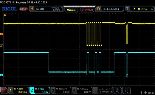
MSO5074 Fri February 07 18:43:12 2025 RIGOL STOP H 500us 10Ms/s 20Mpts Measure STOP/RUN D 303.3326ms T 1 2.46V A 1 2.00V +880mV 2 2.00V -5.68V 3 100mV 0.00V 4 100mV 0.00V L 0 1 2 3 4 5 6 7 8 9 10 11 12 13 14 15 GI GII 18:43
in „Was ist das für ein Protokoll?“ · Mikrocontroller und Digitale Elektronik · · Oszi-Bilder
-
 Bild
Oszilloskop Messung zweier Kanäle
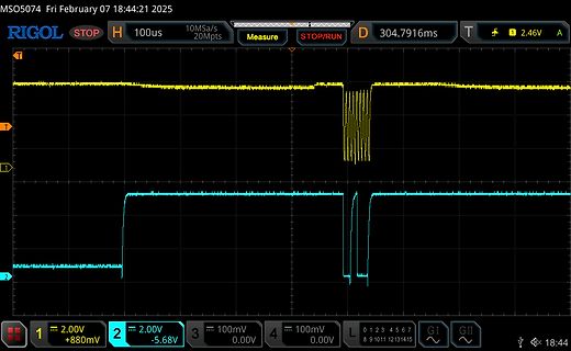
MSO5074 Fri February 07 18:44:21 2025 RIGOL STOP H 100us 10MSa/s 20Mpts Measure STOP/RUN D 304.7916ms T 1 2.46V A 1 2.00V +880mV 2 2.00V -5.68V 3 100mV 0.00V 4 100mV 0.00V L 0 1 2 3 4 5 6 7 8 9 10 11 12 13 14 15 GI GII 18:44
in „Was ist das für ein Protokoll?“ · Mikrocontroller und Digitale Elektronik · · Oszi-Bilder
-
Datei
fcounter.c
if(flag_it0==1){ TR0=1; TR1=1; } if(flag_it0==2){ TR0=0; TR1=0; } } IRQ_VECTOR(timer0int,TIMER0) void timer0int (void) interrupt { owerflow0++; } IRQ_VECTOR(timer1int,TIMER1) void timer1int (void) interrupt { owerflow1
in „frequenzcounter fast fertig“ · Mikrocontroller und Digitale Elektronik ·
-
PDF
JW5015B.pdf
VVIN<40V 776 800 824 mV Top Switch Resistance R DS(ON)T 130 mΩ Bottom Switch Resistance R DS(ON)B 70 mΩ VIN40V, VEN0V, Top Switch Leakage Current ILEAK_TOP 1 uA VSW=0V Bottom Switch Leakage ILEAK_BOT VIN V SW= 40V, VEN0V 1
in „Bezugsquelle für JW5015B ?“ · Analoge Elektronik und Schaltungstechnik ·
-
PDF
SDC7500_EN.pdf
Regulation Delta_VL Iref=1mA~10mA 1 15 mV Short-circuit Output Current Isc Vref=0V,Ta=25℃ 55 mA Output Voltage Change with ∆TA=MIN TO Delta_VT 0.2 1 % Temperature MAX PWM SECTION Input Threshold Voltage Vth DUTY=0 4 4.5 V Input
in „Wechselrichter defekt“ · Analoge Elektronik und Schaltungstechnik ·
-
PDF
SFH3010Z_.pdf
µs r f Rise and fall time IC= 1 mA, V CC= 5 V, RL = 1 kΩ Kollektrr-Emitter-Sättigungsspannung V CEsat 140 mV Collector-emitter saturation voltage I = 10µA C 2 Ee = 0.5 mW/cm , λ = 950 nm 2003-01-30 3 SFH 3010 Directional Characteristics
in „Problem ADC“ · Mikrocontroller und Digitale Elektronik ·
-
Datei
fcounter.c
== 0){ val_T1=h_byteT1*0x100+l_byteT1; } if(owerflow0 >= 1){ val_T0=h_byteT0*0x100+l_byteT0+(0x10000*owerflow0); } if(owerflow1 >= 1){ val_T1=h_byteT1*0x100+l_byteT1+(0x10000*owerflow1); } val_T0-=1; //ergebnis=val_T0
in „frequenzcounter fast fertig“ · Mikrocontroller und Digitale Elektronik ·
-
PDF
HITACHI-SP14Q002-A1_DM.pdf
Y80 D N M 1 D T I : Y1 3 4 ∗ X D X 0 1 0 1 0 X 8 8 1 1 2 X X X X X 5 6 7 I I I Y E L L W P F O U C ∗ P S E D F P 3 M A O C ~ R L P D S V E F F O F I V V V C C D D V V KAOHSIUNG HITACHI DATE MAR.18.’99. 7B64PS
in „SP14Q002-A1 aus eBay - Erfahrungsaustausch“ · Mikrocontroller und Digitale Elektronik ·
-
PDF
Verkauf-Elektronik-Werkstatt-mit-allem-Drum-und-Dran.pdf
V (DC + AC Spitze) oder 500 V Spitze-Spitze bis 1 kHz Horizontalteil Zeitablenkung: 0,1 us / Div … 2 s / Div in 1-2-5er Schritten (20 kalibrierte Stellungen) Genauigkeit Zeitablenkung: ± 3% (10 Grad bis 35 Grad) Wobbel-Funktionsgenerator Peak Tech 2830
-
PDF
SPI_Interface_On_GPS_Receiver_A2035_H.pdf
error codes (i.e. B4 A7 in hex character) will be appearing. NMEA formatɿ $GPGGA,000050.058,,,,,0,00,,,M,0.0,M,,0000*5E $GPGSA,A,1,,,,,,,,,,,,,,,*1E $GPGSV,3,1,12,01,00,000,,02,00,000,,03,00,000,,04,00,000,*7C $GPGSV,3,2,12,05,00,000,,06,00,000,,07,00,000,,08,00,000,*77 $GPGSV,3,3,12,09,00,000,,10,00,000,,11,00,000,,12,00,000,*71 $GPRMC,000050.058,V,,,,,,,191210,,,N*4F $GPGGA,000051.065,,,,,0,00,,,M,0.0,M,,0000*51 $GPGSA,A,1,,,,,,,,,,,,,,,*1E $GPRMC,000051.065,V,,,,,,,191210,,,N*40 Hexadecimal format ouputğ▯▯ 24 47 50 47 47 41 2C 30 30 30 30 35 30 2E 30 35 38 2C 2C 2C 2C 2C 30 2C 30 30 2C 2C 2C
in „Schlampiges GPS-Receiver Datenblatt (Maestro 2035-H)“ · Mikrocontroller und Digitale Elektronik ·