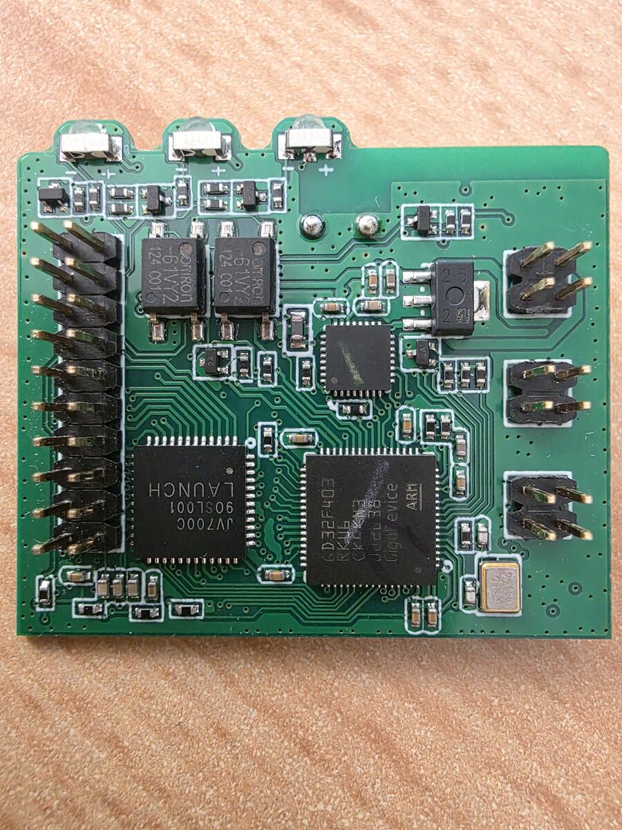
Hallo zusammen, ich möchte den Stromwandler QNCT16L 1000/1 nutzen um Strome in 230V Kreisen zu messen. Dazu habe ich parallel zum Stromwandler einen Burdenwiderstand von 360Ohm geschaltet. Das eine Ende vom Burden hängt am µC ADC Eingang und das
PC, auch indirekt über RS232 oder USB? Macht es einen Unterschied, ob du den Stromwandler auf der "L" oder "N"-Seite der Netzleitung hast, also Stecker mal umdrehen?
Wait, the real logic:* The cost of the trip vs the cost of the gas bought. * Cost to drive there: ~0.05L. Cost of gas to fill: 40L. * Ratio is 1:800. * So driving is economically fine. * But walking is better for the environment. * So, **Walk** is the socially and personally responsible answer (unless
e n t The input voltage to be measured is applied to a DC attenuator and a DC amplifier: D CR04M P L I 4aF E R Late —WA van tooo not BAS.Baw6z Bram 1ns ni3 z 1 CLIP dp e93 ¥05 07" pe “i Eebe F gae as ara?z73 5 4p§1 > ¥18g2 ~¥L HEFGON = aa ATENUAOR|* = ): 6 “ A? 4] jsn yet cr | r-hRID | COs VAe We tii
Automatic Multimeter PM2521 Service Manual | 7 .f /, , | SnfcnsaEimtvsn P H I L I P S Aut tc Multimet > i . Service Manual 9499 475 01911 8 2 0 4 0 7 E e e e e o e L L L L L L TE = e c y wae | S R e t e n e e e o e 1- f o e e \ -— Cees L e . cece — . s o | . .7”power . ¥-fema -O2A-t0a
inputs Ein enable input Eout enable output Gs group select output Op toOz outputs T R U T H T A B L E D O S S O D R n o o e o c e L y X ] xX] xp xp xp xp xP X i e L P e y e L H U L L L L e y e L L LP L y e yep u y H J H I X | ] xX} xX] x] x) x} xy] HP H P A ] AH L w f e f e l x | x } x } x f x d x f a y a f a d e f e w f e f t e p u } x} x] xp x f x f p a f a t e p a g e H E L L } L ] RY xX} xX} x] x X p P a u T a L L L a f e d t e f e p e t a } xf x } P x d a f e t a p a g e w f e f e p e f e c f e f af xt x f a t e d a t e y e H O L L L L L L HI X ] H Y I L LP H E a f e
Ausschlaggebend ist das Bild: 05_Schlaffzimmer_01.05.2026.jpg Dort sieht man, die möglicherweise nicht perfekte, Pegelung/ Verstärkung der gesamten Audio-Testumgebung. Das Mikrofon, AKG C 1000 S MKIV, der Fethead mit ca. +27 dB
Nyquist-Shannon-Abtasttheorem. Also, f_s = 192 Khz: f_{max} = 192 KHz /2 = 96 kHz = 96.000 Hz. Das sehen wir im Bild (05_Schlaffzimmer_01.05.2026.jpg).
Harry L. schrieb im Beitrag #8037413: > Wolf17 schrieb im Beitrag #8037407: >> Mich interessiert welche Abstimmspannung sich beim preiswerten (10€) >> 10MHz Frequenzstandard mit dem OCXO Modul von CTI OSC5A2B02
Harry L. schrieb im Beitrag #8037413: > ca. +1,8V Danke für den Messwert. Neue Werte kamen hier bisher leider nicht mehr, dafür wurde mein Thread für ein Nebenthema gekapert, das besser in einem eigenen Beitrag
Geht es um ICs oder das Display? Das LCD mit 75 Kontakten (davon 16 nc not connected) heißt: L.C.D. 5322 130 90158 532213090158 Quelle: 126-seitiges Service-Manual Seite 81 http://bee.mif.pg.gda.pl/ciasteczkowypotwor/Philips/pm2519.pdf Das Segment-Layout sieht man im Schaltplan auf Seite
n60,0 57,9 Xilinx (Mul+Add) FloPoCo PCS-FMA FCS-FMA y 36,9 0.54 0.74 2.67 2.36 n40,0 a20,0 21,6 14,2 L 0,0 The increased performance of our P/FCS-FMA units FloPoCo Xilinx PCS FMA FCS FMA Pipeline Mul+Add Unit Unit comes at a 4x to 5x increase in energy consumption. The XPower analysis details showed that
f_valid o-N-2 l op_last f_valid e-N-2 s E _ operand Control FIFO o-0 L-stage w+1-bit o FIFO c i op_rdy D_0 FIFO e-0 Shift Register 1 n (L words) a result o _ acc_result Control FIFO o-1 L-stage w+1-bit C f_wr_en A acc_rdy
0.8 mm ) % ( SUPPLY VOLTAGE: 1500 V T ANODE CURRENT: 1 µA U T MAGNETIC U 50 No.2 FLUX PMT O E O No.1 L MAGNETIC SHIELD CASE N A No. 0 L = 0 mm No. 1 L = 10 mm No.0 No. 2 L = 20 mm No. 3 L = 30 mm No. 4 L = 40 mm 0 2.5 5 Magnetic characteristics of photomultiplier tube used with magnetic shield case (PB
Fotodiode A o--|PB4 PB1|--o 470R -- LEDKette-Pin2 ; Fotodiode K o--|GND PB0|--o 470R -- LEDKette-Pin3 ; L_________/ ; ; ; ********************************** ; P O R T S A N D P I N S ; ********************************** ; ; (Add symbols for all ports and port pins with ".equ" here) ; (e.g. .equ pDirD = DDRB
(real or virtual via a capacitor) in order to eliminate the flickering. The value of the inductor L is a function of the input line frequency (50Hzor60 Hz), together with the characteristics of the lamp. The impedance of L is given by Equation 1: Z = L*ω L (1 with: ω = 2*π*F F = in Herz L = in Henry
integrated light source Mechanical Dimensions Remarks: Dimension of 5.0*5.4*1.57mm, default T.lerance of 0.05mm PIN Configuration PIN Function NO. Symbol PIN Function description 1 VDD POWER SUPPLY Power supply 2 DOUT DATAOUT Control data signal output 3 VSS GROUND Ground,data & power grounding 4 DIN DATAIN
WEERSTATION Bedienings- en veiligheidsinstructies STAZIONE METEOROLOGICA RADIOCONTROLLATA Istruzioni per l'uso e la sicurezza ESTACIÓN METEOROLÓGICA INALÁMBRICA Instrucciones de uso y seguESTAÇÃO METEOROLÓGICA SEM FIOS Instruções de funcionamento e de segurança IAN 500471_2504 Inbetriebnahme / Bedienung und
gerade da ist die Gefahr für Heizung etc. am größten. Imho kommst du mit einem Notstromaggregat und 20l Benzin deutlich günstiger wenn wirklich mal länger als 24h Stromausfall ist. Alles in allem war die Planung, Installation und Inbetriebnahme kein Hexenwerk wenn man da ein bisschen Ahnung und Hilfe
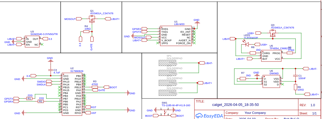
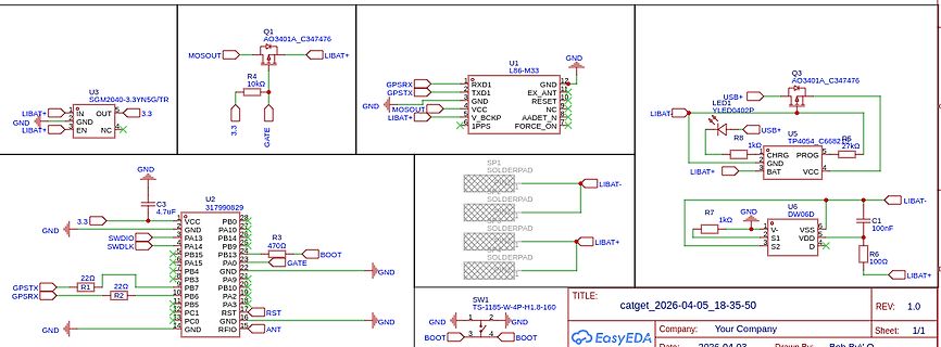
kurzfristig ab kann. Der im LOKO-Proj. kann max 2A. Wenn ich mir das PDF vom Hardware design anschaue vom L86-M33 steht dort das die höchste benötigte Stromaufnahme 100mA beträgt somit wäre ich doch absolut in der "Range" Jörg W. schrieb im Beitrag #8033602: > Die Physik lässt sich nicht überlisten: alles
Hallo an Alle, Ich habe letztens einen Rohde & Schwarz DMDC05 RDS Decoder bekommen. Dieser hat einen Eingang der mit MPX gekennzeichnet ist und hat eine Triax-Buchse. Mit Broadcasting Hardware hatte ich bisher noch nicht all zu viel zu tun. Habe mich daher im
(=2x19kHz) modulierten Stereodifferenzsignal besteht, mit dem sich zusammen mit dem Monomix wieder L und R herstellen lassen. Da es sich idR. um das unbearbeitete Signal vom FM Demodulator handelt, ist außerdem ARI+RDS mit 57kHz (=3x19kHz) darin enthalten. Das Signal ist bei analogen Monoempfängern
updated to new STK platform with USB-C . B06 2020-09-09 New revision to include BRD5001A Rev. A09. B05 2020-09-09 New revision to include BRD5001A Rev. A08. B04 2020-04-22 New revision to include BRD5001A Rev. A07. B03 2020-01-14 New revision to include BRD5001A Rev. A06. B02 2019-12-06 New revision to include BRD5001A Rev. A05. B01 2017-12-19 New revision to include BRD5001A Rev. A04. B00 2015-03-23 New revision to include BRD5001A Rev. A03. A02 2015-02-11 New revision to include BRD5001A Rev. A02. A01 2014-12-18 New revision
LED1 LED3 LED4 250 100n 2k2 D D TITLE: Sheet_2 REV: 1.0 Company: Your Company Sheet: 1/1 Date: 2019-05-15 Drawn By: g3gg0.de 1 2 3 4 5 1 2 3 4 5 T VCC ESP32 _ WS2812 P 2 1 U4 M L L ESP32-WROOM/WROVER T R R I E O D D R 1 2 A R7 N N N 2 1 A 1k O O O S 2 23 16 L L L W S 24O15 I153 W 25O2 G14 VCC5 IO0 26O0
in Farbe und bunt: https://www.amazon.co.uk/2-54mm-Connector-Socket-Crimps-Compatible/dp/B0BLZC9J6L
haben zwar 2,50 mm nominell als Pinabstand > (ohne Toleranz im Datenblatt), tolerieren allerdings 0,05 mm im > Boardlayout. Also 6-pol JST-XH passen problemlos in Lochraster (meine sind von Ali, evtl haben die schon 2,54 Raster)
, Leakage in Inhibit State vs. Figure 7. On−State Characteristics Temperature 3.2 ) 2.8 1.20 D Z L 1.15 A 2.4 NORMALIZED TO T A= 25_C R O 1.10 ( 2.0 D T E 1.05 E I R 1.6 A R M 1.00 C R G 1.2 N I H 0.95 D I O 0.8 V H 0.90 ,H I 0.4 0.85 0.0 0.80 −40 −20 0 20 40 60 80 100 −40 −20 0 20 40 60 80 100 TA
s e S i 0,8A K altgerätebuchse1 04 b r S i 0,8A K a ltg e rä te b u c h sEIN/AUS - S c h a lte r K l. 1 05 b r EIN/AUS - S c h a lte r K l. 2 L e itu n g s v e rb in d e r 2 -p o l. 06 b l K a ltg e r ä te b u c h s e E in/A us - S c h a lte r K l3 07 b l E in/A us - S c h a lte r K l4 L e itu n g s
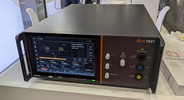
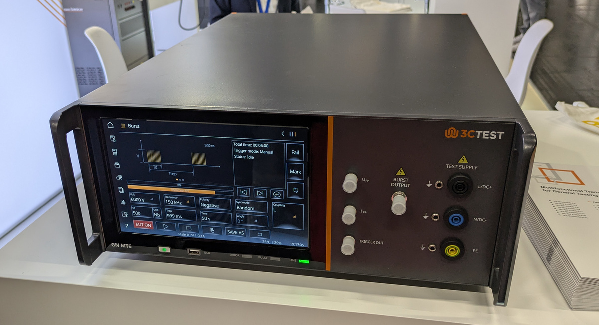
Burst Total time: 00:05:00 5/50 ms Trigger mode: Manual Status: Idle Fail Mark 6000 V 150 kHz Negative Random Coupling EUT ON SAVE AS 25°C | 29% 19:17:05 3CTEST TEST SUPPLY U_PP BURST OUTPUT L/DC+ I_PP N/DC- TRIGGER OUT PE
DUPLED NC 12 25 LINKLED 0 1 2 3 4 1 1 1 1 1 1 1 2 2 2 2 2 C D D D D G D P D O D D N G V G V V G C V V S L A A A A A T A 1 R P S Figure 1. W5500 Pin Layout 1.1 Pin Descriptions Table 1. Pin Type Notation Type Description I Input O Output I/O Input / Output A Analog PWR 3.3V power GND Ground W5500 Datasheet
Loop (PLL) Power Amplifier Control Logic TEST VBAT XT1 XT2 VDDA Power Management UHF Transmitter L e PAOUT TP1 SupplySwitch PowerOnReset A s L w m Test/Debug X O P P A VSSPA Logic TP2 SwitchLogic PortSenseLogic ControlLogic VSSA RISC Controller and Peripherals Watchdog Interrupt Timer System Timer
Thread dazu eröffnen. Danke. [1] https://eur-lex.europa.eu/legal-content/DE/TXT/HTML/?uri=OJ:L_202401689
Harry L. schrieb im Beitrag #8034746: > So....mir ist es endlich gelungen, meinen Strixx Halo in einem > LCX-Container zu nutzen, und im Anhang seht ihr das Transkript des 1. > Versuch mit ollama und einem
edge of E signal. Table 6-2: Control pins of 6800 interface Function E R/W# CS# D/C# Write command ↓ L L L Read status ↓ H L L Write data ↓ L L H Read data ↓ H L H Note (1↓ stands for falling edge of signal H stands for HIGH in signal L stands for LOW in signal In order to match the operating frequency
Isolationsgefräst hab ich noch nie. Meine Fräse ist etwas unhandlich: https://www.youtube.com/watch?v=YWUu4TmL8yo Nicht meine. Meine ist umgebaut auf LinuxCNC
Dietrich L. schrieb im Beitrag #8028385: > daher ist das Fehlen des > Milchaufschäumes für mich ein Vorteil, weil weniger kaputt gehen kann... Ähm... Nun muss ich doch mal nachhaken: 1. Wie geht ein Milchaufschäumer
edge of E signal. Table 6-2: Control pins of 6800 interface Function E R/W# CS# D/C# Write command ↓ L L L Read status ↓ H L L Write data ↓ L L H Read data ↓ H L H Note (1↓ stands for falling edge of signal H stands for HIGH in signal L stands for LOW in signal In order to match the operating frequency
brandnew. //No need to buy just reset it! //How it works: Every 5s, the chip is programmed, the led (L on Arduino UNO R3, LED_BUILTIN) blinks //if everything is ok (Memory copied AND checked). Serial connection is not compulsory it's only used for debug. //Successfully tested with Arduino Uno R3 // Sources
!) Hinweis in https://www.mikrocontroller.net/topic/583044#new https://media.elv.com/file/2001_05_09_leduhr.pdf Ein blindes Huhn findet auch mal ein Korn! :)
Klaus L. schrieb im Beitrag #8023051: > https://de.elv.com/p/elektronische-analogdigital-uhr-P204161 > sind dort der alte Journalbericht und das neue Layout gelistet. Beides > hier auch schon gepostet. >
2 V + + VEN (L) EN Threshold Falling l 0.4 1.0 V I + EN Pin Internal Pull-Down Current V = EN = 16V 0.7 µA EN IN_P Negative Regulator – LDO Output Voltage Range l –32 –1.2 V V – ADJ Reference Voltage I – = –1mA l –

 Bild
Bild
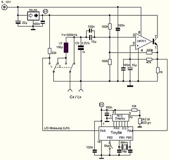
 Bild
Bild
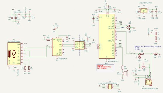
 Bild
Bild

 Bild
Bild
 Bild
Bild
 Bild
Bild