Bemessungswerte / Ratings: I - t Verhalten / I - t characteristics: N N BC_AC / 2 Art. No. I U N_AC / DC U d_max P d_max I t Bemessungs- Schmelzzeit N [V] [mV] [W] DC [A s] [A] strom-Faktor / 520.602 2) 32 mA 250 / 60 10.000 1,6 35 / 0,32 0,00008 / Melting time: 2) Rated current 520.603 40 mA 250 / 60 8.000 1,6
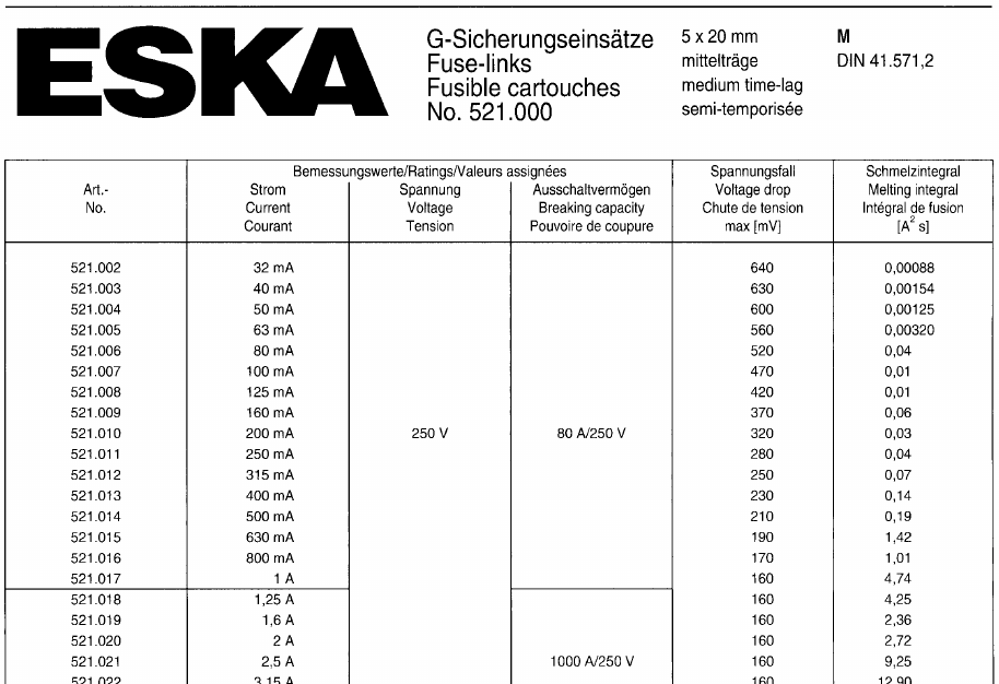
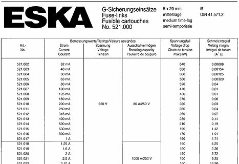
Ausschaltvermögen Breaking capacity Pouvoir de coupure Spannungsabfall Voltage drop Chute de tension max [mV] Schmelzintegral Melting integral ∫ fusion [A²s] 521.002 32 mA 640 0,00088 521.003 40 mA 630 0,00154 521.004 50 mA 600 0,00125 521.005 63 mA 560 0,00320 521.006 80 mA 520 0,04 521.007 100 mA 470
Max M. schrieb im Beitrag #7932943: > Welche Formeln sind für gewickelte Folienspulen anzuwenden? M.W. kann FEMM auch 2-dimensionale Magnetfelder in Polarkoordinaten brerechnen: https://www.femm.info
Max M. schrieb im Beitrag #7933003: > Wie kann ich bei FEMM eine Spule definieren aus Alufolie die gewickelt > ist? M.W. ist das für die Magnetfeldrechnung nicht relevant. FEMM will lediglich die
Bilateral Switches mit ca. 8V sind leider ausgestorben. NTE6407 (28V) NTE6408 (32V) NTE6411 (40V) NTE6412 (63V) DB4 (40V) SMP758 (15V) MKP3V240G (220V) selten. Eher findet man noch MKP SIDACs ab 70V von Littelfuse oder Breakover-Dioden wie IXBOD 1 für 600V-1200V unidirektional.
Haltestrom ist ca. U_be/R1 (bzw. U_be/R2 wenn R2<R1). Die maximale Sperrspannung entspricht U_ce_max und die Stromtragfähigkeit I_b_max der Transistoren. Eine externe Strombegrenzung ist sinnvoll. Wenn der höhere Leckstrom nicht stört, kann statt der Z-Diode ein Widerstand R3 verwendet werden. Die
RST APP Communication by WLAN for Commissioning Measurement Range Current range Direct connection: ≤ 63 A, external CT¹ : > 63 A Voltage range 1P (L-N): 85 ~ 299 Vac; 3P (L L): 148 ~520 Vac Energy accuracy ±1% Device Management Smart energy controllers up to 3 Smart chargers up to 2 Heat pump up to 1²
edgemore) after the reference clock edge arrives arrives at the pin? at the pin? CLOCK_TO_OUT ALLPORTS MAX 10ns CLOCK_TO_OUT ALLPORTS MAX 10ns MIN 2ns CLKPORT “clk”; MIN 2ns CLKPORT “clk”; TRACE uses different performance grades and conditions when doing Setup time vs. Hold time analysis. Table 2 has more
2. See electrical sofoperational considerations. 2. Derate linearly above T= 50°C at 2.17mW/OC. PD Max. (TA = 85°C) = 62mW. Electrical/Optical Characteristicsat =, 25OC .-.,,. - - 1/16 Duty Factor NOTES: 3. The luminous intensity ratio between segments within a digisdesigned so that each segment will
101N2100, 12-24V DC Fig. 2 Fig. 3 Battery protection settings Voltage (0.1 steps) Min. value Default Max. value ± 0.3V DC, Cut out V DC 9.6 10.4 17 12V all values Cut in diff. V DC 0.5 1.3 10 24V ± 0.3V DC, Cut out V DC 19 21.3 27 all values Cut in diff. V DC 0.5 1.3 10 Fig. 4 Wire Dimensions DC Size Max. length* Max. length* Cross AWG 12V operation 24V operation section [mm 2] [Gauge] [m] [ft.] [m] [ft.] 2.5 12 2.5 8 5 16 4 12 4 13 8 26 6 10 6 20 12 39 10 8 10 33 20 66 *Length between battery and electronic unit
Rated coil voltage code consumption voltage code consumption U U U R I at U U U * U ** R I at U N min max N N min max N V V V Ω mA V V V Ω mA 5 9.005 3.65 7.5 38 130 5 7.005 3.7 8.8 50 100 6 9.006 4.4 9 55 109 6 7.006 4.4 10.5 75 80 7 9.007 5.1 10.5 75 94 7 7.007 5.1 12.2 100 70 9 9.009 6.6 13.5 125 72
MAGNETOM Free.Max Breaking barriers siemens-healthineers.com/free-max Introduction Barriers limit the reach of MRI Today more than ever, access to healthcare should be a matter of course. But barriers still exist that
230V AC or 115V AC ± 10%, 50/60Hz Installation Category II Power Consumption: Single output: 250VA max; Triple output: 500VA max. Operating Range: +5ºC to +40ºC, 20% to 80% RH Storage Range: −40ºC to + 70ºC Environmental: Indoor use at altitudes up to 2000m, Pollution Degree 2. Cooling: Intelligent variable-speed
besseren Elkos, kannst stattdessen Folkos nutzen, die machen es sogar besser. Nimm mal z.B. je 3x22µ/63V-Folkos an Ein- und Ausgang, so holst du locker 1% mehr bei raus, einfach nur, indem du die, statt Elkos nimmst. Nächstes Mal nimmst du dann nur noch sowas, so wie ich, der sicher 15 Jahre keinen Elko
wenn man > nichts über die Spannungen und Ströme weiß, mit denen Du da arbeitest. 7,2-72V Akku, max. 100V Solarspannung, max. 25A an welchem Anschluss auch immer. Da keine Schottky im Spiel ist, sind die genauen Spannungen/Ströme ja eher unwichtig, man könnte den Strom auch verdoppeln, dafür die
Differential Probe60 Control and Power Module 60 Attenuator Adapters 61 Test Board 62 Service Policy 63 Troubleshooting 64 Probe Troubleshooting 64 Probe Control and Power Module Troubleshooting64 Removing and Replacing Assemblies 66 Differential Probe66 Probe Adapters 68 Probe Control and Power Module
I2C_HSM_EN=0 I2C_HSM_EN=1 (FastMode) (HighSpeedMode) TestConditions/ Parameter Symbol Comments Min Max Min Max Unit DCINPUTLEVELS InputVoltage LowLevel V 0.3×V 0.3×V V IL DDIO DDIO HighLevel VIH 0.7×VDDIO 0.7×V DDIO V HysteresisofSchmittTriggerV 0.05×V 0.1×V V HYS DDIO DDIO Inputs InputCurrent IL 0.1
Litze selbst Proximity- Effekt-Verluste erzeugt (vgl. [1,15]). 4Ir H =i 2⇡d 2( sin'~ ex+ cos'~ ey) (1.63) a Das innere H-Feld wird mit Hilfe der integralen Form des Durch- flutungsgesetzes (1.13) und der mittleren Stromdichte im Litzenleiter angegeben werden (Strom in z-Richtung). Das magnetische Gesamtfeld
Diagram The next parameter which must be calculated is the maximum allowable temperature rise, T (max):R T Rmax) = T (Jax)-T (Aax) (4) where • T (max) is the maximum allowable junction temperature (125°C) which is encountered in the application J • TA(max) is the maximum ambient temperature which is
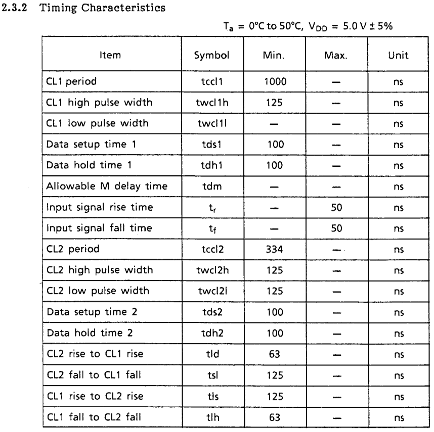
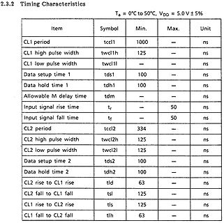
2.3.2 Timing Characteristics
Ta = 0°C to 50°C, VDD = 5.0 V ± 5%
Item Symbol Min. Max. Unit
CL1 period tccl1 1000 — ns
CL1 high pulse width twcl1h 125 — ns
CL1 low pulse width twcl1l — — ns
Data setup time 1 tds1 100 — ns
Data hold time 1 tdh1 100 — ns
Allowable M delay time tdm — —
Diode von Ausgang zu Eingang. Sind alle Kondensatoren wie im Datenblatt angegeben verbaut. Wird die max. Eingangsspannung eingehalten. ...
Stefan B. schrieb im Beitrag #7912486: > Der 7815 kann lt. DB bis 35V max., bei etwa 40V Eingangsspannung > schaltet er dann in der Steuerung ab. Glück gehabt, dass der nur "abschaltet". Wenn man die Absolute Maximum Ratings verletzt kann auch sowas passieren wie im https
us for more details. Item Characteristics Operating temperature range -55 ~ +105C Leakage current max. I = 0.01CV or A whichever is greater (after 2 minutes) Capacitance tolerance ±20% at 120Hz, 20C Dissipation factor max. WV 6.3 10 16 25 35 50 (at 120Hz, 2C) tanδ 0.27 0.23 0.19 0.15 0.13 0.11 WV 6.3
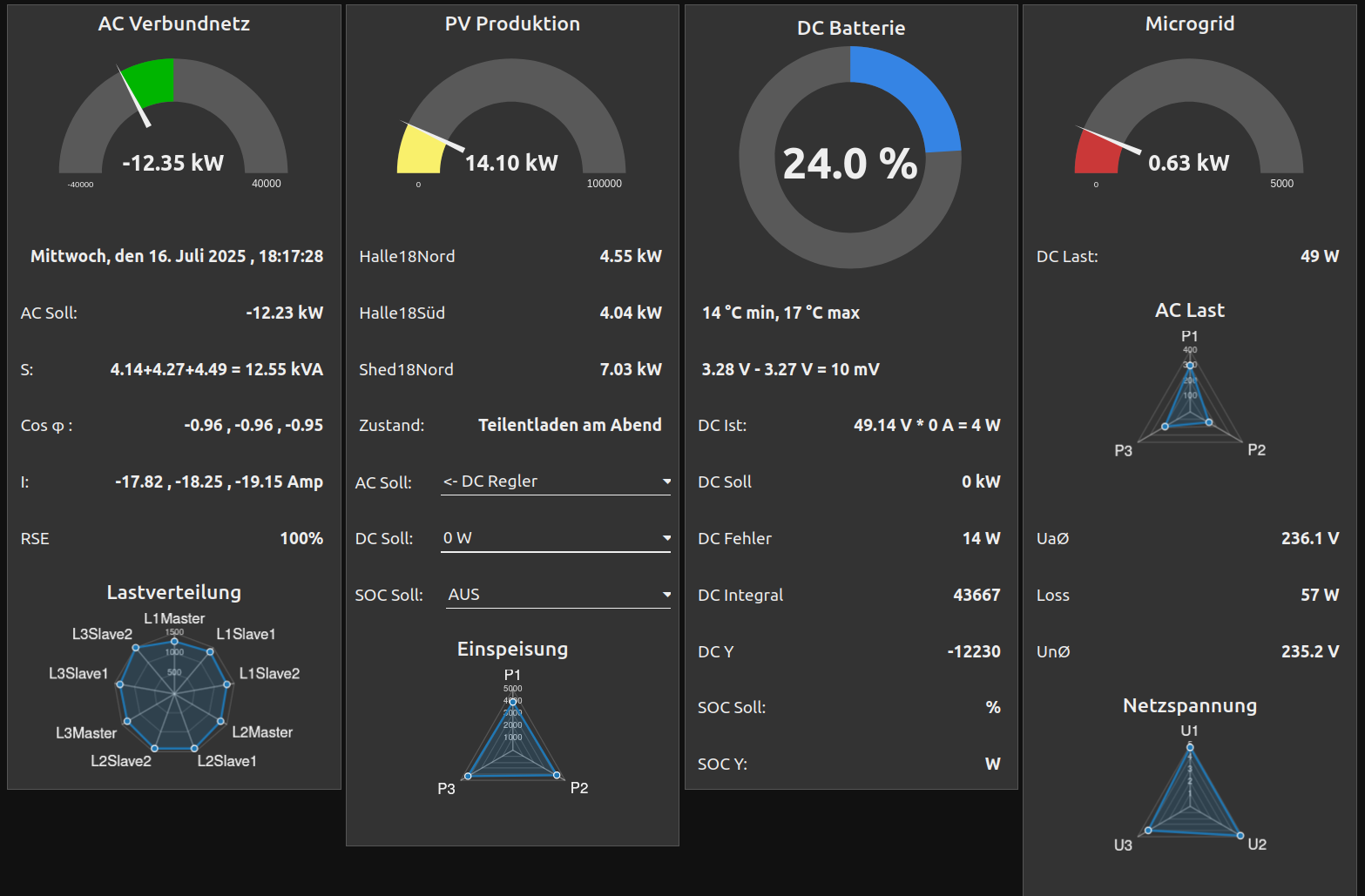
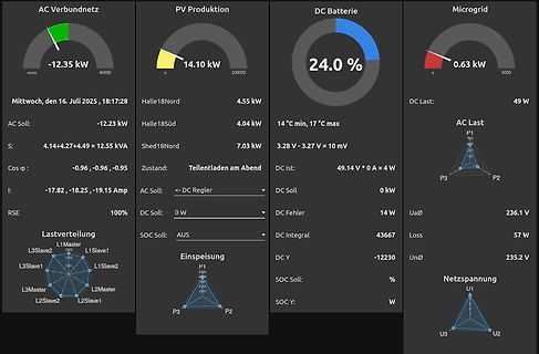
AC Verbundnetz -12.35 kW PV Produktion 14.10 kW DC Batterie 24.0 % Microgrid 0.63 kW Mittwoch, den 16. Juli 2025, 18:17:28 Halle18Nord 4.55 kW AC Soll: -12.23 kW Halle18Süd 4.04 kW AC Last: 49 W S: 4.14+4.27+4.49 = 12.55 kVA 14 °C min, 17 °C max DC Last: P1 P2 P3 Shed18Nord 7.03 kW
channel 6 N7 Close channel 7 N8 Close channel 8 N9 Close channel 9 N10 Close channel 10 N11 Step mode, max channel is 2 N13 Step mode, max channel is 4 N14 Step mode, max channel is 5 N15 Step mode, max channel is 6 N16 Step mode, max channel is 7 N17 Step mode, max channel is 8 N18 Step mode, max channel is 9 N19 Step mode, max channel is 10 N20 Open all - stop scanning or stepping if applicable Scanning (cont.) N21 Scan mode, max channel is 2 N22 Scan mode, max channel is 3 N23 Scan mode, max channel is 4 N24 Scan mode, max
mehr die angegebene/erforderliche Kapazität. Bei Austausch: Die Werte dürfen auch größer sein, z.B. 63V/1000µF. Sie sollten Low ESR Typen sein, und die Geometrie muss natürlich passen ;-) Edit: Und 105°C-Typen sollten es auch sein.
Also ich spreche hier von der Becherlänge. ;) Durchmesser ging bis zu max. 14mm
: 74h Size: 8 bits Table 3-213 Lock Count Bit Access Symbol Description [7:4] R/W locked_cnt_noisy_max These bits set the max value of the hlock sensor for noisy signals. 8 is added to this value. Default = 7 stands for 15. These bits set the max value of the hlock sensor for clean signals. 8 is [3:0] R/W locked_cnt_clean_max added to this value. Default = 4 stands for 12. 3.9.18 H Loop Max State Address Offset: 17h Access: Read/Write Default Value: CBh Size: 8 bits 83 电子专业技术主页: HTTP://WWW.LCDHOME.NET 资料收藏: 版权归原作者所有 谨供学习用
Arbeit haufenweise. Das was ich also suche, ist eine Anfängertaugliche Station, so im Rahmen bis Max. 100€, da ich mir dann gerne noch ein Bausatz zum lernen holen wollen würde. Viele Grüße Jakob
Er hat doch geschrieben er ist in Ausbildung und sein Budget sind max. € 100,- ist es so schwer?
chem Stromwert und Auslöse- Betreiben von Baugruppen durch geschultes n Charakteristik (MT 0.2 A, T 0,63 A) verwen- Personal verantwortlich zu überwachen. Sind alle Eingabe-Menüs durchlaufen fragt Folgen bei Netzausfall h det werden. - Betreiben Sie die Baugruppe nicht in einer der µC-Akku-Master nochmal
IRLZ44NPBF ELECTRONICS CO.,LTD N-Channel Enhancement Mode MOSFET Package Information TO-220 SYMBOL MIN NOM MAX MIN NOM MAX A 4.40 4.57 4.70 0.173 0.180 0.185 A1 1.27 1.30 1.33 0.050 0.051 0.052 A2 2.35 2.40 2.50 0.093 0.094 0.098 b 0.77 0.80 0.90 0.030 0.031 0.035 b2 1.17 1.27 1.36 0.046 0.050 0.054 c 0.48 0.50
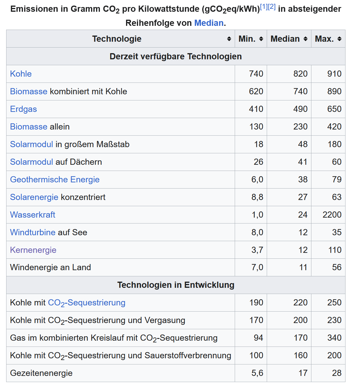
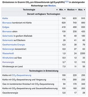
Emissionen in Gramm CO2 pro Kilowattstunde (gCO2eq/kWh)
Technologie Min. Median Max.
Derzeit verfügbare Technologien
Kohle 740 820 910
Biomasse kombiniert mit Kohle 620 740 890
Erdgas 410 490 650
Biomasse allein 130 230 420
Solarmodul in großem Maßstab 18 48 180
Solarmodul auf Dächern 26 41 60
Geothermische Energie 6,0 38 79
Solarenergie konzentriert 8,8 27 63
Wasserkraft 1,0 24 2200
Windturbine auf See 8,0 12 35
Kernenergie 3,7 12 110
Windenergie an Land 7,0 11 56
Technologien in Entwicklung
Kohle mit CO2-Sequestrierung 190 220 250
Kohle mit CO2-Sequestrierung
] D A l V M mm mm² km cm³ kg 0,053 0,0022 1298 2863 26 0,03 0,0007 416 294 2,63 0,02 0,0003 185 58 0,52 0,015 0,0002 104 18 0,16 0,01 0,0001 46 4 0,03 [/code] Also wäre das mit max. 0,02 mm Durchmesser realistisch machbar. Bei 0,01 mm Durchmesser sind
M mm mm² km cm³ kg 0,053 0,0022 1298 2863 26 0,03 0,0007 416 294 2,63 0,02 0,0003 185 58 0,52 0,015 0,0002 104 18 0,16 0,01 0,0001 46 4 0,03 [/code] Also wäre das mit max. 0,02 mm Durchmesser realistisch machbar. Bei 0,01 mm Durchmesser
via CCS connector in the vehicle thanks to easy OCPP integration and Autocharge functionality — — — MAX CHARGING POWER MAX CHARGING VOLTAGE DIMENSIONS Terra 24: 20 kW CCS 920 V DC Height 1900 mm / 74.8 in Terra 54: 50 kW CHAdeMO 500 V DC Width 565.5 mm / 22.3 in Terra 94: 90 kW Depth 880 mm / 34.6 in
Signals over recommended operating conditions (unless otherwise noted) STANDARD MODE FAST MODE UNIT MIN MAX MIN MAX SCL SCL clock frequency 0 100 0 400 kHz Hold time (repeated) START condition. After HD-STA 4 0.6 μs this period, the first clock pulse is generated. LOW LOW period of the SCL clock 4.7 1.3 μs
temperature Component: –40°C to +165°C. Tape and reel packaging: –40°C to +80°C Resistance to soldering heat Max three 40 second reflows at +260°C, parts cooled to room temperature between cycles Moisture Sensitivity Level (MSL) 1 (unlimited floor life at <30°C / 85% relative humidity) Recommended pick and place
direkt keine Sensoren oder gar Kameras installiert werden dürfen. Abstand der Personen zur Mauer ist max. 30cm. Die Mauer ist eine einfach gemauerte Steinwand in trockenem Innenraum. Für´s technische sollte das reichen.
Kay-Uwe R. schrieb im Beitrag #7895426: > Lernresistent? > Beitrag "60-63dBm Liearamp kompatibel mit Totalreflektion 0.1-30MHz > Kosten?" Du glaubst echt das mir so langweilig ist das ich hier jeden Thread auswendig kenne?
100kHz. Bei allem was man hier so gelesen hat, liegt der Fehler zu 99% in der Software. I2C ist mit max. 3mA bei LOW definiert, also min. 1,6k bei 5V. 2-4,7k sind OK.
Lu schrieb im Beitrag #7889694: > braucht leider viel > Strom Das muss ja kein 3poliger 63A-Schütz sein. Aber es sollte "Stromlos heißt definitiv Motor AUS" sein. Sonst macht es keinen Sinn. Z-Diode und Komparator funktionieren nur wenn der Akku zumindest noch etwas Strom hat. Gegen "Kabel
Nummern nicht im Kopf. (schnell rausgesucht) LTC1540 https://www.analog.com/en/products/ltc1540.html MAX931 https://www.mouser.de/datasheet/2/609/1/MAX931_MAX934-3471239.pdf Man kann auch was mit ner Z-Diode und einem Transistor was basteln. Da weiss ich jetzt aber nicht ganz genau, wie das da mit

 Bild
Bild
 Bild
Bild
 Bild
Bild
 Bild
Bild
 Bild
Bild
 Bild
Bild
 Bild
Bild