meinen Host µC jedes mal aufzuwecken. > Ein externes IC wird wohl weniger Strom verbrauchen, als ein SAM4E16E im > Sleep? Wer sagt das? Dieses kurze Aufwachen dauert wenige us und ist das Normalste in der Mikrocontrollerwelt. Siehe [[Sleep Mode]]. Dein SAM4E ist keine Linuxkiste.
: > > - Sleep Mode mit dem SAM4E > - RTC mit Millisekunden, wie die z.B. https://ww1.microchip.com/downloads/aemDocuments/documents/OTH/ProductDocuments/DataSheets/Atmel-11157-32-bit-Cortex-M4-Microcontroller-SAM4E16-SAM4E8_Datasheet.pdf
den Vorteilen ethernetbasierter Kameras im Computer Vision-Bereich. Der indische Kamera-Spezialist e-con Systems bietet unter der URL https://www.youtube.com/watch?v=3uUc33UIINI ein Lehrvideo an, das die Vorteile der Nutzung von Ethernet im Bereich der Computer Vision en Detail durchspielt.  trotzdem noch 10mV Fehler und teilweise nur einen eingeschränkten Nutzungsbereich (z.B. C3 bis 2,5V). Also 3,6 Bit Fehler best case. Also keine 12 Bit ADC sondern 8,4 Bit. Temperatur und weitere Faktoren noch garnicht berücksichtigt. Entweder ich übersehe was oder das Ding ist nach wie
; do0 : OUT std_logic; do1 : OUT std_logic; do2 : OUT std_logic; do3 : OUT std_logic); END COMPONENT; attribute syn_tpd1 of rcf16x4z : component is "ado,ad1,ad2,ad3 -> do0,do1,do2,do3 = 1.1"; attribute syn_tsu1 of rcf16x4z : component is "ado,ad1,ad2,ad3 -> ck = 0.5"; attribute syn_tsu2 of rcf16x4z : component is "wre -> ck = 0.5"; If you use Verilog: module SPR16X4A (DI0, DI1, DI2, DI3, AD0, AD1, AD2, AD3, WRE, CK,DO0, DO1, DO2, DO3) /* synthesis black_box syn_tpd1="AD0,AD1,AD2,AD3- >DO0,DO1
Conditions When TA Exceeds50°C. IPEAK-PEAK SEGMENT CURRENT - mA VF- PEAK FORWARD VOLTAGE - V Figure 3. Relative Luminous Efficiency Figure4. Peak Forward Segment (Luminous Intensity PerUnit Current) Current vs. Peak Forward Voltage. vs. Peak Segment Current. A3 A2 A i Ao - 1 2 3 4 5 6 7 8 9 A B C D E F ]A5 A4 0 0 0 1 1 0 I I I - * 0 % & ' 0 X t , / 1 1 Figure5. Typical 64 Character ASCII Set. Additional Character Font W3W.HPARCHIVE.COM - PackageDimensions (NOTE 31 [NOTE3) 381+ .25 3.8? 2 5 (100)T Y P ~ (.15+ 01) 1.15i ,011 NOTES MagnifiedCharacter
falsch verstanden Offenbar. Der Eingang ist nicht R2R Common Mode Input Range VCMR VSS–0.3 bis VDD–1.2 V Geht der Eingang über 5V-1.2V=3.8V darf der Ausgang machen was er will.
Danke euch, hab mein Verständnisproblem erkennen können :) Soul E. schrieb im Beitrag #7929873: > Verschalte die Dinger mal für Verstärkung x2 und lass den Eingang von > 1/4 Vdd bis 3/4 Vdd laufen. Damit sollte es linear bleiben. Das tut es, danke.
Resistance vs. Temperature 3.0 2.2 0.5 sq. in. Additional PCB Cu 2.0 2.5 ) ) ( 1.8 ( c 1.6 e 2.0 a P s 1.4 x 1.5 s 1.2 M R t 1.0 d 1.0 T z 0.8 a 0.6 0.5 m o 0.4 0.0 N 20 40 60 80 100 120 140 0.2 Junction Temperature (°C) 0.0 -75
Sheet ADA4807-1/ADA4807-2/ADA4807-4 300 10 25 V S ±5V ) 10 UNITS V 9 OIL BATH TEMPERATURE 24 µ ( (200 E 8 23 G G A T 7 22 L O 6 21 ) O100 V C V T 5 20 ( E S E S F 4 19 U F 0 O 3 18 T O T R D U 2 17 E R N M –100 I 1 16 E F I 0 15 T E G R I –1 14 U200 N P A –2 13 I H V = ±2.5V C –3 8 UNITS, SOLDERED TO PCB
clearing the grayfilter mask in cases where no black pixel is found in the mask. (default: 0.5) -p x, y; --mask-scan-point x, y Manually set starting point for mask-detection. Multiple --mask-scan-point options may be specified to detect multiple masks. -m x1, y1, x2, y2; --mask x1, y1, x2, y2 Manually
images, faster + 7 a a 4 Powered by Conventional Deep Resolve Gain & Sharp artificial intelligence 0.9 x 0.9 x 4.0 mm³ 0.5 x 0.5 x 4.0 mm³ TA 5:16 min TA 3:48 min 8 Magnetic Resonance · MAGNETOM Free.Max Image courtesy of University Hospital Erlangen, Germany High-V MRI – Value beyond barriers Breaking
Technology Corporation www.leadtrend.com.tw LD7536R-DS-01a December 2011 LD7536R Pin Configuration DIP-8 (TOP VIEW) SOT-26 (TOP VIEW) P D M P G C N O OUT VCC CS 8 7 6 5 6 5 4 YWP 36R TOP MARK 1 2pp 3 YYWWPP 1 2 3 4 GND COMP OTP U C C C O V N YY, Y : Year code (D: 2004, E: 2005…..) WW, W : Week code PP :
high-speed mode, and the internal circuits of the controller for high-speed mode are enabled. Figure 5-3 shows a detailed figure on how the I C high-speed mode is enabled followed by communication with data. Normal or Fast mode High-speed mode 8-bit controller code 0 0 0 0 1 X X X S Hs controlleA Target
do not use pointed objects to actuate the keys. The keypad is designed for finger operation only. 3 2091702_H - BK150FUE-1 Installation and User's Manual 2 Technical Data For BK150FUE-1 Smart Start™ NXT Boxes Dimensions of Housing (W x H x D) 11-13/16" x 19-11/16" x 7-7/8" (300 x 500 x 200mm) without
Power Dissipation vs. Figure 12. Common Emitter Characteristics Ambient Temperature oC V 22.4 1 1.3 = VCE = 10 V =E IC= 10 mA T C = 10 mA hre VC.25 TA = 25 C hfe T 2 h ie T 1.2 A A E hfe E1.15 U1.6 U 1.1 hie A A V1.2 hoe V1.05 T T 1 E E I0.8 I0.95 h re A A 0.9 L L R0.4 R0.85 h . R 0.8 oe A A H 0 C0.750
on parts mounting density. ordered with VDE option – See Ordering Information Table) Features 4. X = One−Digit Year Code, e.g. ‘3’ 5. YY = Two Digit Work Week Ranging • High Speed − 1 MBit/s from ‘01’ to ‘53’ • 15 kV/ s Minimum Commone Mode Transient Immunity at 6. S = Assembly Package Code V CM =
- NO LEAD (2.2) 8X (0.5) SYMM 1 8X (0.3) 8 SYMM 9 (3) 6X (0.8) (1.25) 4 5 (R0.05) TYP ( 0.2) VIA TYP (0.85) (3.3) LAND PATTERN EXAMPLE EXPOSED METAL SHOWN SCALE:15X 0.07 MAX 0.07 MIN ALL AROUND ALL AROUND EXPOSED EXPOSED
P. O. schrieb im Beitrag #7912087: > Ich habe gebrauchte 3,3V Varianten @25MHz (und einem 8-Bit ROM) Woran sieht man einem 68360 eigentlich die 3,3 V Variante an? Ich habe nur das Motorola Manual, und die Suchmaschinen geben sich zugeknöpft bei dem Thema
Cartman E. schrieb im Beitrag #7913722: > Woran sieht man einem 68360 eigentlich die 3,3 V Variante an? Am "L" bei MC68360RC25L. Es gibt bei NXP dazu eine Textdatei: [code] ISSUE DATE: 23-Mar-1998 NOTIFICATION
, since cl ch boost were employed. The Dynamic Controller was configured as a the exciters are the same as in the MAP3, the Dynamic Controller compressor and a limiter to limit the amount of added distortion was configured with the same set of parameters. After applying and low frequency level up to the
A is the same as the delay of the reverse signal from input A to output B in the above table. 3. x represents 1 or 2. Typical application circuit diagram 4 2V-8.6V VDD1 13 8 OUTB1 VDD2 C3 M1 1.8V-5V 1 100uF-470uF
SST39LF010/SST39LF020/SST39LF040/ SST39VF010/SST39VF020/SST39VF040 1-Mbit/2-Mbit/4-Mbit (x8) Multi-Purpose Flash Features Product Description • Organized as 128K x 8/256K x 8/512K x 8 The SST39LF010/020/040 and SST39VF010/020/040 • Single Voltage Read and Write Operations: devices are 128K x8, 256K x8 and 5,124K x8 CMOS - 3.0V-3.6V for SST39LF010/020/040 Multi-Purpose Flash (MPF) manufactured with Microchip’s proprietary, high-performance CMOS - 2.7V-3.6V for SST39VF010/020/040 ® • Superior
(@Ta=25C) Including Voltage Drop by Limiting Resistor (Right chart is enlarged chart.) Fig. 3 Temperature of OTutput Characteristics 4.0 max 3.8 typ 3.6 min 3.4 3.2 3.14V ] 3.02V t3.0 u 2.89V t2.8 O T V2.6 2.4 2.2 2.0 1.8 1.6 60 70 80 90 100 110 120 130 LVIC temperature[℃] Publication Date :
Komfortfunktionen für den Mehrschirmbetrieb mitbringt. Andererseits gilt, dass Updates - Stichwort Wayland versus X11 - insbesondere auf Systemen mit AMD-GPU zu überraschenden Abstürzen, beispielsweise bei der Aktivierung des Standby-Modus, führen. ### CircuitPython 10.0.0-alpha.8 verfügbar Im Hause Adafruit
veröffentlicht: [c] • ESWIN Computing EIC7700X SoC • RISC-V 4-core processors with frequency up to 1.8GHz • Self-developed NPU with AI computing power up to 20TOPS • On-board 64-bit LPDDR5 @ 6400Mbps [/c] Die verbauten Kerne
ist, nicht so einfach in ein eigenes PCB zu integrieren ist (layouttechnisch), aber sowas wie Wio-E5, STM32WL5MOC, Wio-E5 etc. aber schon. Gleiches gilt für den nackten SX126x Chip vs. fertige Module wie Wio-SX1262. Rahul D. schrieb im Beitrag #7909152: > Es wäre schön, wenn mir jemand das schreiben
Raspberry Pi - Arduino framework for RaspberryPI Heltec CubeCell - ASR650X series (CubeCell-Board, CubeCell-Capsule, CubeCell-Module etc.) PJRC Teensy - Teensy 2.x, 3.x and 4.x boards Silicon Labs EFR32 - Silicon Labs xG24, xG27 and other boards
a b c d e g h k m n o X 1 1 6 sserddA T yra irP B 6 7 8 9 0 1 2 3 4 5 6 7 8 9 0 N ( 1 1 1 1 2 2 2 2 2 2 2 2 2 2 3 U 5 ) ( P Q R S T U V W X Y Z [ \ ] ∩ ⎯ S P ) X 0 1 1 5 L R U G sserddA T D R ( yra irP ) 0 1 2 3 4 5 6 7 8 9 0 1 2 3 4 5 A G ( 1 1 1 1 1 1 4 ) ( @ A B C D E F G H I J K L M N O X 0 1 1 4 sserddA 6 7 8 9 0 1 2 3 4 5 6 7 8 9 0 L yra irP B 1 1 1 1 2 2 2 2 2 2 2 2 2 2 3 U 3 A 0 1 2 3 4 5 6 7 8 9 : ;
16 LED14 PCA9532BS LED3 4 15 LED13 LED4 5 14 LED12 LED5 6 13 LED11 7 8 9 1 1 1 6 7 S 8 9 1 E DE V E DE D 002aae520 L L L L L Transparent top view Fig 4. Pin configuration for HVQFN24 PCA9532 All information provided in this
VDD 18 8 Vp Vo 1 6 +5V 3 C 3 C 3 C 7 Vcc WR RD E ME IOE 15 2 3 2 7 12 BRQ A1 >> A1 /RTCCS >> CSO ALE F Vs U1 NC R72 40106 R52 7 GND F F F 52 16 8 17 5 2 1 F 5 3 U20 11 PUMP COUNTS VOL CNT P 6 P 4 P 2 51 NC A2
Hans H. schrieb im Beitrag #7906972: > Nach 3 Stunden Lauf unter Nennlast (Abluftschlauch in einem > abgedichtetem Flügelfenster) hat er den Versuch abgebrochen, weil in > Gerätenähe bei 1,8°C Abkühlung Schluss war. Das Rätsel kann ich nach
Dieter D. schrieb im Beitrag #7907001: > Hans H. schrieb: >> Nach 3 Stunden Lauf unter Nennlast (Abluftschlauch in einem >> abgedichtetem Flügelfenster) hat er den Versuch abgebrochen, weil in >> Gerätenähe bei 1,8°C Abkühlung Schluss war. > > Der Tester hat eine
BC546B, BC547A, B, C, BC548B, C BC547/BC548 2.0 1.0 I VCE= 10 V 0.9 TA= 25°C A 1.5 T = 25°C T A 0.8 E ) VBE(sat) IC B = 10 R 1.0 T 0.7 U O C 0.8 ( 0.6 VBE(on) V CE = 10 V D E D 0.6 A 0.5 I L 0.4 A V M 0.4 V 0.3 O , 0.3 0.2 F VCE(sat) IC B = 10 h 0.1 0.2 0 0.2 0.5 1.0 2.0 5.0 10 20 50 100 200 0.1 0.2
1.E-08 e 0.01 e T J 25 °C T J 60 °C R 1.E-09 T J 25 °C 0.001 1.E-10 0.0 0.2 0.4 0.6 0.8 1.0 1.2 0 5 10 15 20 Forward Voltage Drop, V (V)F Reverse Voltage, V (R) Figure 3. Typical Characteristics: IFvs. V F Figure 4. Typical Characteristics: I Rs. V R 100 10 ) A (Z , 1 n r u C r 0.1 v e R 0.01 t = 200 μs 0.001 20 22 24 26 28 Breakdown Voltage, V (V)Z Figure 5. Typical Characteristics: I vs. V Z Z SG-17VLZ-DSE Rev.1.2 SANKEN ELECTRIC CO., LTD. 3 May 26, 2025 https://www.sanken-ele.co.jp
MAX CHARGING POWER MAX CHARGING VOLTAGE DIMENSIONS Terra 24: 20 kW CCS 920 V DC Height 1900 mm / 74.8 in Terra 54: 50 kW CHAdeMO 500 V DC Width 565.5 mm / 22.3 in Terra 94: 90 kW Depth 880 mm / 34.6 in Terra 124: 120 kW (and 2 x 60 kW) Weight 395 kg / 871 lbs Terra 184: 180 kW (and 2 x 90 kW) (Terra
eine Variante, die neben einem Funkinterface auch PoE und Ethernet unterstützt. Spezifischerweise kombiniert die neueste Variante des Xiao-Ökosystems einen WizNet W5500 und einen ESP32-S3. 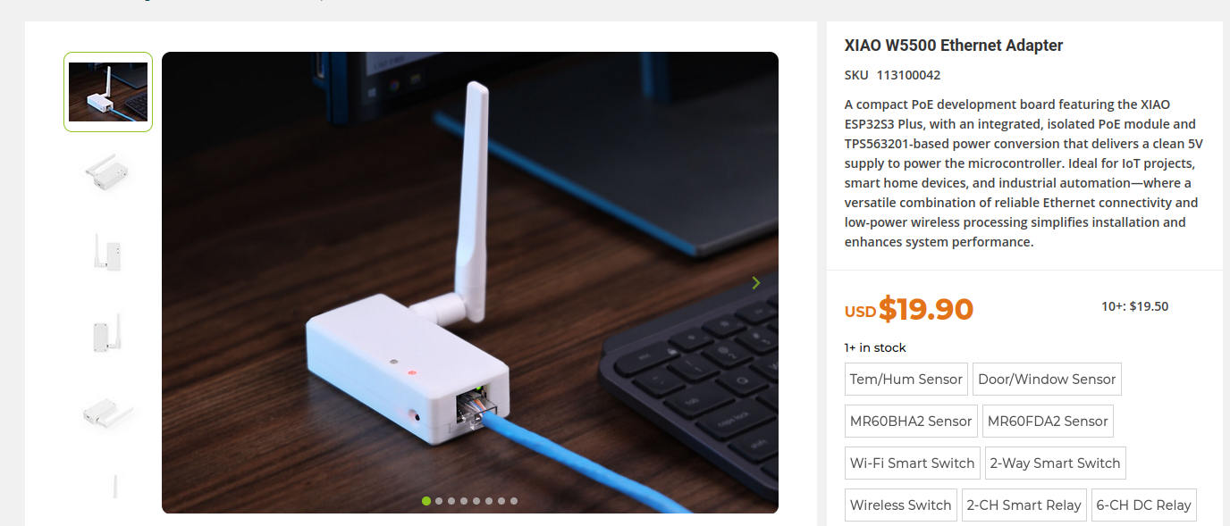 Bildquelle. https://www.seeedstudio.com
die neue Lütte rund 20 US-Dollar - die Bildquelle dient als Einsprungpunkt in den Onlineshop. ### e-Flesh – 3D-druckbare Berührungssensoren Berührungserkennung ist ein traditionell haariges Thema. Mit e-Flesh schickt ein Forscherteam ein neuartiges Verfahren ins Rennen, dass Magnetismus und 3-D-gedruckte
PINE2 PINE1 PINE0 Access R/W R/W R/W R/W R/W R/W R/W Reset x x x x x x x Bits 0, 1, 2, 3 – PINEn: Port E Input Pins Address [n = 3:0] Writing to the pin register provides toggle functionality for I/O. Bits 0, 1, 2, 3, 4, 5, 6 – PINEn: Port E Input Pins Address
Enable STB Data Latch CE# Output Enable OE# Logic Y-Decoder Y-Gating STB V Detector Timer t CC a L e X-Decoder Cell Matrix d A0–A18 d A 4 Am29F040B 21445E8 November 11, 2009 D A T A S H E E T CONNECTION DIAGRAMS 2 5 6 8 C E 7 A A A A V W A 1 4 3 2 1 32 31 30 A7 5 29 A14 A6 6 28 A13 A5 7 27 A8 A4 8 26
resulting in a slightly positive iJ4,σ) rev,D4) 1 iD,σt) =J5,σ) =S,σ(t) gate voltage of JFET J . T2e same is true in analog manner rev,D3) for the upper series connected JFETs. iJ3,σ) iJ5,σ) >J4,σ) >J3,σ) >J2,σ) >J1,σ) i (t) For turning the cascaded switch off, first the MOSFET is iJ2,σ) rev,D2 irev,
LiPo-Akku reicht. https://www.amazon.de/SW-Bluetooth-Radio-LED-Beleuchtung-wiederaufladbare-Unterst%C3%BCtzung-USB-MP3-Player-Blau/dp/B0DM1W8VYV?source=ps-sl-shoppingads-lpcontext&ref_=fplfs&smid=AKO0FL019F2AL&th=1 Jörg W. schrieb im Beitrag #7891045: > Was glaubst du, warum man hier wohl den Sendemast
bis jetzt noch nicht. Es gibt Bursts die etwa 80 Hz breit sind, aber auch 23.5 bzw 25 Hz . Anbei 2x Audio von Audacity mit der Modulation SAM und AM. Und ja es stimmt, es gibt hier einen Landwirtschaftlichen Reparaturbetrieb etwa 50 m entfernt. Da stehen die modernsten Fahrzeuge. Auf 433 MHz kommt
Sinnvolles rauslesen kann ich jetzt direkt trotzdem nicht: [code] aaaaaaaaaa 2dd4 5c323793bc8000f73d001e425fa4aeefc140687357908f0e302ec2e856cc74000007b8aa27e8a158051d57b7a46fd002a800001750000000281a05c1b02626078739b3f2c71111 aaaaaaaaaa 2dd4 ac210082bc81000000000000000000000000000000000000000000000000000000000000000000000000000000000000000000000000000000000000000003b3a60e031a98489eb5b69a6ecc532e24e544001001

 Bild
Bild
 Bild
Bild